1
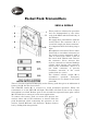
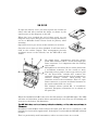
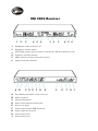
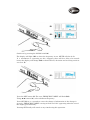
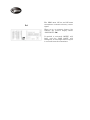
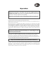
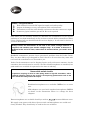
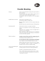
The Gradav Guide to
Sennheiser 3000 series
Radio Mics
Intro & Overview
The 3000 series of Radio Mic equipment is used in West End Theatre
productions, by Broadcasters, and those users looking for that extra quality
that is inherent in Sennheiser’s more expensive systems.
The EM 3032 dual receivers allow the user to
the system. Output
level adjustment, squelch control and a comprehensive LCD display are
there for the experienced user. A headphone socket per channel is a handy
facility for all users.
Metal casings are used throughout the range giving an improved RF
performance, and a greater robustness.
Where transmitter size is important we have the SK5012, which is much
smaller than the SK50/SK3063 pocket packs. There is a small cost for the
reduction in size, and the SK5012 does not indicate battery life on the
receiver as do all the other transmitters.
This guide has been written to assist the user who is new to this system to
get the result they are looking for with the minimum of time and worry. It
will also aid the experienced user whose memory needs a little help!
Fault finding is never easy, especially when you are under pressure. We
have added a section that may just save your reputation (and sanity)!
Pocket Pack Transmitters
SK50 & SK3063
7
6
5
1
2
4
3
8
These packs are identical in operation
and are distinguished by the silver
body of the SK50 and the black body of
the SK3063.
We supply these transmitters with the
aerials fitted. The connector (1) is a
screw-lock single pin Lemo connector.
It is important that the locking ring is
tight.
Microphones to fit socket (7) are either
fitted with a screwdown connector (as
the aerial) or more frequently with a
push to insert type; where a pull on
the barrel both unlocks and removes
the connector. Never unscrew this
style of connector as internal damage
results, often leaving the connector
stuck in the transmitter. This is a 3
pin Lemo connector, to prevent
accidental insertion in the aerial
socket (and vice versa).
The channel selector switch (2) is
screwdriver
operated.
Frequency
allocations are as shown on the front
panel (8).
There is a multi-segment LED display on the battery pack that gives an indication of
battery life (3). See the chart above.
The ON/OFF switch (4) is recessed to avoid accidental operation. When the
transmitter is on the LED (5) will light. This LED will flash in the event of input
(microphone) overload. Reduce gain on the screwdriver operated input gain control
(6). We find that a setting of 3 suits most applications.
To remove the battery pack you must first squeeze the
catches either side of the trasmitter as shown. Slide the
pack downwards while continuing the pressure on the
catches. Install MN1500 (AA) batteries. Replace battery
box by sliding back into position.
SK 5012
To open the battery cover you must squeeze the catches on
either side and move towards the hinge, as shown by the
small arrows on the diagram, on the left.
When they have reached the end of their travel you can
hinge the cover open. This gives access to change the battery
set of 2 x MN2400 (AAA). Please check for polarity when
inserting.
Open this cover to give access to the controls etc as below.
Close the cover when you have finished. It will close with a
click as the catches engage. This arrangement prevents
accidental access to the controls, but the LED (2) is still
visible.
1
2
3
4
We supply these transmitters with the aerials
fitted. The connector (3) is a screw-lock single pin
Lemo connector. It is important that the locking
ring is tight.
Microphones to fit socket (1) are either fitted with
a screwdown connector (as the aerial) or more
frequently with a push to insert type; where a pull
5 on the barrel both unlocks and removes the
connector. Never unscrew this style of connector as
internal damage results, often leaving the
connector stuck in the transmitter. This is a 3 pin
Lemo connector, to prevent accidental insertion in
the aerial socket (and vice versa).
6
7
The channel selector switch (5) is screwdriver
operated. Frequency allocations are as shown on
the panel (7).
When the On/Off switch (6) is moved to the ON position, the LED (2) lights. The LED
will start to blink about 30 mins before operation will cease. The rate of blinking will
increase as the battery life diminshes.
Screwdriver switch (4) is used to adjust the input gain. We test at a setting of 3, and
find this level suits most applications. If the input is overloaded the LED (2) will flash
brightly.
This is a particularly small transmitter, with a case size of 53 x 60 x 17 mm.
Hand Held Transmitter
SKM 3072
To change the MN1604 (PP3) battery, you
must first unscrew the capsule as shown.
Pressing against the side of the battery
compartment cover will release the lid,
allowing the old battery to be removed.
Replace the battery, ensuring that the rubber
transit cover has been removed from the
battery terminal, and that the correct polarity
has been observed. The transmitter terminals
have been designed to prevent operation
should the battery be inserted with the wrong
polarity.
Close the cover and replace the capsule to
ready the transmitter for operation.
Press the button briefly in the end of the
transmitter, as shown, to turn the transmitter
on. There is a delay of about 2 seconds before
the self-test checks are complete and
transmission begins.
Press the button for > 1 second to turn off.
Battery status is shown by a row of segments
as illustrated on the left.
8 segments
Full battery life
4 segments
Half battery life
1 segment
Nearly flat.
alternates
with the screen display.
You can always monitor battery life on the
EM3032 receiver
Press the ribbed area on the cap body (A) and
then you can remove the cover by pulling in the
direction of (B). There are a variety of different
coloured covers, which may be changed to aid
identification.
Use the ▲ and ▼ buttons to toggle the display
between channel number and frequency.
B
A
Using the
and ▼/▲ buttons it is possible to alter
some transmitter settings.
Function
Adjust
Store
1 press
▼▲
Press SET
> 1 sec
2 presses
▼▲
Press SET
> 1 sec
Assign Channel
3 presses
Number
▼▲
Press SET
> 1 sec
▼▲
Press SET
> 1 sec
note 2
Press SET
> 1 sec
Sensitivity
note 1
Channel
Change
SET
Power Lock
ON
4 presses
Power Lock
OFF
1 press
note 1 Sensitivity changes will be heard immediately, but levels will revert after
15 seconds if the new level is not stored.
note 2 Once the Power Lock is applied, all other settings are fixed. To alter
settings, first take the Power Lock off.
All the frequencies shown can be used together, although it is worth noting that as the
number of frequencies in use increases, so does the likelihood of external conditions
affecting system performance. Always take great care over receiver aerial placement
when using a large number of channels together.
Frequency Allocations
1
854.900
5
856.575
9
860.400
13
repeat
2
855.275
6
857.625
10
860.900
14
repeat
3
855.900
7
858.200
11
861.200
15
repeat
4
856.175
8
858.650
12
861.750
16
repeat
EM 3032 Receiver
1
2
3
4
5
6
1
2
3
4
5
6
1
2
Headphone socket 6.3 mm (¼in)
3
4
5
LCD display panel. Shows frequency information, RF data and battery life.
6
On/off switch (per channel)
Headphone volume control
Frequency selection buttons
SET button for storing a selected frequency
A
B
C
D
E
F
G
H
A
Fuse Holder and mains voltage selection
B
C
D
E
F
G
H
J
Mains connector
Squelch adjustment
Strain relief clamp for mains cable
Service test point
Audio output on 3pin XLR (balanced)
Audio output level control
Aerial connector B
Aerial connector A
C
E
F
G
J
D1
D2
Switch on by pressing the ON/Off switch(6).
The display will light (D1) to show the frequency in use. MUTE will also be lit.
If a transmitter is operating on this frequency there will be a delay of 4 seconds
before the display will change (D2) to show RF level, deviation and receiving aerial in
use (A or B).
D3
Press the SET button (5). The text “FREQUENCY MHZ” will flash (D3).
Using ▼/▲ buttons (4), select a different frequency.
Press SET (5) for > 3 seconds to store the change. Confirmation of the change is
given by “FREQUENCY MHZ” ceasing to flash and “Sto” appearing when the rest of
the display goes off briefly.
Pressing SET briefly will cancel at any time during this operation.
D4
The SKM 3072, SK 50 and SK 3063
transmitters transmit a battery status
signal.
When 20 to 30 minutes battery life
remains, the receiver display shows
“LOW BATT” (D4).
If squelch is activated “MUTE” will
light, and the “LOW BATT” will
extinguish. It will relight when a signal
is received from the transmitter.
Operation
Check that all the items on the delivery note have been supplied, before you
assemble your system. Please report any shortages immediately. We have less
sympathy with a claim that goods were not supplied after the hire has ended, than
we have for a shortage reported at the beginning.
In particular, note the number of tie clip microphones and their associated clips.
Both can remain attached to costumes, and just vanish at the end of the show!
Connect receivers to mixer inputs and attach all aerials.
Single kits have their aerials attached, and these need only to be extended and set as
shown in the cover picture.
Multi-channel kits are supplied with 2 Dipole aerials that are connected to the ADA
(Aerial Distribution Amplifier) and this supplies RF signals to all receivers. Dipole
aerials should be a minimum of 3 metres apart. Set with the elements vertical. Note
that on UHF aerials there is a moulded ‘E’. This is to show which element should be
at the bottom. VHF aerials have a whip for the upper element, and a helical for the
lower.
Failuretotoset
set
aerials
correctly
can
affect
performance
It is worth
Failure
aerials
correctly
can
affect
performance
in markedly.
a marked manner.
It is
spending
time
experimenting
with
aerial
location,
for
a
small
change
can often
worth spending time experimenting with aerial location, for a small change
can
transform
system
performance.
often
transform
system
performance.
Where we have supplied a flightcased system, you should note that we number the
transmitter, it’s receiver and output cable with corresponding channel numbers.
Power up by connecting to the mains and remember to switch on the ADA (Aerial
Distribution Amplifier). Failure to switch on the ADA will not prevent operation, but
the loss of RF signal will drastically affect performance.
Always test multichannel systems with all transmitters switched on.
Receivers lock onto the strong signals of their matching transmitters. In the abscence
of such a signal they will accept unwanted interference (known as intermodulation
interference - often shortened to ‘intermod’ ), which can light several segments of the
RF display. There is usually little or no audio present, but it can be confusing if
displays light on channels you weren’t expecting!
CHECK - every performance
Each channel in turn for RF signal strength and audio quality.
Inspect for damage to every microphone cable and connector.
Transmitter aerial for cable damage and ensure that the connector is tight.
Sensitivity (gain) switches get moved. Re-set if required.
Only when you are satisfied, should you distribute the transmitters. If you are not
planning to use them immediately it may be best to switch off the transmitters. When
all are switched off you should check the receiver displays. It will soon be obvious if
you have missed one!
Always collect the transmitters at the end of the show. Change batteries if
required, and conduct your checks straight away. It is better to discover a
problem at the end of a show, rather than 10 minutes before you need it next
time!
Handheld transmitters present fewer operational problems than do Pocket Packs.
They are more likely to get dropped (or lost!). Stress to all users that they must take
care until the transmitters are returned to you.
Pocket Pack transmitters can be disguised quite easily with most costumes, but do
remember that aerials must be vertical. We offer black microphones as standard, but
pink models are available if requested at the time of ordering.
Never stick aerials to skin
Capacitive coupling of aerial to skin (body) leads to high RF absorbtion, with a
reduced effective output to the receiver. Avoid placing packs/aerials next to the
skin. Sweat will always affect RF output.
Headband microphones are available (MKE48) at an extra
cost.
NB2 adaptors are used with standard microphones (MKE2)
as shown in the illustration. There is a charge for these
adaptors.
Extra microphones are available should you wish to
between different users.
We supply some spares with hires. Spare aerials and microphones are sealed and
clearly marked. They should only be used in the case of failure.
Trouble Shooting
Distorts
Input overload. Check the setting of the gain switch on
the transmitter.
Overload in the mixer input. Reduce output gain on
receiver and/or reduce input gain on mixer.
If headworn, check the position of the microphone
capsule.
No RF shown on receiver
Check that the transmitter is on.
Is the battery OK? Try another one.
Has the rubber transit cover been removed from the
battery?
Has the battery been inserted correctly? Check polarity
Intermittant RF
Check that the battery is properly installed.
Inspect the transmitter aerial for damage and loose
fitting.
Check that the transmitter aerial is straight and as
vertical as you can manage.
Body absorbtion of RF. Check that the transmitter
aerial is not stuck to the skin with tape. Avoid contact
of aerial with skin if possible.
Works, but hisses
A faulty capsule. They can fail by giving low gain.
Substitute a good microphone from another pack, or
use the spare if only 1 pack is in use.
A level mismatch, where a low signal is amplified by
the next stage increasing background hiss to audible
levels. Below are the most likely solutions to this.
Reduce input gain on mixer, increase receiver output.
Set attenuation setting to high on tranmitter. If
distotion results, return to original setting.
Sweat in the pocket pack
transmitter
Some actors (and some locations!) produce a lot of
sweating. Ingress of sweat can affect performance.
Consider re-positioning the pack on the actor.
Take a child’s balloon and trim with scissors so that
you can encase the whole transmitter (not aerial!) in
a waterproof covering.
Works only when close
check that frequency of transmitter and receiver
match.
Aerial placement. Move each dipole aerial in turn
checking the signal strengths on the RF displays for
improvements.
Check transmitter aerial for looseness and damage.
Check receiver aerials are vertical and with the [E]
element at the bottom.
Experiment with receiver aerial positions, while
observing the RF displays on the receivers.
Microphone crackles
Screw-lock connectors need to have their locking ring
tight. Check for looseness.
Snap fit connectors should be fully home.
If you think you have found a faulty microphone, test
your suspicions by substituting a working
microphone from another unit. Then confirm by
trying the suspect microphone on a pack that is
known to work without crackling.
Scraping noises
Check that the capsule does not come into contact
with costume or jewellery.
Cable scraping can cause spurious noises. Secure the
microphone cable by passing it inside the crocodile
jaws of the clip, creating a small semi-circular loop of
cable just below the microphone capsule. Scraping
noises travelling along the cable should be stopped
where the cable is gripped.
Our On-Line Buying Solution
Over 500 products available!
1.
2.
3.
4.
5.
Visit www.gradavclick.co.uk
Add your goods to the cart
Have you Debit/Credit Card ready
Place your order
Sit back and wait for delivery
Gradav Hire and Sales Ltd
Unit C6 Hastingwood Trading Estate
Harbet Road London N18 3HU
Phone 020 8803 7400 FAX 020 8803 5060
email [email protected] Web www.gradav.co.uk