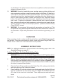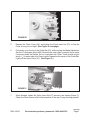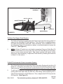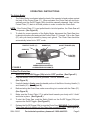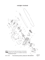
1
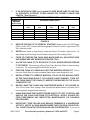
16” ELECTRIC Chain Saw
WITH BRAKE
Model 02810
ASSEMBLY AND OPERATING INSTRUCTIONS
®
3491 Mission Oaks Blvd., Camarillo, CA 93011
Visit our Web site at: http://www.harborfreight.com
Copyright© 2002 by Harbor Freight Tools®. All rights reserved. No portion of this
manual or any artwork contained herein may be reproduced in any shape or form
without the express written consent of Harbor Freight Tools.
For technical questions, please call 1-800-444-3353.
PRODUCT SPECIFICATIONS
Item
Electrical Requirements
Cutter Bar Size
Brake Stop
Chain Type
Oiler System
Chain Guide Rail
Dimensions
Weight
Description
2 HP / 120 V / 60 Hz / 13.2 Peak Amps,
7.8 No Load Amps / 1600 Watt
16”
Electromagnetic Stop Within .15 Sec. After Shutoff
#91VG “Oregon® Chain”
Automatic
16-1/8” Long x 2-1/2” Wide x 5/32” Thick
11 Pounds
SAVE THIS MANUAL
You will need this manual for the safety warnings and precautions,
assembly, operating, inspection, maintenance and cleaning
procedures, parts list and assembly diagram. Keep your invoice
with this manual. Write the invoice number on the inside of the front
cover. Keep this manual and invoice in a safe and dry place for
future reference.
GENERAL SAFETY WARNINGS AND PRECAUTIONS
1.
KEEP WORK AREA CLEAN AND DRY. Cluttered, damp, or wet work areas
invite injuries.
2.
KEEP CHILDREN AWAY FROM WORK AREA. Do not allow children to handle
this product.
3.
STORE IDLE EQUIPMENT. When not in use, tools and equipment should be
stored in a dry location to inhibit rust. Always lock up tools and equipment, and
keep out of reach of children.
4.
DO NOT USE THIS PRODUCT IF UNDER THE INFLUENCE OF ALCOHOL OR
DRUGS. Read warning labels on prescriptions to determine if your judgement or
reflexes are impaired while taking drugs. If there is any doubt, do not attempt to
use this product.
5.
USE EYE AND HEARING PROTECTION. Wear ANSI approved safety impact
eye goggles, full face shield and ANSI approved hearing protection (plugs or
muffs) during use. ANSI approved safety impact eye goggles and hearing protection are available from Harbor Freight Tools.
SKU 02810
For technical questions, please call 1-800-444-3353.
Page 2
6.
DRESS SAFELY. Do not wear loose clothing or jewelry, as they can become
caught in moving parts. Wear a protective hair covering to prevent long hair from
becoming caught in moving parts. Wear close fitting clothing and steel toed
shoes.
7.
DO NOT OVERREACH. Keep proper footing and balance at all times to prevent
tripping, falling, back injury, etcetera.
8.
INDUSTRIAL APPLICATIONS MUST FOLLOW OSHA REQUIREMENTS.
9.
STAY ALERT. Watch what you are doing at all times. Use common sense. Do
not use this product when you are tired or distracted from the job at hand.
10.
CHECK FOR DAMAGED PARTS. Before using this product, carefully check that
it will operate properly and perform its intended function. Check for damaged
parts and any other conditions that may affect the operation of this product. Replace or repair damaged or worn parts immediately.
11.
REPLACEMENT PARTS AND ACCESSORIES: When servicing, use only
identical replacement parts. Only use accessories intended for use with this
product. Approved accessories are available from Harbor Freight Tools.
12.
MAINTAIN THIS PRODUCT WITH CARE. Keep this product clean and dry for
better and safer performance.
13.
MAINTENANCE: For your safety, service and maintenance should be performed
regularly by a qualified technician.
14.
USE THE RIGHT TOOL FOR THE JOB. Do not attempt to force a small tool or
attachment to do the work of a larger industrial tool. There are certain applications for which this tool was designed. It will do the job better and more safely at
the rate for which it was intended. Do not modify this tool, and do not use this tool
for a purpose for which it was not intended.
15.
WARNING: The warnings, precautions, and instructions discussed in this manual
cannot cover all possible conditions and situations that may occur. The operator
must understand that common sense and caution are factors, which cannot be
built into this product, but must be supplied by the operator.
16.
WARNING: Take caution as some woods contain preservatives such as copper
chromium arsenate (CCA) which can be toxic. When cutting these materials extra
care should be taken to avoid inhalation and minimize skin contact.
SKU 02810
For technical questions, please call 1-800-444-3353.
Page 3
SPECIFIC PRODUCT WARNINGS AND PRECAUTIONS
1.
MAINTAIN A SAFE WORKING ENVIRONMENT. Make sure the work area is well
lit. Make sure there is adequate surrounding workspace. Always keep the work
area free of obstructions, tree limbs, vegetation, and other debris. Do not use the
Chain Saw in areas near flammable chemicals, dusts, and vapors. Do not use the
Chain Saw in a damp or wet location.
2.
DO NOT USE THE CHAIN SAW WITH ADULTS, CHILDREN, AND PETS IN
CLOSE PROXIMITY.
3.
ALWAYS HOLD THE CHAIN SAW FIRMLY WITH BOTH HANDS UNTIL THE
ROTATING CHAIN (57) COMPLETELY STOPS. MAKE SURE TO STAND IN A
STABLE, BALANCED POSITION WHEN USING THE CHAIN SAW. Avoid awkward postures.
4.
DO NOT USE THE CHAIN SAW IF THE CHAIN (57) IS DULL.
5.
BE AWARE OF THE DIRECTION OF THE ROTATION OF THE CHAIN (57). Chain
must move in the direction shown in Figure C, page 7.
6.
ALWAYS BE PREPARED FOR THE POSSIBILITY OF CHAIN SAW KICKBACK.
Kickback is a sharp, quick, upward movement of the Chain Saw when it is running.
This usually occurs when the upper/front quarter of the Guide Bar (52) binds with
the piece of wood being cut. In the event of a significant kickback, the Chain Safety
Brake may be automatically triggered, instantly stopping the rotating Chain (57)
and turning off the Chain Saw. The rotating chain may also be stopped by manually
pushing the Chain Safety Brake forward.
7.
ALWAYS CARRY THE CHAIN SAW BY ITS HANDLE (47) WITH THE CHAIN
(57) POINTING BACKWARDS AND THE CHAIN SAW A SAFE DISTANCE FROM
YOUR BODY. NEVER CARRY THE CHAIN SAW BY ITS ELECTRIC CORD (23).
KEEP HANDS AND FINGERS WELL AWAY FROM THE ON/OFF TRIGGER (25B)
WHILE CARRYING THE CHAIN SAW.
8.
MAKE SURE THE WOOD BEING CUT DOES NOT CONTAIN FOREIGN BODIES SUCH AS NAILS, SPIKES, STONES, ETC. DO NOT ATTEMPT TO CUT ANY
OTHER MATERIALS OTHER THAN WOOD.
9.
DO NOT ABUSE THE ELECTRIC CORD. Do not use the Electric Cord (23) to pull
its Plug from a power outlet or extension cord. Keep the Electric Cord away from
heat, water, oil, sharp edges, and moving parts. Do not route the Electric Cord
where it can be walked on or tripped over.
10.
KEEP ALL SAFETY GUARDS IN PLACE, IN PROPER ADJUSTMENT, AND IN
PROPER ALIGNMENT.
SKU 02810
For technical questions, please call 1-800-444-3353.
Page 4
11.
IF AN EXTENSION CORD (not included) IS USED, MAKE SURE TO USE ONLY
UL APPROVED, OUTDOOR, CORDS HAVING THE CORRECT GAUGE AND
LENGTH. (See Figure A.)
REQUIRED MINIMUM EXTENSION CORD GAUGE – 120 VOLT
NAMEPLATE
AMPERES
(At Full Load)
0-5
5.1 - 8
8.1 - 12
12.1 - 15
15.1 - 20
EXTENSION CORD LENGTH
0 - 25
Feet
16
16
14
12
10
25 - 50
Feet
16
16
14
12
10
50 -100
Feet
16
14
12
10
10
100 – 150
Feet
12
10
-
150– 200
Feet
12
-
FIGURE A
12.
REDUCE THE RISK OF ACCIDENTAL STARTING. Make sure the On/Off Trigger
(25b) is in the “OFF” position before plugging the Electric Cord into a grounded, 120
Volt, electrical outlet.
13.
NEVER pass hands or legs directly under the Chain (57) when cutting wood. Always keep hands and legs a safe distance away from the rotating Chain.
14.
PRIOR TO STARTING THE CHAIN SAW, MAKE SURE ALL ADJUSTING KEYS
AND WRENCHES ARE REMOVED FROM THE TOOL.
15.
ALLOW THE CHAIN (57) TO ROTATE UP TO FULL SPEED BEFORE FEEDING
IT INTO WOOD. When turning off the Chain Saw, allow the Chain to slow and stop
on its own. Do not press against the Chain to stop it.
16.
FEED THE CHAIN (57) GRADUALLY INTO THE MATERIAL BEING CUT. Do not
force the Chain Saw to remove material faster than it was designed to cut.
17.
NEVER ATTEMPT TO REMOVE MATERIAL STUCK IN THE MOVING PARTS
OF THE CHAIN SAW WHILE IT IS PLUGGED IN AND RUNNING. TURN OFF
THE CHAIN SAW IF THE CHAIN (57) NEEDS TO BE BACKED OUT OF AN UNCOMPLETED CUT.
18.
NEVER LEAVE THE CHAIN SAW UNATTENDED WHEN IT IS PLUGGED IN.
Turn off the Chain Saw, unplug it from its electrical power source, and wait until it
has completely stopped before leaving.
19.
ALWAYS RELEASE THE ON/OFF TRIGGER (25B) TO ITS “OFF” POSITION, AND
UNPLUG THE CHAIN SAW FROM ITS ELECTRICAL SUPPLY SOURCE BEFORE PERFORMING ANY INSPECTION, MAINTENANCE, OR CLEANING
PROCEDURES.
20.
IMPORTANT! TREE FELLING AND BRANCH TRIMMING IS A DANGEROUS
ACTIVITY. USE OF A CHAIN SAW REQUIRES THAT YOU BE IN GOOD PHYSICAL CONDITION, WITH GOOD BALANCE AND COORDINATION. If you are in
SKU 02810
For technical questions, please call 1-800-444-3353.
Page 5
any doubt about the safety issues involved, have a qualified, certified, arborist/tree
surgeon do the work for you.
21.
WARNING: Some dust created by power sanding, sawing, grinding, drilling, and
other construction activities, contain chemicals known (to the State of California) to
cause cancer, birth defects or other reproductive harm. Some examples of these
chemicals are: lead from lead-based paints, crystalline silica from bricks and cement or other masonry products, arsenic and chromium from chemically treated
lumber. Your risk from these exposures varies, depending on how often you do this
type of work. To reduce your exposure to these chemicals: work in a well ventilated
area, and work with approved safety equipment, such as those dust masks that are
specially designed to filter out microscopic particles. (California Health & Safety
Code § 25249.5, et seq.)
22.
WARNING: We recommend that people with pacemakers not use this tool. This
tool produces strong electromagnetic fields that can cause interference or failure of
the pacemaker. People with pacemakers should consult their physician(s) for advice.
UNPACKING
When unpacking, check to make sure all the parts shown on the Parts List on page 11
are included. If any parts are missing or broken, please call Harbor Freight Tools at the
number shown on the cover of this manual as soon as possible.
ASSEMBLY INSTRUCTIONS
NOTE: For additional references to the parts listed in the following pages, refer to the
Assembly Diagram on page 12.
To Attach Or Replace The Chain Guide Rail And Chain:
1.
WARNING: Make sure to turn the On/Off Trigger (25b) to its “OFF” position and unplug the Electric Cord (23) from its electrical outlet before performing this procedure.
2.
Remove Screw (7) and Nylon Insert Nut (67) from the Chain Cover (46) with the
tools provided. Note the Blade Guide Pin (62) and Bolt (6) shown in Figure B. Make
sure the Guide Pin is positioned near the rear (left end) of the slot. Make certain that
the oil port is open and free of debris.
3.
Place the Chain (57) around the rear of the Chain Gear (45), making certain that the
teeth along the top of the Chain point forward.
4.
Place Guide Bar (52) with the center slot over the threaded end of the Bolt (66), and
fixed pin (molded into the Front Cover (42)), as in Figure C. The Blade Guide Pin
(62) goes into the lower hole in the blade. These steps may be easier with assistance.
REV 05/05
SKU 02810
For technical questions, please call 1-800-444-3353.
Page 6
FIGURE B
5.
Replace the Chain Cover (46), and tighten the Nylon Insert Nut (67) so that the
Cover is snug, but not tight. (See Figure D, next page.)
6.
Pull gently up on the tip of the Guide Bar (52), while turning the Blade Adjustment
Screw (61) clockwise (photo 005.) Because the saw is light in weight, this is easier
if someone holds the handle. Do not overtighten the Chain. There should only be
about 1/4” of space when the Chain is pulled upward at the center of the Guide Bar.
Lightly oil the entire Chain (57). (See Figure C.)
FIGURE C
7.
When finished, tighten the Nylon Insert Nut (67) securely, and replace Screw (7).
Check the Chain tension after initial operation of the saw. It may need adjustment.
REV 05/05
SKU 02810
For technical questions, please call 1-800-444-3353.
Page 7
BLADE ADJUSTMENT
SCREW (61)
OIL FILL CAP (11)
ON/OFF TRIGGER (25b)
CHAIN (57)
FIGURE D
CHAIN COVER
(46)
NUT
(67)
GUIDE BAR (52)
To Check For Proper Chain Tension:
1.
The Chain (57) tension is proper when the Chain snaps back after being pulled 1/4”
away from the Guide Bar (52) with light force. There should be no sagging between
the Chain and Guide Bar underneath. When necessary, use a screwdriver to turn
the Adjustment Screw (61) clockwise to tighten, or counterclockwise to loosen, the
Chain (57). (See Figure D.)
2.
NOTE: A Chain (57) which is too taut leads to premature Chain and Guide Bar (52)
wear. A Chain which is too loose may jump out of the Guide Bar groove and damage the tool or cause personal injury. New chains typically lose tension initially
during use. When necessary, readjust the Chain tension by following the directions
in Step # 1 of this section.
To Refill The Automatic Chain Lubrication System:
1.
The Chain Saw features an automatic Chain Lubrication System with a built-in Oil
Reservoir. Lubrication of the Chain (57) is carried out automatically while the Chain
Saw is running. The oil level should be checked before each use of the Chain Saw.
2.
To refill the Oil Reservoir, unscrew the Oil Fill Cap (11). Fill the Oil Reservoir with a
quality grade chain saw Chain Oil (SAE 30). When filling, avoid introducing dirt or
other foreign material into the Oil Reservoir. Then, retighten the Oil Fill Cap onto the
Oil Reservoir. (See Figure D.)
REV 05/05
SKU 02810
For technical questions, please call 1-800-444-3353.
Page 8
OPERATING INSTRUCTIONS
The Safety Brake:
1.
The Safety Brake is activated when the back of the operator’s hand pushes against
the back of the Protect Plate (17). When activated, the Chain Saw will stop automatically, and the On/Off Trigger (25b) should be manually released. Next, pull the
Protect Plate (17) back to its initial position in order to restart the Chain Saw.
NOTE: If the Protect Plate (17) is not pulled back to its initial position, the Chain Saw will
not operate. (See Figure E.)
2.
To check for proper operation of the Safety Brake, disconnect the Chain Saw from
its electrical power outlet and push the Protect Plate (17) forward. Pull on the Chain
(57) with your hand protected by heavy work gloves. The Chain Saw should be
automatically locked in its “OFF” mode.
PROTECT PLATE (17)
HANDLE (47)
ON/OFF TRIGGER (25b)
CHAIN (57)
ELECTRIC
CORD (23)
CARBON BRUSH (4)
CARBON BRUSH HOLDER (5)
CARBON BRUSH HOUSING (6)
FIGURE E
To Start The Chain Saw:
1.
Make sure the On/Off Trigger (25b) is in its “OFF” position. (See Figure E.)
2.
Plug the Electric Cord (23) into a grounded, 120 volt, electrical outlet.
(See Figure E.)
3.
Use both hands to firmly grasp the handle portion of the Motor Housing Handle (1)
and Handle (47). (See Figure E.)
4.
Before starting the Chain Saw, make sure nothing is in contact with the Chain (57).
(See Figure E.)
5.
Make sure the Protect Plate (17) is pulled back towards your body until it “clicks”
and locks in place. (See Figure E.)
6.
To start the Chain Saw, push the Safety Switch on the On/Off Trigger (25b) and
squeeze the On/Off Trigger. (See Figure E.)
7.
Release the On/Off Trigger (25b) to stop the Chain Saw. WARNING: Firmly hold the
Chain Saw with both hands until the Chain Saw completely stops. (See Figure E.)
SKU 02810
For technical questions, please call 1-800-444-3353.
Page 9
INSPECTION, MAINTENANCE, AND CLEANING
1.
WARNING: Always turn the On/Off Trigger (25b) to its “OFF” position and unplug the
Electric Cord (23) from its electrical outlet before performing any inspection, maintenance, or cleaning. (See Figure E.)
2.
BEFORE EACH USE, inspect the general condition of the Chain Saw. Check for
loose screws, misalignment or binding of moving parts, cracked or broken parts
(i.e., Chain, 57), damaged electrical wiring, and any other condition that may affect
its safe operation. If abnormal noise or vibration occurs, have the problem corrected
before further use. Do not use damaged equipment.
3.
UPON EVERY THREE HOURS OF USE, make sure the Chain (57) is adequately
lubricated and taut. If necessary, remove the Guide Bar (52) and Chain. Clean the
groove in the Guide Bar thoroughly and clean the Oil Port in the Front Cover (42) to
ensure that it is not blocked or obstructed, see Figure B. To maximize the life of the
Guide Bar, turn the Guide Bar over and then reinstall. (See Figures C and D.)
4.
PERIODICALLY, remove the Carbon Brush Housing (6) to inspect the condition of
the Carbon Brush (4). If the Carbon Brush is simply dirty, you may carefully clean it
with a pencil eraser. The Carbon Brush has a wear limit marking on it. You may
safely use the Carbon Brush up to the wear limit. When it has worn up to the wear
limit, the Carbon Brush must be replaced. When replacing the Carbon Brush make
sure it fits neatly into its Carbon Brush Holder (5) and that the spring on the Carbon
Brush operates freely. Make sure the carbon portion of the Carbon Brush contacts
the Motor Armature (24). After inspection or replacement, replace the Carbon Brush
Housing. (See Figure E.)
5.
TO CLEAN: Clean with a soft brush, cloth, or vacuum to remove debris from the
Cold Saw. If necessary, use a mild detergent or mild solvent. Then, use a premium
quality, lightweight machine oil to lubricate all moving parts.
6.
If cutting efficiency diminshes, the included round file may be used to sharpen the
teeth of the chain. The chain should also be sharpened professionally at least once
a year, depending on use.
PLEASE READ THE FOLLOWING CAREFULLY
THE MANUFACTURER AND/OR DISTRIBUTOR HAS PROVIDED THE PARTS DIAGRAM IN THIS MANUAL AS A
REFERENCE TOOL ONLY. NEITHER THE MANUFACTURER NOR DISTRIBUTOR MAKES ANY REPRESENTATION OR WARRANTY OF ANY KIND TO THE BUYER THAT HE OR SHE IS QUALIFIED TO MAKE ANY REPAIRS TO
THE PRODUCT OR THAT HE OR SHE IS QUALIFIED TO REPLACE ANY PARTS OF THE PRODUCT. IN FACT, THE
MANUFACTURER AND/OR DISTRIBUTOR EXPRESSLY STATES THAT ALL REPAIRS AND PARTS REPLACEMENTS SHOULD BE UNDERTAKEN BY CERTIFIED AND LICENSED TECHNICIANS AND NOT BY THE BUYER.
THE BUYER ASSUMES ALL RISK AND LIABILITY ARISING OUT OF HIS OR HER REPAIRS TO THE ORIGINAL
PRODUCT OR REPLACEMENT PARTS THERETO, OR ARISING OUT OF HIS OR HER INSTALLATION OF REPLACEMENT PARTS THERETO.
SKU 02810
For technical questions, please call 1-800-444-3353.
Page 10
PARTS LIST
Part
Description
Q'ty
Part
Description
Q'ty
1
Motor housing
1
32
Brake plate
1
2
Rear cover
1
33
Brake block
1
3a
Screw ST4.2*18
10
34
Brake belt
1
3b
Flat washer
11
35
Pinion gear
1
4
Carbon brush
1
36
Connection rod
1
5
Carbon brush holder
1
37
Terminal
1
6
Carbon brush housing
1
38
Torsion spring
1
7
Screw ST5*20
5
39
Switch
2
8
Screw ST3*16
4
40
Bearing 608
1
9
Screw ST5*30
2
41
Big gear
1
10
Stator
1
42
Front cover
1
11
Oil bottle
1
43
Screw M6*35
1
13
Oil pipe
1
44
Nut M6
1
14a
Oil pump 1
1
45
Chain gear
1
14b
Steel ball dia.3.5
1
46
Chain cover
1
14c
Oil pump spring
1
47
Side handle
1
14d
Oil pump pressure plate
1
49
Screw ST5*35
1
14e
Oil pump pull rod
1
50
Screw ST5*22
1
14f
Oil pump 2
1
51
Housing
1
15
Screw M4*10
2
52
Guide bar
1
16
Stop spring
1
54
Bearing 609
1
17
Protect plate
1
55
Bearing
1
18
Pin 5*25
1
56
Screw ST5*22
1
19
Winding Cover
1
57
Chain
1
20
Bearing 608
1
58
Pin 4*7
1
21
Brake anchor pin
1
59
Rubber terminal
2
22
Brake lock
1
60
Screw ST4*16
1
23
Electric cord
1
61
Blade adjustment screw M5*30
1
24
Armature
1
62
Blade guide pin
1
25a
Trigger stop rod
1
63
Spring washer
3
25b
Trigger
1
64
Flat washer
2
25c
Trigger spring
1
65
Nut M10
1
27
Cord guard
1
66
Hex bolt M8*25
1
28
Capacitor
1
67
Nylon inser t nut M8
1
29
Screw ST4.2*14
3
68
Side cover
1
30
Cord anchorage
1
69
Retaining Ring
1
REV 05/05
SKU 02810
For technical questions, please call 1-800-444-3353.
Page 11
ASSEMBLY DIAGRAM
NOTE: Some parts are listed and shown for illustration
purposes only, and are not available individually
as replacement parts.
REV 05/05
SKU 02810
For technical questions, please call 1-800-444-3353.
Page 12