1
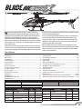
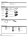
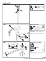
®
Instruction Manual
Bedienungsanleitung
Manuel d’utilisation
Manuale di Istruzioni
®
®
NOTICE
All instructions, warranties and other collateral documents are subject to change at the sole discretion of Horizon Hobby, Inc. For up-to-date product literature, visit
horizonhobby.com and click on the support tab for this product.
Meaning of Special Language
The following terms are used throughout the product literature to indicate various levels of potential harm when operating this product:
The purpose of safety symbols is to atttract your attention to possible dangers. The safety symbols, and their explanations, deserve your careful attention and
understanding. The safety warnings do not by themselves eliminate any danger. The instructions or warnings they give are not substitutes for proper accident
prevention measures.
NOTICE: Procedures, which if not properly followed, create a possibility of physical property damage AND a little or no possibility of injury.
CAUTION: Procedures, which if not properly followed, create the probability of physical property damage AND a possibility of serious injury.
WARNING: Procedures, which if not properly followed, create the probability of property damage, collateral damage, serious injury or death OR create a high
probability of superficial injury.
Safety Alert: Indicates warning or caution. Attention is required in order to avoid serious personal injury.
WARNING: Read the ENTIRE instruction manual to become familiar with the features of the product before operating. Failure to operate the product correctly
can result in damage to the product, personal property and cause serious injury.
This is a sophisticated hobby product for advanced helicopter pilots with previous experience in the operation of CCPM helicopters (Cyclic Collective Pitch Mixing
or Collective Pitch Helicopter) such as the Blade SR, Blade mCP X or Blade 300 X. It must be operated with caution and common sense and requires some basic
mechanical ability. Failure to operate this product in a safe and responsible manner could result in injury or damage to the product or other property. This product is
not intended for use by children without direct adult supervision. Do not use with incompatible components or alter this product in any way outside of the instructions
provided by Horizon Hobby, Inc. This manual contains instructions for safety, operation and maintenance. It is essential to read and follow all the instructions and warnings in the manual, prior to assembly, setup or use, in order to operate correctly and avoid damage or serious injury.
Age Recommendation: For advanced fliers ages 14 and above. This is not a toy.
General Safety Precautions and Warnings
This model is controlled by a radio signal subject to interference from many sources outside your control. Interference can cause momentary
loss of control.
• Always ensure you fully understand the controls on your transmitter and how they affect the movement of the helicopter.
• Always operate your model outdoors in large, open spaces away from full-size vehicles, traffic and people to avoid collisions or injury
• Always carefully follow the manufacturers directions and warnings for any related equipment (i.e., chargers, rechargeable battery packs, etc.).
• Always keep the product, related chemicals, small parts and electrical components out of the reach of children.
• Always keep children out of the vicinity of this product at all times.
• Always store this product well out of the reach of children.
• Always keep hair secured above your shoulders so it cannot get caught in the blades.
• Always avoid water exposure to all equipment not specifically designed and protected for this purpose. Moisture causes damage to electronics.
• Never maintain and operate this product at night, in rain or in inclement weather.
• Always ensure all fasteners are secure before use.
• Always store product in a dry, temperate, secure location
• Do not touch the motor as it can become extremely hot during use.
• Do not fly this helicopter indoors
• Always ensure failsafe is properly set before flying. Do not exclusively rely on the safety mechanisms built into your transmitter and receiver.
• Always ensure you understand the product and how to operate it.
• Only use Horizon-approved replacement parts and accessories for this product.
• Never place any portion of the model in your mouth as it could cause serious injury.
• Never operate your transmitter or helicopter with low transmitter batteries.
• Never connect the battery unless using or testing the product. Do not perform maintenance with the battery installed.
• Never operate this product if you are tired, ill, taking any medications that impair judgment or are under the influence of alcohol or drugs.
• Never spray glass cleaner or any other liquid on this product.
• Always keep hair and dangling or loose items well away from the blades when the battery is connected.
WARNING: This is a large model helicopter with carbon fiber blades that spin at very high RPM. Always use extreme caution and common sense when
maintaining and operating this product. If you are unsure about ANY function or procedure described in this manual, DO NOT operate. Contact Horizon
Product Support for assistance.
WARNING: Always ensure you are operating the helicopter a safe distance, 45 feet (13 meters), away from yourself and others.
EN
2
®
elcome to the world of Blade® Pro Series helicopter performance.
Over two decades of flying and design experience has gone into the
development of the Blade 600 X. Starting with the impressive 6S powered
Blade 550 X, the Blade 600 X packs a monster 12S Li-Po pack with a
700-sized motor into a stretched airframe to accommodate 600mm rotor
blades. Every part, down to the nuts and bolts, has been chosen or designed
with one goal in mind—giving you a no compromise, 600-size 3D machine
that is second to none.
Every step is clearly illustrated and shows what parts are needed to complete
it. You’ll find helpful building tips too.
W
If this is your first helicopter building experience, there are a few things you
might want to get before you start unpacking parts. Many builders prefer
to lay out a towel or a rubber mat to prevent screws from bouncing off the
worktable. It’s also a good idea to use small containers to keep parts organized after you take them out of the bags.
Before you tear into the contents of this box, however, you must review this
manual. It’s been written and designed to make assembling the Blade 600 X
one of the most enjoyable, hassle-free building experiences you’ll ever have.
Most importantly, take your time. Review every assembly step and make
sure you understand how the parts fit before you start bolting things together.
When you’re done, you’ll have a capable, smooth-flying helicopter that flies
exactly as it was designed to.
Table of Contents
Tools Needed to Complete ..................................................................................4
Required Items ...................................................................................................4
Optional Items ....................................................................................................4
Assembly Guide ..................................................................................................4
Head Assembly (H) ..............................................................................................5
Frame Assembly (F) ............................................................................................7
Tail Assembly (T) ...............................................................................................10
Electronics Installation ......................................................................................13
Servo Arms and Links Installation .....................................................................15
Main Rotor Installation ......................................................................................15
Canopy Installation ...........................................................................................15
Programming Your Transmitter ..........................................................................16
Throttle Hold .....................................................................................................16
AR7200BX Setup ..............................................................................................17
AR7200BX Parameter Menu Tips ......................................................................17
Motor Direction Test ..........................................................................................17
Blade 600 X Specifications
Tail Rotor Diameter
46.06 in (1170mm)
Length
Height
Main Rotor Diameter
Motor
ESC
BEC
Battery
Charger
Control Test.......................................................................................................18
Low Voltage Cutoff ............................................................................................20
Flight Guidelines and Warnings .........................................................................20
Flying Your 600X ...............................................................................................20
Blade Tracking ..................................................................................................21
Adjusting the Rudder Gain.................................................................................21
Post Flight Inspection and Maintenance Checklist .............................................21
AR7200BX Fine-Tuning and Adjustment ............................................................21
Troubleshooting Guide ......................................................................................22
Limited Warranty ..............................................................................................23
Customer Service Information ...........................................................................24
Compliance Information for the European Union ................................................25
Exploded Views ......................................................................................... 98-100
Parts List / Ersatzteile / Pièces de rechange / Pezzi di ricambio ............... 101-103
Optional Parts / Optionale Bauteile / Pièces optionnelles / Pezzi opzionali ...........103
Flying Weight
10.8 in (275mm)
52.95 in (1345mm)
Component
Heli 700 Brushless Outrunner
Motor, 500Kv
100-Amp HV Brushless
10-Amp BEC
(2) 6S 22.2V 3200mAh
30C or higher Li-Po
DC Li-Po Balancing Charger
Kit
Combo
included
included
included
included
included
included
required
required
required
required
10.03 in (255mm)
8.35-8.8 lb (3800-4000g)
Component
DSM2®/DSMX® compatible
Transmitter
transmitter
AR7200BX 7CH DSMX
Receiver
Flybarless Control System
Swash Servos Spektrum™ H6040
Tail Servo
Spektrum H6080G
Kit
Combo
required
required
required
included
required
required
included
included
To register your product online, visit www.bladehelis.com
3
EN
Tools Needed To Complete
• 1.5mm, 2mm, 2.5mm, and 3mm hex drivers
• Ball link pliers
• Needle nose pliers
• Phillips screwdriver
• Wire cutter
• Pitch gauge
• Metric calipers
• Petroleum based, light viscosity lube
• Medium cyanoacrolate (CA)
Required Items
Items included in the combo kit
• (2X) 3200mAh 6S 22.2V 30C LiPo,
10AWG with EC3™ connector
(EFLB32006S30)
• E-flite® EC3 Device Charge Lead
with 12” Wire & Jacks, 16 AWG
(EFLAEC312)
• AR7200BX Receiver/
Flybarless control unit
(SPMAR7200BX)
• DSMX Remote
Receiver (SPM9645)
• E-flite 200W charger (EFLC3020)
• (3) H6040 servos
(SPMSH6040)
• Celectra™ 15VDC 250W
Power Supply (EFLC4010)
• (1) H6080G tail servo
(SPMSH6080G)
• DSM2®/DSMX® compatible DX6i 6 channel
transmitter or higher
Optional Items
• Dynamite® Li-Po Charge
Protection Bag, Large
(DYN1405)
• Control Rod Set Up Tool
(RVO1004)
Assembly Guide Legend
Apply BLUE Threadlock
OIL
Apply NO Threadlock
Apply Petroleum based,
light viscosity lube
Loosely Tighten
Apply Synthetic Grease
Fully Tighten
Apply MEDIUM CA
EN
4
2X
Repeat Multiple Times
Head Assembly (H)
Step H1 parts (bags H1 and H2)
Step H1
M4 X 22 cap head
shoulder bolt
M4 locknut
22mm
Step H2
Step H2 parts (bag H1)
M3 X 18 cap head
shoulder bolt (x2)
M2 X 5 cap head bolt (x4)
Step washer (x4)
• The stepped sides of the washers should face the
radial bearings.
2X
Step H3
• Do not over-tighten. The follower arms should move
freely.
Step H3 parts (bags H1 and H2)
Center sleeve
on the spindle
Damper
Damper (x2)
Spindle sleeve
M3 X 8 cap head bolt
• Clean the threads in the spindle thoroughly with
alcohol before installation.
Damper
5
EN
Head Assembly cont’d
Step H4 parts (bag H3)
Step H4
2X
Thrust bearing (x2)
Thrust washer
10 X 14 X .8 (x2)
B
Spindle bolt washer
Thrust washer
Spindle bolt washer
4 X 12 X 1 (x2)
Step washer (x2)
C
Step washer
A
Larger I.D. thrust washer race
Bearing cage
Smaller I.D. thrust washer race
Smaller inner
diameter (I.D.)
A
M4 X 12 bolt (x2)
B
M3 X 14 bolt (x2)
C
M3 X 8 bolt (x2)
Control ball (x2)
• Loosely install bolts B and C before tightening.
• The stepped washer faces the radial bearing in the
blade grip.
Step H5 parts (bag H4)
EN
A
Step H5
6
Larger inner
diameter (I.D.)
Frame Assembly (F)
ASSEMBLY NOTE: Before assembly, plan your wire routing for the servos. At any point where the servo wire is going to pass through or cross the frame plates,
use sandpaper to round the edge of the frame plate to prevent the wire from chafing.
Step F1 parts (bags F1, F2, and F3)
Step F1
A
B
A
Cap head bolt
M3 X 10 (x4)
B
Cap head bolt
M3 X 14 (x4)
C
Self tapping screw
M3 X 8 (x4)
M3 recessed washer (x8)
C
• At this stage of the assembly, do not tighten
the bearing blocks or bottom plate screws.
C
B
Top block
A
C
Middle block
C
Step F2
A
Step F2 parts (bag F5)
A
Button head screw
M3 X 12 (x6)
B
Self tapping screw
M3 X 12 (x4)
Servo washers (x10)
A
A
4X
B
B
7
EN
Frame Assembly cont’d
Step F3 parts (bags F3 and F5)
A
B
Step F3
Setscrew
M3 X 11 (x2)
Button head screw
M3 X 12 (x6)
Cap head bolt
M3 X 10 (x4)
Canopy
mounting post (x2)
M3 Washer (x6)
M3 Recessed
washer (x4)
• Slide the mainshaft into position, then tighten all the
frame and servo screws.
B
A
A
B
A
Step F4 parts (bag F4)
Step F4
Button head screw
M3 X 12 (x4)
M3 Recessed washer (x4)
Self tapping screw
M3 X 8 (x4)
EN
8
Frame Assembly cont’d
Step F5
Step F5 parts (bag M1)
Washer (x1)
One way sleeve (x1)
Shoulder cap head bolt
M4 X 22
M4 Lock nut
Counter sunk self tapping
screw M3 X 8 (x5)
Setscrew M3 X 4 (x2)
Step F6
Step F6 parts (bag F6)
6mm, 18 tooth pinion gear
Setscrew M3 X 4 (x2)
Cap head bolt M4 X 10 (x4)
Cap head bolt M3 X 10 (x4)
M4 Washer (x4)
M3 Recessed washer (x4)
3mm
9
EN
Tail Assembly (T)
Step T1 parts (bag T1)
Step T1
Hexagonal posts (x6)
Radial bearing
12 X 18 X 4 (x2)
Radial bearing
5 X 10 X 4 (x2)
Brass spacer
Cap head shoulder
bolt M3 X 18 (x4)
M3 Lock nut (x4)
Step T2 parts (bag T1)
Step T2
Button head self tapping
screw M3 X 12 (x12)
EN
10
Tail Assembly cont’d
Step T3
Step T3 parts (bags T2 and T3)
A
C
A
Cap head bolt M3 X 10 (x2)
B
Cap head bolt M3 X 8 (x4)
C
Button head screw
M3 x 10 (x2 )
B
M3 Recessed washer (x2)
B
B
B
Step T4
Step T4 parts (bags T4 and T5)
Small inner diameter race
2X
Tail blade bolt (x2)
Bearing cage
Large inner diameter race
Tail blade nut (x2)
Thrust bearing (x2)
B
A
A
Thrust washer (x2)
Control ball (x2)
M4 x 3 Set screw
M3 X 8 Cap head
bolt (x2)
B
11
M3 Washer (x2)
EN
Tail Assembly cont’d
Step T5 parts (bag T6)
Step T5
Button head screw
M3 X 5 (x2)
Cap head bolt M3 X 25
M3 Step washer (x4)
Control ball
M3 Lock nut
• The stepped side of the washer faces the radial
bearing.
Tail rotor blade
removed for clarity
viewed from back
Step T6a parts (bag T7)
Step T6a
Button head screw
M3 X 12 (x2)
M3 Lock Nut (x2)
• Slide the torque tube bearings onto the torque tube
and glue them in place by placing a thin bead of CA
on the torque tube at the given locations (200mm,
226mm), then slide the bearings onto the CA. Do not
allow CA to get into the bearings.
• Use oil on the outside of the torque tube bearing
holders to ease installation into the boom.
214 mm
226 mm
OIL
OIL
EN
12
200 mm
Tail Assembly cont’d
Step T6b
Step T6b parts (bags T8 and T3)
viewed
from back
A
B
A
90°
Self tapping screw
M3 X 12 (x6)
Self tapping screw
M2.5 X 8 (x2)
M3 Recessed washer (x6)
viewed from left
Ball link (x2)
A
120 mm
Rear pushrod guide insert
Front pushrod guide insert
230 mm
A
B
A
B
A
Front
Rear
Electronics Installation (E)
Flybarless Control Unit and Remote Receiver
Step E1 parts (bag E1)
Cap head
M3 X 10 (x4)
Recessed washer (x4)
Counter sunk screw
M3 X 8 (x2)
AR7200BX servo connections
BIND/DAT Bind plug, telemetry module or data
logger (optional)
AUX2
BEC
AUX3
BEC
THRO
Speed control
Rx L
Remote receiver
ELEV
Center swashplate servo
AILE
Left swashplate servo
AUX1
Right swashplate servo
RUDD
Tail servo
Double-sided
foam tape
AR7200BX Alignment
TIP: Connect the remote receiver before plugging in the
servo leads.
90°
Front
viewed from top
13
EN
Electronics Installation cont’d
AR7200BX Arming
Speed control and BEC
1. Lower the throttle.
2. Power on the transmitter.
3. Center the throttle trim.
4. Turn throttle hold ON.
5. Attach hook material to the helicopter frame and
loop material to the battery.
6. Install the flight battery on the helicopter frame.
Secure the flight battery with a hook and loop
strap.
7. Connect the battery cable to the ESC.
8. Do not move the helicopter until the AR7200BX
initializes. The swashplate will move up and down,
indicating that the unit is ready. The AR7200BX will
also emit a solid BLUE Status LED when it is ready
9. The helicopter motor will emit a series of tones,
indicating the ESC is armed.
CAUTION: Always disconnect the Li-Po battery
from the aircraft receiver when not in use to
avoid over-discharging the battery. Batteries discharged to a voltage lower than the lowest approved
voltage may become damaged, resulting in loss of performance and potential fire when batteries are charged.
Double-sided foam tape
Hook and loop
material
Flight battery
To ESC
–+
EC5
EC2
To BEC
+
–
–+
EC3
To battery 1
–+
EC3
To battery 2
Loop material
Hook material
Hook and loop
strap
EN
14
Servo Arms and Links Installation (bag E2)
Servo ball link placement
Self tapping screw
M3 X 8 (x2)
Tail servo
Rear swash Front swash
servos (x2)
servo
g
Tail ppushrod alignment
A
A
Tail pitch bellcrank
neutral position
(viewed from the bottom)
Tail servo arm
neutral position
(viewed from the right side)
Pushrod lengths
g
68mm
B
B
A
Swash to blade grip link, 68mm (x2)
B
56mm
B
Servo to swash link, 56mm (x3)
Main Rotor Installation
Main Rotor Blades
Main Rotor Blade parts (bag E2)
Main blade shoulder bolt M4 X 25 (x2)
2X
M4 Lock nut (x2)
• The rotor blades should be tight enough to hold their
position if you hold the helicopter sideways, but loose
enough to swing freely if you move the helicopter
and stop abruptly.
15
EN
Programming Your Transmitter
Program your transmitter before attempting to bind or fly the helicopter. Transmitter programming values are shown below for the Spektrum DX6i, DX7/DX7se,
DX7s, DX8, and DX18. The files for models using Spektrum TM transmitters with AirWare™ software are also available for download online in the Spektrum Community.
DX6i
DX7/DX7se
SETUP LIST
ADJUST LIST
Model Type
HELI
Reverse
THRO N
AILE R
ELEV R
RUDD N
GYRO N
PITC R
Swash Type
1 Servo 90
Timer
4:00
D/R & Expo
0-AILE
0-ELEV
0-RUDD
1-AILE
1-ELEV
1-RUDD
Thro Curve
NORM
STUNT
HOLD
Pitc Curve
NORM
STUNT
HOLD
Travel Adj
THRO
AILE
ELEV
RUDD
GYRO
PITC
100%
100%
100%
85%
85%
85%
FUNCTION MODE
D/R & EXP
0-AILE
100% 0%
0-ELEV
100% 0%
0-RUDD
100% INH
1-AILE
85% 0%
1-ELEV
85% 0%
1-RUDD
85% INH
Thro Curve
NORM
0%
25% 25% 25%
ST-1
75% 75% 75% 75%
ST-2
100% 100% 100% 100%
HOLD
0%
0%
0%
0%
Pitc Curve
NORM
30% INH
50% INH
ST-1
0%
INH
50% INH
ST-2
0%
INH
50% INH
HOLD
0%
INH
50% INH
Reversing SW
Travel Adj
THRO N
RUDD N
THRO 100%
AILE R
GEAR N
AILE 100%
ELEV R
PIT.
N
ELEV 100%
RUDD 100%
Gyro SENS
GEAR 100%
AUTO F.MODE
PIT.
100%
STNT 71.5%
HOLD 71.5%
SYSTEM LIST
Model Type
HELI
0%
0%
INH
0%
0%
INH
Swash Type
1 Servo 90
0%
25% 25% 25% 25%
100% 100% 100% 100% 100%
10% 10% 10% 10% 10%
30%
0%
0%
40% 50% 75% 100%
25% 50% 75% 100%
25% 50% 75% 100%
Gyro
Rate
SW-F. Mode
100%
NORM
71.5%
100%
STUNT 71.5%
100%
100%
100%
100%
25%
75%
100%
0%
100%
100%
100%
100%
Timer
4:00
DX7s/DX8/DX18
SYSTEM SETUP
Model Type
HELI
Swash Type
1 Servo Normal
F-Mode Setup
Flight Mode: F Mode
Hold: Hold
Frame Rate
11ms
DSMX
FUNCTION LIST
D/R & Expo
0-AILE
100%
0-ELEV
100%
0-RUDD 100%
1-AILE
85%
1-ELEV
85%
1-RUDD 85%
2-AILE
85%
2-ELEV
85%
2-RUDD 85%
SERVO SETUP
Travel
THRO 100%
AILE 100%
ELEV 100%
RUDD 100%
GEAR 100%
PIT.
100%
0%
0%
0%
0%
0%
0%
0%
0%
0%
Reverse
THRO N
AILE
R
ELEV
R
RUDD N
GEAR N
PIT.
N
Throttle Curve
NORM
ST-1
ST-2 (DX8/18 only)
HOLD
Pitch Curve
NOR
ST-1
ST-2 (DX8/18 only)
HOLD
Timer
MODE
TIME
START
POS
0%
75%
100%
0%
25%
75%
100%
0%
25%
75%
100%
0%
25%
75%
100%
0%
25%
75%
100%
0%
30%
0%
0%
0%
40%
25%
25%
25%
50%
50%
50%
50%
75%
75%
75%
75%
100%
100%
100%
100%
Countdown
4:00 Tone/Vibe
Throttle Out
25
Gyro
SW
CH
NORMAL/POS 0
STUNT 1/POS 1
STUNT 2/POS 2
HOLD
F Mode
Gear
68%
68%
68%
68%
Throttle Hold
When you move the throttle hold switch to the ON position, the helicopter motor
turns off. You will still have control of the helicopter cyclic and rudder commands.
The blades spin if throttle hold is OFF. For safety, turn throttle hold ON any time
you need to touch the helicopter or check the direction controls.
IMPORTANT: the speed control shipped with your Blade 600 X is pre-programmed for this helicopter. If you wish to use the auto rotation bailout feature in
the speed control, follow this process.
1. Disengage the motor by either removing the pinion gear or sliding the motor
so the pinion does not engage the main gear.
You should also turn throttle hold ON to minimize damage if the helicopter is out
of control or in danger of crashing.
2. Power on your transmitter and then plug the battery into the speed control.
3. Activate throttle hold
4. Increase the throttle hold value until the motor begins to turn. Reduce the
value until the motor stops.
See your transmitter manual for more information on programming throttle hold.
EN
16
AR7200BX Recommended Blade 600 X Setup
Firmware version 3.X.X
SETUP MENU Menu LED solid
Status-LED:
Refer to the Spektrum AR7200BX manual for specific details.
OFF
Purple
Red Flashing
Red Solid
Blue Flashing
upright
(vertical)
A
Mounting orientation
B
Swashplate servo - frequency
User defined
50 Hz
C
Tail servo - center position pulse length
User defined
960 μs
D
Tail servo - frequency
User defined
50 Hz
E
Tail servo - rotor endpoints
Tail stick - move to right endpoint and wait/left endpoint and wait
F
Tail - sensor direction
65 Hz
120 Hz
flat (horizontal)*
165 Hz
760 μs
165 Hz
270* Hz
333 Hz
reversed*
AIL center pos.
PIT center pos.
Swashplate - servo centering
H
Swashplate - mixer
User defined
mechanical
I
Swashplate - servo directions
nor|rev|rev
nor|nor|rev*
J
Swashplate - cyclic pitch geometry
Aileron stick – adjust 6° cyclic pitch on the roll axis (blades aligned with fuselage)
K
Collective pitch range
Collective stick on max and min position and use tail stick to adjust desired pitch.
Stock settings provide +/- 14 degrees of collective pitch.
L
Swashplate - cyclic limit
Move aileron, elevator and pitch sticks – adjust max limits with tail stick
M
Swashplate - sensor directions
rev | rev
N
Pirouette optimization direction
120°*
140°
nor|rev|nor
rev | nor
560 Hz
normal
G
90°
200 Hz*
1520 μs*
Reference
position
ELE center pos.
Blue Solid
140° (1=1)
nor|nor|nor
nor | rev
nor | nor*
normal
reversed*
PARAMETER MENU Menu LED is flashing quickly
Status-LED:
A
B
C
Swashplate cyclic center adjustment
Control behavior
Swashplate - pitching up behavior
D
E
F
G
H
OFF
Purple
Red Flashing
Red Solid
Blue Flashing
Blue Solid
Aileron and elevator stick – reset with tail stick
User defined
normal
sport*
pro
extreme
transmitter
User defined
very low
low
medium*
high
very high
Tail - HeadingLock gain
Stick deadband
Tail - torque precompensation
Cyclic response
User defined
User defined
User defined
very low
1
off*
medium*
3
high - nor
high
4
low - rev
very high
5
high - rev
User defined
normal*
increased
high
very high
Pitch boost
User defined
off*
low
2*
low - nor
slightly
increased*
low
medium
high
very high
AR7200BX Parameter Menu Tips
Refer to the Spektrum AR7200BX manual to fine tune the Blade 600 X to your
flying and control style via the AR7200BX parameter menu.
If you would like to have the cyclic behavior to feel more linear OR more like
a flybarred helicopter, increase the cyclic response by adjusting parameter G
(default is ‘normal’).
If you would like to change the control behavior of the flybarless system to a
pre-defined behavior in the AR7200BX, adjust parameter B (default behavior is
transmitter).
Refer to the Spektrum AR7200BX manual for specific details on each
parameter.
Motor Direction Test
Place the helicopter outdoors on a clean, flat and level surface (concrete or
asphalt) free of obstructions. Always stay clear of moving rotor blades.
3. Connect the Li-Po battery to the ESC.
4. Turn TH HOLD OFF. Slowly increase the throttle until the drive train begins to
turn. The main blades spin clockwise when viewing the helicopter from the top.
The tail rotor blades spin counterclockwise when viewing the helicopter from
the right-hand side.
1. Power on the transmitter. Make sure TH HOLD is ON and the flight mode
switch is in the normal position.
WARNING: The motor will spin when throttle is increased
and TH HOLD is OFF.
NOTICE: If the drive train does not turn with the motor or spins counterclockwise,
turn TH HOLD ON. Disconnect the battery from the helicopter and reverse any
two motor wire connections to the ESC and repeat the motor control test.
2. Lower the throttle completely.
WARNING: Stay at least 45 feet (13 meters) away from
the helicopter when the motor is running.
17
EN
Control Tests
Neutral (Viewed from left)
Swashplate set to 0° (Neutral)
Positive pitch (Viewed from left)
Collective pitch
Mode 1
EN
Negative pitch (Viewed from left)
Mode 2
18
Neutral (Viewed from back)
Forward elevator (Viewed from left)
Elevator
Back elevator (Viewed from left)
Mode 1
Mode 2
Mode 1
Mode 2
Right aileron (Viewed from back)
Aileron
Left aileron (Viewed from back)
19
EN
Low Voltage Cutoff (LVC)
Low voltage cutoff (LVC) protects the Li-Po battery from overdischarge in flight
and activates when the battery reaches 3V per cell under load.
Set your transmitter timer for 4 minutes and land when the timer expires.
Repeatedly activating LVC damages the flight battery and you will need to
replace the battery.
Crash damage and battery damage are not covered under warranty.
Always disconnect and remove the Li-Po battery from the aircraft after each
flight. Charge your Li-Po battery to about half capacity before storage. During
storage, make sure battery charge does not fall below 3V per cell. A connected
battery will result in trickle discharge.
Flight Guidelines and Warnings
• Always keep aircraft in sight and under control.
• Always keep people and pets at least 45 feet (15 meters) away when the
battery is connected.
• Keep children out of the vicinity of this product at all times.
• Always turn on throttle hold at rotor strike.
• Always use fullly charged batteries.
• Always keep transmitter powered on while aircraft is powered.
• Always remove batteries before disassembly.
• Always keep moving parts clean.
• Always keep parts dry.
• Always let parts cool after use before touching.
• Always remove batteries after use.
• Always have a first aid kit with you.
• Always have an appropriate fire extinguisher with you.
• Never operate aircraft with damaged wiring.
• Never touch moving parts.
Flying Your 600X
CAUTION: Always fly the helicopter with your back to the sun and wind to
prevent loss of flight control.
Consult local laws and ordinances before choosing a location
to fly your aircraft.
Select a large, open area away from people and objects. Your first flights should
be outdoors in low-wind conditions. Always stay at least 45 feet (15 meters)
away from the helicopter when it is flying.
Do not attempt to fly the Blade 600 X indoors.
CAUTION: The Blade 600 X is intended for pilots with experience flying
aerobatic, collective pitch helicopters. The Blade 600 X is more responsive
than other Blade helicopters. If you are not an experienced 3D or collective pitch
helicopter pilot, do not attempt to fly this product.
Takeoff
Gradually increase the throttle, allowing the rotors time to come up to speed.
CAUTION: Do not give any aileron, elevator or rudder commands before the
helicopter lifts off. Any control inputs prior to liftoff could cause a crash.
The helicopter will lift off the ground when the rotor head reaches a suitable
speed and you apply collective pitch. Once airborne, establish a low-level hover
to verify everything is functioning properly. DO NOT use trim to assist in holding
the Blade 600 X in a desired position. The AR7200BX Flybarless Stabilization
System renders trim unnecessary by working to keep the helicopter in whatever
attitude you command with the control sticks.
Flying
This aircraft is extremely sensitive to control inputs. We recommend you fly at
low rate settings for the first few flights until you are familiar with its response.
For pilots new to collective pitch helicopters, familiarize yourself with your Blade
600 X in normal mode and at low rate.
EN
Landing
Establish a low level hover. Deliberately lower the throttle until the helicopter
lands. Make only small control corrections during this time to avoid rotor blade
strikes or other damage.
When the helicopter is in stunt mode:
• The rotor head speed is constant.
• The main rotor will increase negative pitch as the throttle/collective stick is
moved from the middle stick position to the low stick position. Negative pitch
allows the helicopter to fly upside down and perform aerobatics.
Change between stunt and normal modes in a hover with the throttle near the
hovering stick position.
The helicopter may go up or down when you change between modes due to the
difference in the throttle and pitch curves.
NOTICE: To minimize damage, always activate throttle hold in preparation for or
during a crash.
WARNING: Only use Blade 600 X approved carbon fiber main blades.
Do not use wooden main blades with the Blade 600 X. Using wooden
main blades may cause injury or property damage.
As you become more familiar with the helicopter’s response, adjust the rates,
expo, pitch and throttle curves to suit your flying style.
20
Blade Tracking
WARNING: Always maintain a safe distance of at least 15 meters
(45 feet) when checking the main rotor blade tracking.
2. Watch the movement at the blade tips. Both blades should travel in the
same plane.
3. If one blade tip appears to be higher than the other, land the helicopter,
disconnect the flight battery and adjust the blade linkages.
4. Repeat Steps 1 through 3 until both blades are moving in the same plane.
To check the blade tracking:
1. Put the helicopter in a hover at an altitude near eye height.
Adjusting the Rudder Gyro Gain
• If the tail wags or oscillates, lower the gain on the gyro.
• If the tail is drifting while hovering, increase the gain on the gyro.
On your transmitter’s gyro menu, decrease the gyro gain values a small amount
at a time until the helicopter is stable within a particular flight mode
On your transmitter, increase the gyro gain values a small amount at a time until
the tail starts to wag/oscillate. Afterwards, reduce the gain until the tail stops
wagging/oscillating within a particular flight mode.
Post-Flight Inspection and Maintenance Checklist
√
√
Ball Links
Make sure the plastic ball link holds the control ball, but
is not tight (binding) on the ball. When a link is too loose
on the ball, it can separate from the ball during flight and
cause a crash. Replace worn ball links before they fail.
Cleaning
Make sure the battery is not connected before cleaning.
Remove dust and debris with a soft brush or a dry lint-free
cloth.
Bearings
Replace bearings when they become notchy (sticky in
places when turning) or draggy.
Wiring
Make sure wiring does not block moving parts. Replace
damaged wiring and loose connectors.
Fasteners
Make sure there are no loose screws, other fasteners or
connectors. Do not over tighten metal screws in plastic
parts. Tighten screw so parts are mated together, then turn
screw only 1/8th of a turn more.
Rotors
Make sure there is no damage to the rotor blades and
other parts that move at high speed. Damage to these
parts includes cracks, burrs, chips or scratches. Replace
damaged parts before flying.
Gyro
Make sure the AR7200BX is securely attached to the
frame. Replace the double-sided tape when necessary. The
helicopter will crash if the AR7200BX separates from the
helicopter frame.
Gearing
Make sure the gears are all in good condition. Watch for
chipped teeth or excessive wear. White dust around gears
is an indication of excess wear. Replace damaged gears
before flying.
AR7200BX Fine-tuning and Adjustment
Observed Behavior
Cyclic response is too slow or too fast
Suggested Adjustment
Adjust end points to fit your flying style. Refer to your transmitter instruction
manual for more information
Adjust the control behavior parameter in the AR7200BX to fit your flying style
Control inputs feel delayed
Increase Dial 2 on the AR7200BX
The helicopter seems to overshoot control input and then return
Decrease Dial 2 on the AR7200BX
The helicopter tail stops too abruptly
Decrease Dial 3 on the AR7200BX
The helicopter tail does not stop precisely
Increase the rudder gain in your transmitter
Increase Dial 3 on the AR7200BX
Adjust the rudder heading lock gain parameter in the AR7200BX
21
EN
Blade 600 X Troubleshooting Guide
Problem
AR7200BX will not initialize
Possible Cause
Solution
The helicopter was moved during initialization
Lay the helicopter on its side during initialization if windy
The transmitter is powered off
Power on the transmitter
Center elevator, aileron and rudder controls. Make sure the throttle
is at idle
Power off transmitter, move transmitter a larger distance from airTransmitter is too near aircraft during binding process craft, disconnect and reconnect flight battery to aircraft and follow
binding instructions
LED on receiver flashes rapidly and
aircraft will not bind to transmitter
Bind switch or button was not held while transmitter
Power off transmitter and repeat bind process
(during binding)
was powered on
Aircraft or transmitter is too close to large metal ob- Move aircraft and transmitter to another location and attempt binding
ject, wireless source or another transmitter
again
Less than a 5-second wait between first powering on Leaving transmitter on, disconnect and reconnect flight battery to
transmitter and connecting flight battery to aircraft
aircraft
Aircraft is bound to a different model memory
Select correct model memory on transmitter and disconnect and reconnect flight battery to aircraft
LED on receiver flashes rapidly and (ModelMatchTM radios only)
aircraft will not respond to transmit- Flight battery/transmitter battery charge is too low
Replace/recharge batteries
ter (after binding)
Transmitter may have been bound to a different model
Select the right transmitter or bind to the new one
(or with a different DSM Protocol)
Aircraft or transmitter is too close to large metal ob- Move aircraft and transmitter to another location and attempt conject, wireless source or another transmitter
necting again
Throttle not at idle and/or throttle trim is too high
Lower the throttle stick and lower the throttle trim
Controls are not centered
Helicopter will not respond to the
throttle but responds to other controls
Helicopter power is lacking
Helicopter will not lift off
The helicopter tail spins out of
control
The helicopter wobbles in flight
EN
The transmitter is not in normal mode or throttle hold
is on
Make sure the transmitter is in normal mode and throttle hold is off
The motor is not connected to the ESC or the motor
wires are damaged
Connect the motor wires to the ESC and check motor wires for damage
Flight battery charge is too low
Replace or recharge flight battery
Throttle channel is reversed
Reverse the throttle channel on the transmitter
Flight battery has low voltage
Fully charge the flight battery
Flight battery is old or damaged
Replace the flight battery
Flight battery cells are unbalanced
Fully charge the flight battery, allowing the charger time to balance
the cells
Excessive current is being drawn through the BEC
Check all servos and the helicopter motor for damage
Main rotor head is not spinning in the correct direction
Make sure the main rotor head is spinning clockwise. Refer to the
motor control test
Transmitter settings are not correct
Check throttle and pitch curve settings and pitch control direction
Flight battery has low voltage
Fully charge the flight battery
Main rotor blades are installed backwards
Install the main rotor blades with the thicker side as the leading
edge
Rudder control and/or sensor direction reversed
Make sure the rudder control and the rudder sensor are operating in
the correct direction
Tail servo is damaged
Check the rudder servo for damage and replace if necessary
Tail drive gears are damaged
Replace damaged gears.
Inadequate control arm throw
Check the rudder control arm for adequate travel and adjust if necessary
Torque tube is not fully engaged in tail gears.
Ensure the tail boom and tail gear box are fully seated. Confirm tail
pushrod length and tail settings on AR7200BX are correct after making any changes.
Cyclic gain is too high
Decrease Dial 1 on the AR7200BX
Headspeed is too low
Increase the helicopter's head speed via your transmitter settings
and/or using a freshly charged flight pack
Dampers are worn
Replace the main rotor head dampers
22
Limited Warranty
What this Warranty Covers
Horizon Hobby, Inc. (“Horizon”) warrants to the original purchaser that the product
purchased (the “Product”) will be free from defects in materials and workmanship at
the date of purchase.
What is Not Covered
This warranty is not transferable and does not cover (i) cosmetic damage, (ii)
damage due to acts of God, accident, misuse, abuse, negligence, commercial use, or
due to improper use, installation, operation or maintenance, (iii) modification of or to
any part of the Product, (iv) attempted service by anyone other than a Horizon Hobby
authorized service center, (v) Product not purchased from an authorized Horizon
dealer, or (vi) Product not compliant with applicable technical regulations.
OTHER THAN THE EXPRESS WARRANTY ABOVE, HORIZON MAKES NO OTHER
WARRANTY OR REPRESENTATION, AND HEREBY DISCLAIMS ANY AND ALL IMPLIED
WARRANTIES, INCLUDING, WITHOUT LIMITATION, THE IMPLIED WARRANTIES
OF NON-INFRINGEMENT, MERCHANTABILITY AND FITNESS FOR A PARTICULAR
PURPOSE. THE PURCHASER ACKNOWLEDGES THAT THEY ALONE HAVE
DETERMINED THAT THE PRODUCT WILL SUITABLY MEET THE REQUIREMENTS OF
THE PURCHASER’S INTENDED USE.
Purchaser’s Remedy
Horizon’s sole obligation and purchaser’s sole and exclusive remedy shall be that
Horizon will, at its option, either (i) service, or (ii) replace, any Product determined by
Horizon to be defective. Horizon reserves the right to inspect any and all Product(s)
involved in a warranty claim. Service or replacement decisions are at the sole
discretion of Horizon. Proof of purchase is required for all warranty claims. SERVICE
OR REPLACEMENT AS PROVIDED UNDER THIS WARRANTY IS THE PURCHASER’S
SOLE AND EXCLUSIVE REMEDY.
Limitation of Liability
HORIZON SHALL NOT BE LIABLE FOR SPECIAL, INDIRECT, INCIDENTAL OR
CONSEQUENTIAL DAMAGES, LOSS OF PROFITS OR PRODUCTION OR COMMERCIAL
LOSS IN ANY WAY, REGARDLESS OF WHETHER SUCH CLAIM IS BASED IN
CONTRACT, WARRANTY, TORT, NEGLIGENCE, STRICT LIABILITY OR ANY OTHER
THEORY OF LIABILITY, EVEN IF HORIZON HAS BEEN ADVISED OF THE POSSIBILITY
OF SUCH DAMAGES. Further, in no event shall the liability of Horizon exceed the
individual price of the Product on which liability is asserted. As Horizon has no
control over use, setup, final assembly, modification or misuse, no liability shall be
assumed nor accepted for any resulting damage or injury. By the act of use, setup or
assembly, the user accepts all resulting liability. If you as the purchaser or user are
not prepared to accept the liability associated with the use of the Product, purchaser
is advised to return the Product immediately in new and unused condition to the
place of purchase.
Law
These terms are governed by Illinois law (without regard to conflict of law principals).
This warranty gives you specific legal rights, and you may also have other rights
which vary from state to state. Horizon reserves the right to change or modify this
warranty at any time without notice.
23
WARRANTY SERVICES
Questions, Assistance, and Services
Your local hobby store and/or place of purchase cannot provide warranty support
or service. Once assembly, setup or use of the Product has been started, you
must contact your local distributor or Horizon directly. This will enable Horizon
to better answer your questions and service you in the event that you may need
any assistance. For questions or assistance, please visit our website at www.
horizonhobby.com, submit a Product Support Inquiry, or call 877.504.0233 toll free
to speak to a Product Support representative.
Inspection or Services
If this Product needs to be inspected or serviced and is compliant in the country
you live and use the Product in, please use the Horizon Online Service Request
submission process found on our website or call Horizon to obtain a Return
Merchandise Authorization (RMA) number. Pack the Product securely using a
shipping carton. Please note that original boxes may be included, but are not
designed to withstand the rigors of shipping without additional protection. Ship via a
carrier that provides tracking and insurance for lost or damaged parcels, as Horizon
is not responsible for merchandise until it arrives and is accepted at our facility. An
Online Service Request is available at http://www.horizonhobby.com/content/
_service-center_render-service-center. If you do not have internet access, please
contact Horizon Product Support to obtain a RMA number along with instructions
for submitting your product for service. When calling Horizon, you will be asked to
provide your complete name, street address, email address and phone number
where you can be reached during business hours. When sending product into
Horizon, please include your RMA number, a list of the included items, and a brief
summary of the problem. A copy of your original sales receipt must be included for
warranty consideration. Be sure your name, address, and RMA number are clearly
written on the outside of the shipping carton.
NOTICE: Do not ship LiPo batteries to Horizon. If you have any issue with a
LiPo battery, please contact the appropriate Horizon Product Support office.
Warranty Requirements
For Warranty consideration, you must include your original sales receipt
verifying the proof-of-purchase date. Provided warranty conditions have been
met, your Product will be serviced or replaced free of charge. Service or replacement
decisions are at the sole discretion of Horizon.
Non-Warranty Service
Should your service not be covered by warranty, service will be completed
and payment will be required without notification or estimate of the
expense unless the expense exceeds 50% of the retail purchase cost. By
submitting the item for service you are agreeing to payment of the service without
notification. Service estimates are available upon request. You must include this
request with your item submitted for service. Non-warranty service estimates will be
billed a minimum of ½ hour of labor. In addition you will be billed for return freight.
Horizon accepts money orders and cashier’s checks, as well as Visa, MasterCard,
American Express, and Discover cards. By submitting any item to Horizon for service,
you are agreeing to Horizon’s Terms and Conditions found on our website http://
www.horizonhobby.com/content/_service-center_render-service-center.
ATTENTION: Horizon service is limited to Product compliant in the country
of use and ownership. If received, a non-compliant Product will not be
serviced. Further, the sender will be responsible for arranging return
shipment of the un-serviced Product, through a carrier of the sender’s
choice and at the sender’s expense. Horizon will hold non-compliant
Product for a period of 60 days from notification, after which it will be
discarded.
EN
Warranty and Service Contact Information
Country of Purchase
Horizon Hobby
Horizon Service Center
(Electronics and engines)
United States of America
Horizon Product Support (All other products)
United Kingdom
Horizon Hobby Limited
Germany
Horizon Technischer Service
France
Horizon Hobby SAS
China
Horizon Hobby – China
Address
Phone Number/Email Address
4105 Fieldstone Rd
Champaign, Illinois
61822 USA
4105 Fieldstone Rd
Champaign, Illinois
61822 USA
Units 1-4 Ployters Rd
Staple Tye
Harlow, Essex
CM18 7NS
United Kingdom
Christian-Junge-Straße 1
25337 Elmshorn
Germany
11 Rue Georges Charpak
77127 Lieusaint, France
877-504-0233
Online Repair Request:
visit www.horizonhobby.com/service
Room 506, No. 97 Changshou Rd.
Shanghai, China 200060
+86 (021) 5180 9868
[email protected]
877-504-0233
+44 (0) 1279 641 097
[email protected]
+49 (0) 4121 2655 100
[email protected]
+33 (0) 1 60 18 34 90
[email protected]
Customer Service Information
Country of Purchase
EN
Horizon Hobby
United States of America
Sales
United Kingdom
Horizon Hobby Limited
Germany
Horizon Hobby GmbH
France
Horizon Hobby SAS
China
Horizon Hobby – China
Address
Phone Number/Email Address
4105 Fieldstone Rd
Champaign, Illinois
61822 USA
Units 1-4 Ployters Rd
Staple Tye
Harlow, Essex
CM18 7NS
United Kingdom
Christian-Junge-Straße 1
25337 Elmshorn
Germany
11 Rue Georges Charpak
77127 Lieusaint, France
+33 (0) 1 60 18 34 90
[email protected]
Room 506, No. 97 Changshou Rd.
Shanghai, China 200060
+86 (021) 5180 9868
[email protected]
24
(800) 338-4639
[email protected]
+44 (0) 1279 641 097
[email protected]
+49 (0) 4121 2655 100
[email protected]
Compliance Information for the European Union
Declaration of Conformity
Declaration of Conformity
(in accordance with ISO/IEC 17050-1)
(in accordance with ISO/IEC 17050-1)
No. HH2013032602
No. HH2013032603
Product(s):
BLH 600 X Pro Series Combo
Product(s):
BLH 600 X Pro Series Kit
Item Number(s):
BLH5625C
Item Number(s):
BLH5625
Equipment class:
1
Equipment class:
1
The object of declaration described above is in conformity with the requirements of the specifications listed below, following the provisions of the
European R&TTE directive 1999/5/EC and EMC Directive 2004/108/EC:
The object of declaration described above is in conformity with the requirements of the specifications listed below, following the provisions of the EMC
Directive 2004/108/EC:
EN 301 489-1 V1.9.2: 2012
EN301 489-17 V2.1.1: 2009
EN55022:2010 + AC:2011
EN55024:2010
EN55022:2010 + AC:2011
EN55024:2010
Signed for and on behalf of:
Steven A. Hall
Horizon Hobby, Inc.
Executive Vice President and Chief Operating Officer
Champaign, IL USA
International Operations and Risk Management
Mar 26, 2013
Horizon Hobby, Inc.
Signed for and on behalf of:
Steven A. Hall
Horizon Hobby, Inc.
Executive Vice President and Chief Operating Officer
Champaign, IL USA
International Operations and Risk Management
Mar 26, 2013
Horizon Hobby, Inc.
Instructions for disposal of WEEE by users in the European Union
This product must not be disposed of with other waste. Instead, it is the user’s responsibility to dispose of their waste equipment by handing it over
to a designated collections point for the recycling of waste electrical and electronic equipment. The separate collection and recycling of your waste
equipment at the time of disposal will help to conserve natural resources and ensure that it is recycled in a manner that protects human health and the
environment. For more information about where you can drop off your waste equipment for recycling, please contact your local city office, your household waste disposal service or where you purchased the product.
25
EN
Exploded View (Head Assembly)/(Rotorkopf)/(Assemblage de la tête)/(Gruppo della testa)
H7
H2
B1
H1
H6
H6
B9
H8
H2
H4
H8
B1
H5
H2
H3
H6
B2
H10
H2
H4
B3
H7
H12
H11
H13
98
H9
Exploded View (Frame Assembly)/(Chassis)/(Assemblage du châssis)/(Gruppo telaio)
E3
E2
E4
B4
F18
F2
E1
F7
F15
F14
F17
F16
F1
F3
F11
E6
F10
F9
F8
F6
F10
B4
B5
F4
F14
E7
F21
F10
B10
E6
F14
F19
F12
F6
F6
F10
E5
F20
F19
F13
F5
99
Exploded View (Tail Assembly)/(Heck)/(Assemblage de l’anticouple)/(Gruppo coda)
T17
T15
B5
B10
B8
T1
B7
B5
T14
T11
T16
B7
B6
T14
B6
T12
B3
T13
T9
T15
B3
T10
Exploded View (Tailboom Assembly)/(Heckausleger)/(Assemblage de la poutre)/(Gruppo tubo coda)
T5
T7
T4
T3
T5
T9
T6
T8
T6
T8
T2
T7
T2
T6
100
Parts List / Ersatzteile / Pièces de rechange / Pezzi di ricambio
Head Explosion/ Explosionszeichnung Rotorkopf / Vue éclatée de la tête/ Vista esplosa della testa
#
Part #
English
Deutsch
Français
Italiano
FBL Main Rotor Grip Set: 550 X
Blade 550X:Flybarless
Rotorblatthalter Set
550 X - Paire de pieds de pales
de rotor principal flybarless
550 X - Vis de fixations de pales
principales (2)
550 X - Rotules de pieds de
pales du rotor principal
Set supporto pale rotore principale
Fbl: 550X
Set bulloni pale rotore principale
(2): 550X
Set bulloni pale rotore principale:
550X
550 X - Biellettes flybarless
Set barrette comandi Fbl: 550 X
550 X - Bras de pieds de pales
de rotor principal flybarless
550 X - Moyeu de tête flybarless
en aluminium
550 X - Axe de pied de pales (2)
550 X - Amortisseurs (4)
Bracci supporti pale principali Fbl:
550 X
Bloccaggio testa alluminio Fbl:
550 X
Set alberino (2): 550 X
Smorzatori (4): 550 X
550 X - Leviers flybarless
Bracci inseguitori Fbl: 550 X
H1
BLH5501
H2
BLH5502
H3
BLH5503
H4
BLH5504
FBL Linkage Set: 550 X
H5
BLH5505
FBL Main Grip Arms: 550 X
H6
BLH5506
H7
H8
BLH5507
BLH5508
FBL Aluminum Head Block:
550 X
Spindle Set (2): 550 X
Dampers (4): 550 X
H9
BLH5509
FBL Follower Arms: 550 X
H10
BLH5510
Radius Arms: 550 X
Blade 550 X: Pitchkompensator
BLH5511
Servo Control Ball Set: 550 X
Blade 550 X: Servokugelkopfset
BLH5512
Aluminum Swashplate: 550 X
BLH5513
Swashplate Ball Set: 550 X
H11
H12
Main Rotor Blade Bolt Set (2):
550 X
FBL Main Grip Control Balls:
550 X
BLH5514
Main Shaft (2): 550 X
Main Shaft Retaining Collar:
H13
BLH5515
550 X
Revolution® 600mm FBL 3D
RVOB060050
Carbon Main Blades
Blade 550 X: Blatthalterbolzen
Blade 550 X: Kugelkopf Blatthalter
Blade 550 X: Flybarless Anlenkungsset
Blade 550 X: Flybarless Rotorblatthalterarme Set
Blade 550 X: Aluminium Rotorkopfblock
Blade 550 X: Blatthalterwelle (2)
Blade 550 X: Dämpfer (4)
Blade 550 X: Taumelscheibenmitnehmer
Blade 550 X: Aluminium Taumelscheibe
Blade 550 X: Kugelköpfe Taumelscheibe
Blade 550 X: Hauptrotorwelle
Blade 550 X: Stellring Rotorwelle
Revolution 600mm FBL Carbon
Hauptrotorblätter
550 X - Bras de compensation
de pas
550 X - Jeu de rotules pour bras
de servo
550 X - Plateau cyclique en
aluminium
550 X - Jeu de rotules de
plateau cyclique
550 X - Axe principal (2)
550 X - Bague de fixation d’axe
principal
Revolution Pales en carbone
FBL 3D 600mm
Bracci radiali: 550 X
Set sfere controllo servi: 550 X
Piatto oscillante alluminio: 550 X
Set sfere piatto: 550 X
Albero principale (2): 550 X
Collare di ritenuta albero
principale: 550 X
Revolution Pale in Carbonio FBL
600 mm
Main Frame Explosion/Explosionzeichnung Rumpf/Vue éclatée de la cellule principale/Vista esplosa telaio principale
#
Part #
English
Deutsch
Français
Italiano
550 X - Couronne principale (2)
550 X - Couronne d’autoratation
(2)
Ingranaggio principale (2): 550 X
Ingranaggio autorotazione (2):
550 X
Mozzo e cuscinetto ruota libera:
550 X
Set albero cuscinetto ruota libera
e rasamento: 550 X
Capottina blu di serie: 600 X
F1
BLH5516
Main Gear (2): 550 X
Blade 550 X: Hauptzahnrad (2)
F2
BLH5517
Autorotation Gear (2): 550 X
Blade 550 X: Zahnrad Freilauf
F3
BLH5518
F4
BLH5519
F5
BLH5620
One-Way Bearing Hub w/One way
bearing: 550 X
One-Way Bearing Shaft and Shim
Set: 550 X
Blue Stock Canopy: 600 X
F6
BLH5521
CF Main Frame Set: 550 X
Blade 550 X: Chassis Set
F7
BLH5522
Upper Bearing Block: 550 X
Blade 550 X: Lagerblock oben
F8
BLH5523
Middle Bearing Block: 550 X
Blade 550 X: Lagerblock mitte
F9
BLH5524
Lower Bearing Block: 550 X
Blade 550 X: Lagerblock unten
F10
BLH5526
Servo Screw Set: 550 X
Blade 550 X: Servoschraubenset
F11
BLH5527
ESC Mounting Tray: 550 X
Blade 550 X: Reglermontageplatte
F12
F13
F14
BLH5528
BLH5529
BLH5530
Bottom Plate: 550 X
Landing Gear (2): 550 X
Linkage Set: 550 X
F15
BLH5531
Anti-Rotation Bracket: 550 X
Blade 550 X: Bodenplatte
Blade 550 X: Kufengestell
Blade 550 X: Gestängeset
Blade 550 X: Taumelscheibenführung
Blade 550 X: Freilauflager
550 X - Roue libre avec moyeu
Blade 550 X: Freilauf mit Unterlegscheibe
600X: Kabinenhaube Blau
550 X - Axe de roue libre avec
rondelle de calage
Bulle bleue d’origine: 600X
550 X - Jeu de flancs de châssis
en carbone
550 X - Support de roulement
supérieur
550 X - Support de roulement
médian
550 X - Support de roulement
inférieur
550 X - Jeu de vis de servos
550 X - Platine de fixation du
contrôleur
550 X - Platine inférieure
550 X - Train d’atterrissage (2)
550 X - Jeu de tringleries
101
550 X - Support anti-rotation
Set telaio principale CF: 550 X
Blocco cuscinetto superiore:
550 X
Blocco cuscinetto centrale: 550 X
Blocco cuscinetto inferiore: 550 X
Set viti servi: 550 X
Supporto montaggio ESC: 550 X
Piastra inferiore: 550 X
Carrello atterraggio (2): 550 X
Set astine comandi: 550 X
Staffa antirotazione: 550 X
Main Frame Explosion/Explosionszeichnung (Chassis)/Vue éclatée de la cellule principale/Esploso telaio principale
#
Part #
English
Deutsch
Français
Italiano
600 X - Support moteur
600 X - Pignon 18T
Supporto motore: 600 X
Pignone: 600 X
F16
F17
BLH5601
BLH5603
Motor Mount: 600 X
Stock Pinion 18T: 600 X
F18
BLH5534
FBL Unit Mount: 550 X
F19
F20
BLH5535
BLH5536
Tail Boom Case: 550 X
Canopy Posts: 550 X
Blade 600 X: Motorhalter
Blade 600 X: Ritzel 18 Zähne
Blade 550 X: Halter f. Flybarless
Kontroll Einheit
Blade 550 X: Heckrotorgehäuse
Blade 550 X: Haubenhalter
F21
BLH5537
Front Tail Gear Set: 550 X
Blade 550 X: Getriebeset vorne
550 X - Support d’unité flybarless Unità montaggio Fbl: 550 X
Boîtier d’anticouple
550 X - Support de bulle
550 X - Jeu de pignons avant
d’anticouple
Scatola tubo coda: 550 X
Supporti capottina: 550 X
Set ingranaggio anter. coda:
550 X
Tail Explosion /Explosionzeichnung Heck / Vue éclatée de la queue/Vista esplosa della coda
#
Part #
English
Deutsch
T1
BLH5538
Rear Tail Gear Set: 550 X
Blade 550 X: Heckgetriebe
T2
BLH5606
Boom Support Set: 600 X
Blade 600 X: Heckrohrhalter
T3
BLH5607
Boom (2): 600 X
T4
BLH5608
Torque Tube Assembly: 600 X
Blade 600 X: Heckrohr (2)
Blade 600 X: Heckwelle Führungsrohr
T5
BLH5542
Torque Tube Holder: 550 X
Blade 550 X: Halter f. Heckwelle
T6
BLH5609
Tail Pushrod Set (2): 600 X
Blade 600 X: Gestängeset Heck
T7
BLH5544
Tail Pushrod Guide Set: 550 X
T8
BLH5545
Horizontal Fin Mount: 550 X
T9
BLH5546
Fin Set: 550 X
T10
BLH5547
Tail Rotor Pitch Lever Set: 550 X
T11
BLH5548
Tail rotor Pitch Control Slider Set:
550 X
T12
BLH5549
Tail Rotor Hub: 550 X
T13
BLH5550
Tail Rotor Blade Grip/Holder Set:
550 X
T14
BLH5551
Tail Rotor Grip Bolt Set: 550 X
Revolution 95mm Carbon Fiber
* T15 RVOT009500 3D Tail Rotor Blades
T16
BLH5553
Tail Bellcrank Mount: 550 X
T17
BLH5554
Tail Case Set: 550 X
Blade 550 X: Führung Heckgestänge
Blade 550 X: Halter Horizontalfinne
Blade 550 X: Finnenset
Blade 550 X: Heckrotorpitchhebelset
Blade 550 X: Schiebehülse Heckrotor Set
Blade 550 X: Heckrotorzentralstück
Français
Italiano
550 X - Jeu de pignons arrière
d’anticouple
600 X - Jeu de supports de
poutre
600 X - Poutre (2)
Set ingranaggi poster. coda:
550 X
600 X - Torque tube complet
Gruppo barra di torsione: 600 X
550 X - Support de torque tube
Fissaggio barra di torsione:
550 X
600 X - Jeu de commande
d’anticouple (2)
550 X - Jeu de guide de
commande d’anticouple
550 X - Support de stabilisateur
550 X - Empennages
550 X - Set de leviers
d’anticouple
550 X - Coulisseau d’anticouple
550 X - Moyeu de rotor
d’anticouple
550 X - Jeu de pieds de pales
Blade 550 X: Heckrotorblatthalter
d’anticouple
Blade 550 X: Heckrotorblatthalter- 550 X - Set de visserie de pieds
bolzenset
de pales d’anticouple
Revolution 95mm Carbon 3D
Pales d’anticouple 3D Révolution
Heckrotorblätter
95mm en carbone
Blade 550 X: Halter für Heckrotor- 550 X - Support de renvois
pitchhebel
d’anticouple
Blade 550 X: Leitwerkshalter
550 X - Boitier d’anticouple
*Use of carbon fiber tail blades may require reduced gain on the tail.
*Die Verwendung von Carbon Heckrotorblattern kann einen reduzierten Gainanteil am Heck erfordern.
*Il sera peut-être nécessaire de réduire le gain à l’anticouple en cas d’utilisation de pales d’anticouple
en fibre de carbone.
*L’uso di pale di coda in carbonio potrebbe richiedere la riduzione della sensibilità della coda.
102
Set supporti tubo coda: 600 X
Tubo coda (2): 600 X
Set comando coda (2): 600 X
Set guida comando coda: 550 X
Supporto impennaggio
orizzontale: 550 X
Set impennaggio: 550 X
Set leve passo rotore coda:
550 X
Set cursore controllo passo coda:
550 X
Alberino rotore coda: 550 X
Set portapale rotore coda: 550 X
Set bulloni portapale coda: 550 X
Pale di coda in fibra di carbonio
Revolution per 3D
Supporto squadrette coda: 550 X
Set scatola coda: 550 X
Bearings / Lager / Roulements à billes / Cuscinetti
#
Part #
English
Deutsch
Français
Italiano
8x14x4mm Cuscinetto radiale
2x5x2.5mm Cuscinetto flangiato
3x6x2.5mm Cuscinetto flangiato
10x19x5mm Cuscinetto radiale
5x10x4mm Cuscinetto radiale
7x11x3mm Cuscinetto radiale
5x9x3mm Cuscinetto radiale
4x9x4mm Cuscinetto
reggispinta
8x16x5mm Cuscinetto
reggispinta
12x18x4mm Cuscinetto radiale
B1
B2
B3
B4
B5
B6
B7
BLH1842
BLH1809
BLH5555
BLH5556
BLH1642
BLH5557
BLH5558
8x14x4mm Radial Bearings
2x5x2.5mm Flanged Bearings
3x6x2.5mm Flanged Bearings
10x19x5mm Radial Bearing
5x10x4mm Radial Bearing
7x11x3mm Radial Bearing
5x9x3mmRadial Bearing
Blade 8x14x4mm Radiallager
Blade 2x5x2.5mm Bundlager
Blade 3x6x2.5mm Bundlager
Blade 10x19x5mm Radiallager
Blade 5x10x4mm Radiallager
Blade 7x11x3mm Radiallager
Blade 5x9x3mm Radiallager
Roulement 8x14x4mm
Roulement 2x5x2.5mm
Roulement 3x6x2.5mm
Roulement 10x19x5mm
Roulement 5x10x4mm
Roulement 7x11x3mm
Roulement 5x9x3mm
B8
BLH5559
4x9x4mm Thrust Bearing
Blade 4x9x4mm Drucklager
Butée à billes 4x9x4mm
B9
BLH5560
8x16x5mm Thrust Bearing
Blade 8x16x5mm Drucklager
Butée à billes 8x16x5mm
B10
BLH5561
12x18x4mm Radial Bearing
Blade 12x18x4mm Radiallager
Roulement 12x18x4mm
Electronic Parts/Elektronische Komponenten/Composants électroniques/Parti Elettroniche
#
Part #
English
Deutsch
Heli 700 Brusless Außenläufer
Motor 500Kv
E-flite100-Amp HV Brushless
E2 EFLA2100 E-flite100-Amp HV Brushless ESC
ESC / Regler
E3
EFLA410
10-Amp BEC: 550 X
550X 10A BEC
AR7200BX 7CH DSMX Flybarless AR7200BX 7- Kanal DSMX FlybaE4 SPMAR7200BX
Control System
less Control System
E5
SPM9645
DSMX Remote Receiver
DSMX Satellitenempfänger
H6040 Digital Heli Servo - High
Blade 550 X: H6040 Digital Heli
E6 SPMSH6040
Speed
Servo-High Speed
E7 SPMSH6080G H6080G Gyro Servo
Blade 550 X: H6080G Gyro Servo
BLH5564
Servo Arm Set: 550 X
Blade 550 X: Servoarmset
E1
EFLM60700A
Heli 700 Brushless Outrunner
Motor, 500Kv
Français
Italiano
Moteur Brushless 700 à cage
tournante 500Kv
Contrôleur Brushless E-flite
100A HV
10-Amp BEC: 550 X
Module de commande flybarless
AR7200BX 7 voies DSMX
Récepteur satellite DSMX
Servo digital héli haute vitesse
H6040
Servo pour gyro H6080G
550 X - Jeu de bras de servos
Motore Outrunner per elicottero
700 da 500 Kv
Regolatore di velocità (ESC)
brushless E-flite 100A HV
BEC da 10 Amp
Ricevente Flybarless AR7200BX
7 Canali DSMX
Ricevente Remota DMSX
H6040 Servo digitale alta
velocità
H6080G Gyro Servo
Set bracci servi: 550 X
Miscellaneous / Verschiedenes / Divers / Varie
#
Part #
English
BLH5563
BLH5565
Hook and Loop Battery Strap:
550 X
Helicopter Main Blade Holder:
550 X
Deutsch
Français
Italiano
Blade 550 X: Klettband
550 X - Sangle de batterie
Nastro a strappo: 550 X
Blade 550 X: Blatthalter
550 X - Support de pales
principales
Supporto pale principali: 550 X
Optional Parts / Optionale Bauteile / Pièces optionnelles / Pezzi opzionali
Part #
English
BLH5620O
Option Canopy, Orange: 600 X
BLH5602
BLH5604
BLH5605
Pinion 17T: 600 X
Pinion 19T: 600 X
Pinion 20T: 600 X
BLH5529BL
Black Landing Gear: 550 X
EFLC3020
EFLC3025
EFLC4005
Celectra 200W DC MultiChemistry Battery Charger
Celectra 80W AC/DC MultiChemistry Battery Charger
12VDC, 120W Power Supply
DX8 DSMX Transmitter Only
DX6i DSMX Transmitter Only
DX7s Transmitter Only
DX18 Transmitter Only
Deutsch
Blade 600X : Kabinenhaube
Orange (optional)
Blade 600 X: Ritzel 17 Zähne
Blade 600 X: Ritzel 19 Zähne
Blade 600 X: Ritzel 20 Zähne
Blade 550 X: Kufengestell
schwarz
E-flite 200W DC Multi-Batterie
Ladegerät
E-flite 80W AC/DC Multi-Batterie
Ladegerät - EU
E-flite 12VDC 120W Netzgerät
Spektrum DX8 DSMX Sender
Spektrum DX6i DSMX Nur Sender
Spektrum DX7s nur Sender
Spektrum DX18 nur Sender
103
Français
Italiano
Bulle orange optionnelle: 600X
Capottina arancio opzionale: 600 X
600 X - Pignon 17T
600 X - Pignon 19T
600 X - Pignon 20T
Pignone 17T: 600 X
Pignone 19T: 600 X
Pignone 20T: 600 X
550 X - Train d’atterrissage noir
Carrello atterraggio nero: 550 X
Chargeur de batterie multi-types CC
Celectra 200 W
Chargeur de batterie multi-types CA/
CC Celectra 80 W
Alimentation 12 V CC, 120 W
Émetteur DSMX DX8 seul
Émetteur DSMX DX6i seul
Émetteur DX7s seul
Émetteur DX18 seul
Celectra 200W DC caricabatteria
multichimico
Caricabatterie per batteria multichimica 80 W CA/CC
12VCC, 120W alimentatore
Solo trasmettitore DSMX DX8
DX6i DSMX Solo trasmettitore
DX7s Solo trasmettitore
DX18 Solo trasmettitore
©2013 Horizon Hobby, Inc.
Blade, E-flite, Dynamite, Revolution, EC2, EC3, EC5, Celectra, DSM, DSM2, DSMX, AirWare, ModelMatch
and the Horizon Hobby logo are trademarks or registered trademarks of Horizon Hobby, Inc.
The Spektrum trademark is used with permission of Bachmann Industries, Inc.
BeastX is a registered trademark of Markus Schaack and is used with permission.
The Spektrum AR7200BX employs technology exclusively licensed to Horizon Hobby, Inc. from freakware GmbH.
All other trademarks, service marks and logos are property of their respective owners.
Created 12/12 38588
IT
104