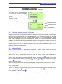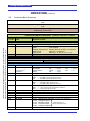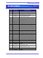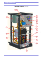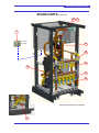
1
Cooling Distribution Unit
INSTALLATION GUIDE
Models: CD150W4
CD150W3
Coolcentric, a Division of Vette Corp
201 Boston Post Road West, Marlborough, MA 01752
Email: [email protected]
Website: www.coolcentric.com
Cooling Distribution Unit
ABOUT THIS DOCUMENT
Using This Document
This document has been designed for viewing as a PDF file and double sided printing
(subject to copyright – see below) for a hard copy. Copies of this document can be
obtained from the address on the front cover.
This is not a controlled document. Distributed copies will not be updated. All
specifications are minimal and subject to change without prior notice as design
improvements occur
Copyright Notice
The confidential information contained in this document is provided solely for use by
the manufacturer’s employees and system owners, and is not to be released to, or
produced for, anyone else. Neither is it to be used for reproduction of this unit or any
of its components. All specifications are nominal and subject to change without prior
notice as design improvements occur.
Disclaimer
The manufacturer shall not be liable for any damages resulting from mis-application
or misuse of its products.
E & OE
GENERAL STATEMENT
Product Standards
Products installed and operated in accordance with instructions, conform to the EMC
directive and essential Health & Safety requirements of the Machinery Directive
91/368/EEC-93/44/EEC & 93/68/EEC. This includes the EMC compatibility directive
89/336/EEC. As standard, units comply with an IP21 rating.
The products are UL listed and certificates will be made available on application to
the address on the front cover.
CDU Installation Guide
Page 2
Cooling Distribution Unit
CONTENTS
Section 1
1.1
1.2
1.3
1.4
1.5
1.6
1.7
1.8
1.9
SAFETY INSTRUCTIONS
General Notice
Installation/Handling
Application
Warranty
Electrical connection
Maintenance
Service parts
Codes of Practice
Waste disposal
Documentation
5
6
6
6
6
6
6
6
6
6
Section 2
2.1
INTRODUCTION
General
7
Section 3
3.1
3.2
3.3
3.4
3.5
3.6
3.7
TECHNICAL DATA
Handling
Pipe Connections
Electrical Connection
Volume Capacity
Noise
Secondary Circuit
Primary Circuit
9
9
9
9
9
9
10
Section 4
4.1
4.2
4.3
4.4
4.5
4.6
INSTALLATION
Mechanical
Electrical
Hydraulic
Heat Transfer Fluids
Flushing
Door Lock Details
13
13
14
15
15
15
Section 5
5.1
5.2
5.3
5.4
5.5
5.6
5.7
5.8
5.9
5.10
5.11
5.12
5.13
COMMISSIONING
Pre-Commissioning Checks
Chilled Water
Controller Setup
Attaching to Mother Board
Display Contrast
Inverter Setup
System Filling
General - Manual Control & Overrides
Manual Control
Overrides
Pump Rotation
Primary Flow Setup
Secondary Flow Balancing Valves
17
17
17
18
18
19
20
21
21
21
22
22
23
Section 6
6.1
6.2
6.3
6.4
6.5
6.6
6.7
OPERATION
Controller Introduction
Controller Menu Summary
Automatic Operation
Acknowledgement of Event Messages
Defer Active Events
Connection of Additional Racks
Control Loop Set-up
25
28
33
36
37
37
38
CDU Installation Guide
Page 3
Cooling Distribution Unit
CONTENTS (continued)
Section 7
7.1
7.2
7.3
7.4
7.5
7.6
PREVENTATIVE MAINTEANCE
General
Every 3 Months
Every 6 Months
Every 12 Months
Filter Flushing
Unit Draining
39
39
39
39
39
40
Section 8
8.1
8.2
TROUBLE SHOOTING
Summary of Event Messages
Temperature Sensor Chart
41
46
Section 9
SPARE PARTS LIST
47
Section 10
10.1
10.2
DIAGRAMS
Wiring Diagram
Pipe Schematic
52
55
Section 11
WARRANTY & SUPPORT
57
CDU Installation Guide
Page 4
Cooling Distribution Unit
SAFETY INSRUCTIONS
Section 1
* * * IMPORTANT NOTICE * * *
ALL PERSONNEL involved in the installation and maintenance of the Process and Ancillary Equipment,
whether directly or indirectly, MUST read this notice and this complete document prior to the
commencement of ANY WORK.
1.
The following information must be READ, FULLY UNDERSTOOD and
ADHERED to AT ALL TIMES.
2.
The SAFETY of YOU and OTHER PERSONS MUST be your main concern.
3.
NEVER carry out a task until you fully understand what you are being asked
to do and how to do it safely.
4.
NEVER carry out a task you feel could be DANGEROUS to you and other
persons.
5.
DO NOT carry out any task that you are not qualified to undertake.
6.
ALWAYS comply with all SAFETY RULES as laid down by the relevant
Authorities.
7.
If you have any questions or concerns over the safety of YOU or OTHER
PERSONS you MUST consult your supervisor within the Company prior to
the commencement of any task.
8.
NEVER start work on a unit or remove any casings, guards, doors or covers
without first SWITCHING OFF and isolating the unit and controllers from the
electrical supply.
9.
Make sure all ROTATING PARTS ARE AT REST before commencement of
any work on the unit.
10. The Safety Policy of the Company on whose premises the unit is installed
should be read and understood by Maintenance Personnel.
* * * ALWAYS THINK SAFETY * * *
Throughout this guide, items of importance are highlighted with the following symbols:
CAUTION: Failure to comply may result in damage to the unit
DANGER: Failure to comply may result in personnel injury
CDU Installation Guide
Page 5
Cooling Distribution Unit
SAFETY INSTRUCTIONS (continued)
General
Temperature
control
equipment
presents
mechanical, electrical, noise or vibration hazards.
Observe all safety, installation, operation and
maintenance instructions.
Installation, servicing and operation of the
equipment can only be carried out by fully trained
and technically competent personnel.
The Cooling Distribution Unit is designed to
minimize mechanical and electrical hazards by
fully restricting access through unit casings,
doors and covers while equipment is operational.
Some installations may require additional
protective features to prevent accidental contact
with components. The CDU manufacturer can
provide advice and make recommendations for
additional protection to suit the application.
All installation work must be completed in
accordance with the safety, installation, operation
and maintenance instructions and the unit
correctly grounded (earthed) before it is operated.
Prior to any maintenance work being carried out,
ensure that:
Equipment is switched OFF
Equipment and controls are disconnected from
the electrical supply.
All rotating parts have come to rest.
If in any doubt as to the correct interpretation of
performing the safety, installation, operation
and maintenance instructions, it is essential that
the CDU manufacturer, their agent or appointed
distributor is consulted for advice and
clarification.
1.1
Installation / Handling
The installation and operation should be
conducted in accordance with local regulations
and accepted codes of good practice.
When moving or lifting the unit, caution must be
observed at all times to ensure the safety of all
personnel. Only appropriate and approved lifting
equipment must be used.
1.2
Application
The unit must be only used in the application for
which it was designed.
The unit is not to be used in a hazardous
environment unless it has been specially
designed and approved for such application.
1.3
1.4
Failure to comply with the manufacturer’s
installation instructions could affect the reliability
and performance of the unit and invalidate the
warranty.
Page 6
Electrical Connection
The unit must be connected to an external
isolator/disconnect if one is not fitted to the unit.
Electrical connections should be carried out in
accordance with national and local regulations.
Never make any connections in the unit circuits
unless the electricity supply has been switched
OFF at the disconnect (isolator).
1.5
Maintenance
For further information, please refer to Section 7 –
Preventative and General Maintenance.
1.6
Service Parts
Service parts must be of the same specification as
those being renewed and should only be obtained
from the CDU manufacturer.
The use of incorrect service parts can affect the
unit operation and reliability and invalidate any
warranty.
1.7
Codes of Practice
It is important that equipment and products which
have been installed and commissioned are
maintained by or under supervision of technical
competent personnel and that all work is carried
out in accordance with good engineering practice
and strict adherence to:
i.
IEE & IEEE Standards
ii.
Codes of good engineering practice
iii.
Local Authorities
iv.
Statutory requirements
v.
Manufacturer’s instructions and
recommendations
vi.
All other relevant information, regulations
and legislation
1.8
Waste disposal
Waste materials must be disposed of in a
professional and responsible manner and in strict
adherence to environmental regulations. For
details, consult local environmental agencies.
1.9
Warranty
CDU Installation Guide
Warranty is subject to the implementation of a
planned service/maintenance agreement - see the
warranty section (Section 11) in this guide or the
sales contract.
Documentation
All documentation must remain with the unit at all
times.
Cooling Distribution Unit
Section 2
INTRODUCTION
2.1
General
This guide describes the basic Installation, Operation and Maintenance of the Cooling Distribution Unit
(CDU) and contains a detailed explanation covering the Technical Specification, Mode of Operation,
description of the alarms that can be generated and the action to be taken at those alarms, a Spare
Parts List and all relevant Schematic Diagrams.
It is assumed that the people involved with the maintenance of this unit are familiar with basic theory
and practice. Consequently only features that are of particular significance to this unit are identified.
The CDU has been designed to provide close controlled cooling water for IT enclosure ‘Rear Door
Heat Exchangers’ (RDHx’s), with a total maximum cooling capacity of 120 or 150kW.
The process side water loop (referred to as the ‘Secondary Circuit’) is a sealed pressurized system with
the heat extracted from the rear door heat exchangers being rejected to a chilled water circuit.
The chilled water can either be part of the Building Services Chilled Water system or supplied from a
dedicated chiller or cooling tower. This chilled water supply loop (referred to as the ‘Primary Circuit’) is
filtered to 300μ (50mesh) using a filtration unit fitted internally to the cabinet.
Features of the CDU include:
1
Control Panel
Controller Display
(user interface)
Plate Heat Exchanger
2
Pump Inverter Drive
Reservoir Tank
Primary Control Valves
(run & standby)
Pump transit bracket
Primary Flow Meter
3 & 4
Level Switch
Secondary Pumps
(run & standby)
Pump Isolation Valves
Lockable Wheels &
Adjustable Plinth
Front View
1 - 4 Location of automatic air vents
CDU Installation Guide
Page 7
Cooling Distribution Unit
INTRODUCTION (continued)
Primary Filter
Primary By-pass Circuit
Primary Isolation Valves
Secondary Return Quick
Release Couplings
Internal
manifold
option
Secondary Supply Quick
Release Couplings
Secondary Hose Clips
Optional Secondary Flow
Control/Balancing Valves
Secondary Pump
Non-Return Valve
Cone seat union couplings
Rear View
(with optional Internal Manifold or
Flex Tails for external Manifold)
CDU Installation Guide
Page 8
Flex Tails
option for
external
manifold
Cooling Distribution Unit
Section 3
TECHNICAL DATA
3.1
Physical
Model:
CD120W4
CD150W4
CD120W3
CD150W3
Cabinet dimensions:
Width
Height
Depth
800mm (31½”)
1825mm (71⅞”)
1085mm (42¾”)
Width
Height
Depth
940mm (37”)
1985mm (78⅛”)
1220mm (48”)
Shipping dimensions:
Weight (inc. manifold):
Dry
Operational
Shipping
3.2
398kg (877½lb)
441.5kg (973½lb)
540kg (1190lb)
407kg (897½lb)
454.5kg (897½lb)
549kg (1210½lb)
398kg (877½lb)
441.5kg (973½lb)
540kg (1190lb)
407kg (897½lb)
454.5kg (897½lb)
549kg (1210½lb)
Pipe Connections
3/4” ISO-B QRC* or 42mm/1½” sweat
Secondary Circuit:
42mm/1½” sweat
Primary Circuit:
*QRC = Quick Release Coupling (self sealing)
3.3
Electrical Connection (see also Section 4.2)
Power Supply 3ph + ground
(earth):
Full Load Amps:
380-480V 50/60Hz
208-230V 50/60Hz
7.3A@400V / 6.7A@480V
11.8@208V
Typ. Power Consumption:
2.6kW
Max. Installed Load
5.6kVA
3.4
CDU Fluid Capacity
Secondary Circuit Volume:
32L (8.45USgall)
33.5L (8.85USgall)
32L (8.45USgall)
33.5L (8.85USgall)
Primary Circuit Volume:
10L (2.64USgall)
11.5L (3.04USgall)
10L (2.64USgall)
11.5L (3.04USgall)
3.5
Noise
Sound power level at 3m/10ft
3.6
Less than 55dBA
Secondary Circuit
Rated Cooling Capacity
120kW
150kW
Pump Capacity
CDU Installation Guide
120kW
240l/m (63.4USgpm)
Page 9
150kW
Cooling Distribution Unit
TECHNICAL DATA (continued)
Pressure available from CDU
0
5
10
15
20
25
Flow (Usgpm)
30
35
40
45
50
55
60
4.5
64
62
60
4.0
58
56
54
52
50
48
46
44
3.0
42
40
Pressure (PSI)
Pressure (Bar)
3.5
38
2.5
36
34
32
30
2.0
28
26
24
1.5
22
0
30
60
U/floor manifold
90
1 RDHx
120
Flow (L/M)
2 RDHx
150
3 RDHx
180
4 RDHx
210
5 RDHx
6 RDHx
240
Series8
The above graph shows the available pressure differential at the secondary supply and return connections
of the CDU. Curves labelled 1 to 6 RDHx are with the internal manifold fitted for 1 to 6 external circuits.
These curves also take into account the pressure drop through the self sealing, quick release couplings.
The curve labelled U/F Manifold is with flexible tails fitted for direct connection to an under floor installed
manifold system (see page 8).
Minimum Approach Temperatures
9
16
14
7
12
6
10
5
8
4
6
3
4
2
Minimum Temperature Differential (o F)
Minimun Temperature Differential (o C)
8
2
1
0
0
20
30
40
120kW CDU (water)
50
60
Percentage of Full Load
120kW CDU (30% glycol)
70
150kW CDU (water)
80
90
150kW CDU (30% glycol)
100
dummy
The above graph shows the minimum temperature differential possible between the Primary chilled water
supply temperature the Secondary set point temperature for the percentage of full CDU rated load. Graph
data based around full primary flow of 230L/M (60.8USgpm) and secondary flow of 240L/M (63.4USgpm).
CDU Installation Guide
Page 10
Cooling Distribution Unit
TECHNICAL DATA (continued)
3.7
Primary Circuit
Primary Flow/Temperature Graph for 120kW CDUs
39
41
43
45
Temperature (o F)
47
49
51
320
300
80
280
75
260
70
65
240
60
220
55
200
50
180
45
160
40
140
35
120
Flow (Usgpm)
Flow (L/M)
Note: To keep pipe
velocities within
limits, it is
recommended that
the brown shaded
area is avoided.
30
100
25
80
20
60
15
40
10
20
5
0
0
4
5
6
7
8
9
Temperature (o C)
1 RDHx (30% glycol)
2 RDHx (water)
3 RDHx (30% glycol)
4 RDHX (water)
5 RDHx (30% glycol)
6 RDHx (water)
1 RDHx (water)
3 RDHx (water)
5 RDHx (water)
10
11
2 RDHx (30% glycol)
4 RDHx (30% glycol)
6 RDHx (30% glycol)
Primary Flow/Temperature Graph for 150kW CDUs
39
41
43
45
Temperature (o F)
47
49
51
220
55
200
50
180
45
160
Flow (L/M)
35
120
30
100
25
80
Flow (USgpm)
40
140
20
60
15
40
10
20
5
0
0
4
5
1 RDHx (water)
3 RDHx (water)
5 RDHx (water)
6
7
8
Temperature (o C)
1 RDHx (30% glycol)
3 RDHx (30% glycol)
5 RDHx (30% glycol)
9
2 RDHx (water)
4 RDHx (water)
6 RDHx (water)
10
11
2 RDHx (30% glycol)
4 RDHx (30% glycol)
6 RDHx (30% glycol)
The graphs above are a guide for the primary water requirements, based on the number of RDHx’s
connected for either plain water or up to 30% ethylene glycol (different % of glycol can be estimated on a
pro-rata basis). The primary water should fall either on the chosen curve or in the area above the curve.
Note: The water flow should not be more than 20% above the recommended value for stable control.
Both the graphs are based around a secondary supply temperature of 18°C (64.4°F) to achieve the full
duty of 20kW per RDHx for the 120kW CDU & 25kW per RDHx for the 150kW CDU.
CDU Installation Guide
Page 11
Cooling Distribution Unit
TECHNICAL DATA (continued)
Primary Circuit Pressure Drops
0
5
10
15
20
Flow (USgpm)
25
30
35
40
45
50
55
60
0.9
13
12
0.8
11
0.7
10
8
0.5
7
6
0.4
5
0.3
Pressure Drop (PSI)
Pressure Drop (Bar)
9
0.6
4
3
0.2
2
0.1
1
0.0
0
0
30
60
120kW CDU (Water)
90
120
Flow (L/M)
120kW CDU (30% Glycol)
150
150kW CDU (Water)
180
210
150kW CDU (30% Glycol)
240
Series5
The graph above shows the maximum pressure drops through the CDU cabinets for both plain water and
water with 30% glycol.
CDU Installation Guide
Page 12
Cooling Distribution Unit
INSTALLATION
4.1
Section 4
Mechanical
Arrival on site: The CDU cabinet is crated and dispatched on a load bearing pallet. On arrival at site
the top and side panels of the crate and the protective bubble wrap should be removed and the
cabinet inspected for any transit damage. If damage is found, it must be reported to the manufacturer
immediately.
The cabinet can be wheeled off the pallet using the crate front as a ramp, or may be removed using a
forklift, which can then be used to transport the unit to its final destination. The cabinet must be kept
within 15° of vertical at all times.
Note: Care should be taken when using a forklift or pallet truck to avoid damaging the drain/sump
point under the middle/front of the unit.
The CDU cabinet is intended for positioning on a smooth and level floor, ideally a raised with at least
300mm (12”) under floor space for hose runs to data rack RDHx’s. For ease of positioning, the unit is
supplied with load bearing wheels. Sufficient space should be allowed at the front and rear of the unit
to fully open the access doors, i.e. in excess of 800mm (31½”). Once in position the corner plinths
supplied loose with the cabinet may be bolted to the underside of the cabinet as shown in Fig.1 and
the unit then raised & levelled with the levelling feet. Plinth covers are also supplied for front and sides
(but not the back to keep area clear for hose runs).
The keys for front & rear doors are supplied in a bag secured to the front door.
4.2
Fig. 1 - View on underside of CDU
form front showing corner plinth
positions (shown in green).
Electrical
A 25mm (1”) cable gland is provided in the underside of the electrical box to accept a 9-17mm (⅜”-⅝”)
diameter power cable. The incoming cable may be routed into the cabinet either via the floor void or
through the cabinet roof panel. Termination point is at the main electrical box disconnect (isolator) and
2
adjacent ground (earth) terminal. Recommended cable size is 4-core 2.5mm (13AWG) minimum.
Upstream protection must be provided by the end user as stipulated on the wiring diagram in the form
of fuses.
Note: The CD120W4 & CD150W4 units are supplied configured for 380-415v 3-phase supply as
standard. If the supply voltage is higher (e.g. 460-480v), then the 400v wire tapping on the control
transformer should be moved to the 460v tapping (see Fig.2) and the thermal overloads reset for 5.7A
(see wiring diagram).
The CD120W3 & CD150W3 units are supplied configured for 208v supply.
In order to maintain the UL listing of the CDU, type RK5 fuse protection must be installed upstream of
this unit, as specified on sht.3 of the CDU wiring diagram (see page 54).
Terminals nos. 1 to 2 and 3 to 4 in the electrical box (supplied linked) can, if required, be connected to
a remote ‘Control Switch’ and building ‘EPO/Fire shut down system’. Breaking either of these circuits
will shut the unit down in an emergency (refer to wiring diagram).
CDU Installation Guide
Page 13
Cooling Distribution Unit
INSTALLATION (continued)
A room temperature & RH sensor is provided with every CDU. As standard this is fitted on the cabinet
front door behind a ventilation grille. If required the sensor can be mounted remotely with the appropriate
cable kit, to be installed on a wall adjacent to the IT enclosures at a height of approx 1.8M (71”).
Fig. 2 – Control Transformer
tappings
Common tapping
(208 - 230v tapping)
380 - 415v tapping
460 - 480v tapping
4.3
Hydraulic
The Primary chilled water hoses can be routed either through the floor void to enter the cabinet from
below along with the process hoses, or from above via the two cut outs in the rear of the cabinet roof
panel. Ball valves are provided for chilled water isolation along with 1½” flexible hose connections for
soldering/brazing to either a 1½” or 42mm copper hard piped installation. The copper pipe should be
suitably supported at installation as close to the stainless braided flexible hose as possible – do not clip to
the cabinet frame.
All primary circuit pipework, hoses and valves should be insulated against condensation.
When the optional internal manifolds are fitted, the secondary circuit hoses should be routed out through
the bottom of the cabinet and through the floor void to each RDHx. Quick release self sealing couplings
are provided on the manifolds for hose connection (see Fig. 3). Crush and kink resistant ¾” bore PVC
hose should be used with a minimum working pressure of 10Bar (145PSI) to connect the CDU cabinet to
each RDHx.
Secondary Circuit RDHx Return
Connections (¾” couplings)
Secondary Circuit RDHx Flow
Connections (¾” couplings)
Primary Chilled Water Connections
(42mm / 1½” copper stubs on flexible tails)
Fig. 3 - Hose Connections (shown with optional internal manifold)
CDU Installation Guide
Page 14
Cooling Distribution Unit
INSTALLATION (continued)
4.4
Heat Transfer Fluids
The CDU cabinet is designed for use with a primary circuit supply of plain water or up to 30%
glycol/water from by a site chilled water ring main or a dedicated chiller - a 30% glycol concentration
will give protection to approx -14°C (7°F).
The secondary circuit should be filled with particulate free deionized water treated with suitable
corrosion inhibitors and preservatives.
For ease of installation and commissioning, premixed treated water designed specifically for the
requirements of closed secondary cooling circuits can be offered as an optional kit. Failure to use
proper water treatment may result in decreased system performance and reliability due to corrosion,
scaling, fouling and microbiological growth.
4.5
Flushing
Where an under floor manifold is installed, provision should be made for flushing connections.
4.6
Door Lock Details
The swing handle locks fitted to both front and rear doors have combination lock as standard, which
can be set as below:
To set a new code
1) Make sure the thumb wheels are in the original factory set position ‘000’.
2) Using a sharp pointed object, push the tip into the small round hole located at
the bottom of the lock.
3) Turn the 3 wheels to your new required combination and release tip.
To reset again, turn combination to your new code then follow steps 2-3.
*NOTE*: Always keep a record of your new code – once lost there is no override facility! The master
key provided will always override the combination lock, but will not reset the combination.
CDU Installation Guide
Page 15
Cooling Distribution Unit
CDU Installation Guide
Page 16
Cooling Distribution Unit
COMMISSIONING
5.1
Section 5
Pre-Commissioning Checks
Check that all items within the unit are secure and undamaged. Pay particular attention to the
pipework.
Inspect all wiring and check that all terminations are tight, especially any ground (earth)
connections.
Ensure that the power supply is correctly connected – see wiring diagram/data plate for rating.
Check the required number of RDHx has been correctly piped up via quick release couplings
to the supply and return manifolds (if fitted) in the cabinet and all hose connections are tight.
Where the optional manifold is installed, fully open the automatic flow balancing valves on the
supply manifold (blue handles) for each RDHx connected.
Check that the primary chilled supply is connected and hose connections are tight.
Check that drain point on the drip tray sump is capped and all drain valves are closed (see
Fig. 9 on page 40).
Check that fuse rating of the power supply is in accordance with the recommendations on the
wiring diagram and motor overload devices are set as per the wiring diagram.
Ensure that cooling water supply does not exceed 10Bar (145PSI) pressure.
Ensure the bleed screws on the four automatic air vents are loose but have not been removed
(see Front View image on page 7 for identification).
Remove pump transit bracket (this is optional and can be left in position if preferred).
5.2
Chilled water
Crack open the inlet and return ball valves fitted at the back of the CDU cabinet (see Fig. 4) to allow the
primary circuit within the cabinet to gently fill from the chilled water supply. The trapped air in this circuit
may be expelled using the manual air bleed valve situated on top of the pipe at the primary entry into the
plate heat exchanger. Once the circuit is filled, the ball valves may be opened fully. Check for leaks.
Primary inlet
ball valve
Primary return
ball valve
Fig. 4 - Primary Connections
5.3
Controller Setup
NOTE: This operation and the following (5.4) will already have been carried out at during the factory test and
will only need to be repeated after a software upgrade.
The power supply may now be switched on using the disconnect (isolator) on the control panel.
Refer to Section 6.1 for a description the screen display and general controller information. Before
actually starting the unit, it will be necessary to setup the controller for the number of RDHx’s attached.
This will then automatically select various software parameters to suit the installation.
To adjust the rack number:
Press keys
&
together for 1 to 2 seconds to enter the next screen from the welcome screen.
Scroll to ‘Logon’ and press OK . Enter the ‘Service’ access code (5699) using
OK
press
.
Scroll up to ‘Setup’ and press OK to display the screen below.
CDU Installation Guide
Page 17
keys and
Cooling Distribution Unit
COMMISSIONING (continued)
Select ‘site setup’ and press OK . Use keys
to set
the number of RDHx attached to the unit, then press OK .
Likewise, set the units to SI or imperial* as required & press
OK , followed by the Daylight Saving hours, Date Format
and Date & Time followed by OK on each occasion. Press
the ESC key to return to welcome screen.
Screen title
Selected screen
ref. number
setup
1-2
attach to unit
site setup
factory defaults
* Note: If ‘units’ are changed during CDU operation, any parameters that have been previously adjusted
will revert to default values.
5.4
Attaching to Mother Board (already carried out during factory test)
If, on power up, the display screen shows ‘Setup’ it means that the display communications with the
controller needs to be re-established. This will need to be done while the system is live. Switch off the
disconnect (isolator), open up the control panel and switch the disconnect (isolator) back on at the
base unit. Press OK, the display screen will show `attach to unit’. Press OK, the display screen will
show ‘Waiting for Service’ msg.
DANGER: This should only be carried out by a qualified electrician.
Next press the controller reset button found adjacent to connector CR4 on the controller mother board.
Reset button beside connector CR4
When the reset button is pressed, the screen will go direct to ‘Site Setup’ where the number of RDHx’s
operating units and the time & date can be set as described in Section 5.3. The screen will then return to
the normal welcome screen.
5.5
Display Contrast
If the display is faint or the text background too dark, the display
contrast should be adjusted. Switch off the disconnect (isolator), open
up the control panel and switch the disconnect (isolator) back on at
the base unit.
DANGER: This should only be carried out by a qualified
electrician.
Adjust the pot on the display PCB shown in the picture, until display
becomes clear.
CDU Installation Guide
Page 18
Cooling Distribution Unit
COMMISSIONING (continued)
5.6
Inverter Setup
The inverter drive has a separate display and
keypad as detailed on the left. The display is set as
standard to show the frequency output to the pump
motors, but repeated pressing of the key with the
circular arrow, will also show also the frequency
reference value and current drawn by the pump.
There are 79 adjustable parameters within the
inverter that have been factory preset to the values
shown in the table below (for full information on
each parameter, refer to the inverter drive guide).
Parameter n01, when set to 0, locks parameters
n02 to n79 (set n01 to 1 for adjustment) –
parameters can only be changed when in the
PRGM mode and the inverter is not operational.
The Run, Stop/Reset keys and the frequency
setting potentiometer are for manual operation only
and have been disabled in the setup.
If the inverter goes to a fault condition the red alarm
LED will blink on and off and an alarm code will
show in the inverter display window (refer to inverter
guide for full details).
Parameter n78 will display a fault code if the inverter goes into a fault condition. This information will be
required by the CDU manufacturer for fault diagnosis.
Parameter
Setting
Parameter
Setting
Parameter
Setting
Parameter
Setting
n01
n02
n03
n04
n05
n06
n07
n08
n09
n10
n11
n12
n13
n14
n15
n16
n17
n18
n19
n20
0
1
2
0
1
1
0
0
60.0
400/208
50.0
1.5
24/12
1.5
24/12
10.0
10.0
10.0
10.0
0
n21
n22
n23
n24
n25
n26
n27
n28
n29
n30
n31
n32
n33
n34
n35
n36
n37
n38
n39
n40
6.0
0.0
0.0
0.0
0.0
0.0
0.0
0.0
6.0
100
0
6.3*/10.8
0
8
0
2
5
3
6
13
n41
n42
n43
n44
n45
n46
n47
n48
n49
n50
n51
n52
n53
n54
n55
n56
n57
n58
n59
n60
100
0
0.10
0
1.00
3
2
0
0.0
0.0
0.0
50
0.5
0.0
0
170
160
0.0
0
160
n61
n62
n63
n64
n65
n66
n67
n68
n69
n70
n71
n72
n73
n74
n75
n76
n77
n78
n79
0.1
0
1.0
3.2
33
0.0
2.0
0
0
0
2
0
10
0
0
RDY
0
--020
Note: Alternative settings for CDU121 & 151 (208-230v operation) are shown in Blue.
* This setting (6.3A) is for 380-415 volts, for 460-480 volts change to 5.7A (refer to wiring diagram).
CDU Installation Guide
Page 19
Cooling Distribution Unit
COMMISSIONING (continued)
5.7
System Filling
Refer to Section 3.4 for system fluid capacities
Operation – for secondary circuit filling
It will not be possible to start the unit with the ‘Unit Start/Stop’ pushbutton until the system has
been manually filled with deionized water (i.e. system start is inhibited by reservoir low level
and low pressure interlocks).
Position container of pre-treated deionized water in front of
the cabinet.
Remove the filling wand from its storage location on the right
hand side of the cabinet and connect to the fill hose (white
quick release coupling), then insert to the bottom of the water
container (see Fig. 5) and press the ‘Fill Pump Enable’
pushbutton.
The fill pumps will then start pumping the contents of the
container into the system at the rate of approx. 2l/m
(0.5USgpm). The pumps may be noisy to start with as they self
prime. See page 21 for how to monitor system pressure
during filling process.
Stop the pumps by pressing the ‘Fill Pump Enable’
pushbutton again before the level drops below the wand
intake, to avoid air being drawn into the system.
If more than one container of treated deionized water is
required (see capacities in Section 3.4), repeat the
procedure above until the fill pumps automatically stop. Fig. 5 - Filling wand
Pumps will stop when inlet pressure ‘PS1’ reaches 0.5Bar
(8PSI). Leave the filling wand in the container - more water
Quick release coupling
will be required during the initial stages of operation as air is
expelled from the system and the main pump inlet pressure
(PS1) drops.
Check for leaks.
Once the unit is commissioned – the filling wand may be
disconnected at the white quick release coupling and the fill
hose then connected to the blue flexible make-up container.
Excess treated water may be used to fill this make-up
container - approx. capacity 2L (0.53USgalls), which will allow
the unit to self-fill while unattended in the event of minor
water loss or when any remaining trapped air is purged out of
the system. The container should be regularly inspected
during service visits and refilled if required, however any fill
pump activity after commissioning is logged as a Check
Water Make-up Level warning, as a reminder for
investigation.
Fig. 6 - Make-up container
Before connecting the blue flexible make-up container, the
air in the container hose should be removed. Fill the
container with water, screw on the fill cap and then squeeze the bag while depressing the
valve on the end of the quick release coupling (see Fig. 6) until air is expelled and hose is full
of water.
NOTE: If there is already pressure in system and air is introduced into the fill pump suction line, then the
fill pumps may not be able to purge this air through the system and may cease to pump. To rectify, switch
unit off and relieve secondary circuit pressure at drain valves(s), then refill system again as above.
Alternatively, leave the unit running while opening a drain valve to relieve pressure, until fill pumps start to
pump.
CDU Installation Guide
Page 20
Cooling Distribution Unit
COMMISSIONING (continued)
The ‘Status’ & ‘Sec. pressure’ screens
can be used to monitor the secondary
circuit pressure during the system filling
process.
See Section 6.1 for further information
on how to access.
status
3-4
room sensor
sec. pressure
prim. pressure
OK
sec. pressure
ps1
ps2
dp
5.8
0.50bar
0.50bar
0.00bar
Pump inlet pressure
Pump outlet pressure
Pump differential
pressure
General - Manual Control & Overrides
In Manual Control mode (accessible when logged on at ‘Service’ level), some automatic control functions
can be manually set without affecting the operation of the rest of the unit. This can be done within the
Manual Control screen (screen ref. 4-4), where the following can be set: Speed for Pump 1 or 2 (inverter
operation), On/Off of Pump 1 or 2 (DOL operation), position of Valve 1 or 2 as a percentage open, On/Off
of fill pumps, On/Off of Warning and Alarm extended events (to check the operation of externally
connected alarm circuits).
In addition, the Override mode (only accessible when logged on at Engineer level), allows the operator to
put the unit into ‘dumb’ mode where all outputs need to be manually set. This can be done within the
Override screen (screen ref. 4-3), where the following can be set: Digital outputs, Speed for Pump 1 or 2,
position of Valve 1 or 2. Note: Once the unit is set to a Manual Override state, the unit will shutdown if
previously running in automatic mode.
5.9
Manual Control
After the initial fill process, it is preferable to run the unit in ‘Manual Control’ with a reduced pump
speed to gently circulate the water - enabling any trapped air to vent out through the auto air vents.
To set the unit for manual operation:
Start the unit, then go to the ‘Logon’ screen and enter the ‘Service’ access code as described in
Section 5.3, scroll down to the ‘Service’ menu title (screen ref. 4) and press OK . Scroll to the ‘Manual
Control’ menu title (screen ref. 4-4) and press OK . Select ‘Secondary Pumps’ (screen ref. 4-4-1) and
then ‘P1 Inverter’ (screen ref 4-4-1-1) and press OK . Use the
or
keys to set the speed to 30%
OK
& press
to accept. (Note: If no keys are pressed within a 15 minute time span, the controller will
revert to automatic mode).
While the main pump is running, the fill pumps may switch on again as air is purged from the system.
5.10
Overrides
The unit can also be run in full Override mode (engineer access required), scroll to ‘Overrides’ screen
(screen ref. 4-3) & press OK . Select ‘Auto/Man mode’ and use the
or
keys to change display
from ‘Automatic’ to ‘Manual’, press OK .
Next select the ‘Digital outputs’ menu title (screen ref. 4-3-2) to display the following screen:
CDU Installation Guide
Page 21
Cooling Distribution Unit
COMMISSIONING (continued)
digital outputs
use arrow keys
1000100000
0 = digital output OFF
1 = digital output ON
(e.g. display above shows Pump P1
selected with inverter drive enabled)
Reading from left to right the digital outputs are:
- Pump P1 contactor (inverter drive)
- Pump P2 contactor (inverter drive)
- Pump P1 contactor (DOL)
- Pump P2 contactor (DOL)
- Inverter drive enable signal
- Inverter drive fault reset
- Level 1 fault alarm
- Level 2 fault alarm
- Fill pump P3
- (not used)
Using the arrow keys, set ‘Pump 1 contactor (inverter drive)’ and ‘Inverter drive enable signal’ to ‘ON’.
Press OK to accept, then ESC to return to previous screen and scroll to ‘AO1 – Inverter’ (screen ref. 43-3). The pump speed can be set here as a percentage – a 30% speed is recommended for an initial
setting. When the OK key is pressed, Pump 1 will ramp up to the set speed.
5.11
Pump Rotation
Once the unit is running, the direction of pump rotation should be checked, the pump should rotate in
an anti-clockwise direction when viewed from above. This can be determined by watching the motor
fan slowing down when the unit is switched OFF. If the direction is clockwise then invert 2 – phases on
the electrical supply connection.
Pump rotation should be checked in all four pump operating modes, i.e. Pump 1 + inverter, Pump 2 +
inverter, Pump 1 DOL & Pump 2 DOL.
DANGER: This should only be carried out by a qualified electrician
5.12
Primary Flow Setup
For best performance the primary water flow rate should be set to an optimum flow. For this purpose, the
number of RDHx’s connected needs to be considered along with the temperature of the incoming water
and level of added glycol. If the water flow is below the necessary requirement, there will be insufficient
cooling and the room temperature will start to rise. If there is too much flow, then the temperature control
could become unstable.
Refer to the graph in Section 3.7 for information on the required flow rate based on incoming water
temperature, the percentage of added glycol and the number of RDHx’s attached to the CDU cabinet.
Primary Flow/Temperature Graph for 120kW CDUs
39
41
43
45
Temperature ( F)
47
49
51
320
300
80
280
75
260
70
65
240
60
55
200
50
180
45
160
40
140
35
120
30
100
25
80
20
60
15
40
10
20
5
0
0
4
5
1 RDHx (water)
3 RDHx (water)
5 RDHx (water)
CDU Installation Guide
6
7
8
9
Temperature ( C)
1 RDHx (30% glycol)
2 RDHx (water)
3 RDHx (30% glycol)
4 RDHX (water)
5 RDHx (30% glycol)
6 RDHx (water)
Page 22
10
2 RDHx (30% glycol)
4 RDHx (30% glycol)
6 RDHx (30% glycol)
11
Flow (Usgpm)
Flow (L/M)
220
Example: If 5 x RDHx’s are
connected to the CDU
cabinet and the temperature
of the incoming primary water
is 7.5°C (45.5°F) with 30%
glycol, then the ‘minimum’
required flow rate would be
155L/M (41USgpm).
Cooling Distribution Unit
COMMISSIONING (continued)
To adjust the primary flow rate:
Set the controller to ‘Manual Control’ as described in Section 5.9 and adjust Valve 1 (screen ref. 4-4-2-1
under ‘Heat Exchanger’) to 100%, this will force Valve 1 to open fully. Next go back to the ‘Status’ mode of
the controller and scroll to the ‘Primary Flow’ screen (screen ref. 3-8) to see the actual primary flow rate.
Use the primary return ball valve (see Fig. 4) to approximately regulate the flow to the required setting.
Then use the primary by-pass valve shown in Fig. 7 to give a finer adjustment of the flow. Set Valve 1
setting back to 0% and set controller mode back to ‘Automatic’ operation.
By-pass Valve Location
Fig. 7 - Primary By-pass Valve
5.13
Secondary Flow Balancing Valves (optional - as part of internal manifold only)
The secondary supply manifold is fitted with an automatic flow control balancing valve for each circuit.
These valves ensure that each circuit always receives the correct flow even if each circuit has a different
pressure drop (e.g. due to longer supply/return hose length). The valves are supplied pre-set to 2400L/H
(40L/M – 10.6USgpm), but are adjustable from 640L/H to 3200L/H (10.7L/M to 53.3L/M – 2.82USgpm to
14.1USgpm).The valves are set as a percentage of full flow, therefore for adjustment of valves to 2400L/H
(10.6USgpm):
Valve setting =
2400 x 100 =
3200
75%
The valves (see item 26 on page 49) are fitted
with a blue plastic cap, which if wound clockwise
will close the valve completely. When the cap is
fully unwound anti-clockwise until ‘loose’, the
valve will control to its pre-setting and this will be
the normal operating position for connected
circuits.
To adjust the valve, first remove the blue plastic
cap, as shown to the right (Note: Only do this
when the cap is fully unscrewed and free turning,
to avoid damage). Raise the grey plastic ring and
turn so that the red mark lines up with the new
setting, then release the ring and replace the blue
plastic cap (Note when replacing the cap, the
arrow markings on the grey section should align
with the flats on the threaded section of the brass
valve body).
CDU Installation Guide
Page 23
Cooling Distribution Unit
CDU Installation Guide
Page 24
Cooling Distribution Unit
Section 6
OPERATION
6.1
Controller Introduction
The CDU controller has been designed to control the supply of cooling water to up to 6 RDHx’s in
unattended IT environments. Cooling water is supplied and controlled to a predefined set point at a
controlled flow rate.
When power is first applied to the unit using the control panel disconnect (isolator) switch, the main
red ‘Power On’ lamp will illuminate, the inverter drive will energize and the graphic display area of the
controller will light up.
The display will show the manufacturer’s logo for a few seconds while the controller goes through an
initiation cycle. During this time the control valves may cycle open/closed – this is normal.
Graphical Display and Keypad
* Graphical
display area
set point
dw o/r
act. temp
Power On
indicator (red)
18.0°C
.0°C
18.4°C
Warning indicator
(flashing amber)
14/07/09 08:30
Alarm indicator
(flashing red)
ESC button
To return to System
(default) Screen in a series
of steps back through menu
structures
Arrow buttons
For menu navigation
and value adjustment
OK button
To enter or accept the
displayed value or command
& to acknowledge alarms
Warning = non-urgent warning alarm (investigate on routine inspection/maintenance)
Alarm = urgent alarm (requiring immediate attention)
See Section 8.1 for explanation of events.
* Screen shots throughout this guide are shown in SI units only.
CDU Installation Guide
Page 25
Cooling Distribution Unit
OPERATION (continued)
After initialization, the display panel will default to the welcome screen below:
Date & time (this will
alternate with the number
of active warnings/alarms
if present)
set point
dw o/r
act. temp
18.0°C
.0°C
18.4°C
07/02/06 08:30
Current secondary circuit
set point
Indicates if Dew Point override or
Dew Point Tracking is active *
Indicates the actual
secondary circuit temperature
* This line will not normally show unless Dew Point
Override or Dew Point Tracking are active. Text will
blink slowly when operational – see Section 6.3
By pressing the display down arrow key
, a second information screen can be displayed as below:
Indicates which pump is running
(1 or 2) & % of full speed **
pump 1
087%
valve 1
050%
man. o/r
off
room 26.0°C 68%rh
** will show ‘on’ if pump is running DOL
Indicates which control valve is
operational (1 or 2) & % open
Indicates if manual override is
active (on or off)
Indicates the room conditions
(temperature & relative humidity)
Note: Pressing either the
or
button for 1 to 2 seconds will toggle the display to read imperial
units (when default is SI), or SI units (when default is imperial). Display will return to default units when
escaped.
Software version
To monitor other ‘status’ functions of the unit:
CDU 1.5
Press both
&
keys together for 1 to 2 seconds
to access the next screen showing a list of menu titles.
Scroll to the ‘Status’ title (screen 3) and press OK to
access.
All the information under the ‘Status’ menu is read only;
therefore a logon password is not required for viewing.
Refer to the table in Section 6.2 to see which functions
can be monitored under the ‘Status’ screen
CDU Installation Guide
Selected screen
ref. number
Page 26
3
logon
status
service
Use up/down keys to
scroll through menu
titles
CDU 1.5
service
time control
parameters
5
Cooling Distribution Unit
OPERATION (continued)
Use the
&
keys to scroll through the options within the ‘Status’ screen - refer to the ‘Controller
Menu Summary’ in Section 6.2 for detail on the viewable information that can be displayed. When a
title is highlighted, press the OK key to view the associated information.
Example 1: By selecting the ‘Heat Exchanger’ title (screen ref. 3-2) and pressing OK , the screen
below will be displayed.
Demand signal to
Valve
Control valve currently
operational (1 or 2)
* System set point
Room temperature
Feedback position
from Valve
1 046%
18.0°C
24.0°C
4.4°C
046%
18.4°C
38%rh
Actual secondary
temperature
Room relative humidity
Calculated dew point
from room conditions
* This figure will show the ‘Fixed’, ‘Dew Point Tracking’ or ‘Ambient Tracking’ set points as a steady
state display. If Dew Point Override is active, then this figure will alternate between the Fixed Set point
and the Override value.
Example 2: By selecting the ‘IO Status’ title (screen ref. 3-12) and pressing
, then selecting
OK
OK
‘Digital I/O’ +
, the screen below will be displayed.
Screen title
0 = digital status OFF
1 = digital status ON
digital i/o
1st line = Digital input status
000000000 1
0000000000
2nd line = Digital output status
Reading from left to right the digital I/O are:
Digital Inputs
- Reservoir tank level switch
- Inverter fault
- Flood tray float switch
- Pump 1 DOL overload
- Pump 2 DOL overload
- Start/Stop push button
- (not used)
- Fill pump push button
- Pulse from primary flow meter
Digital Outputs
- Pump P1 contactor (inverter drive)
- Pump P2 contactor (inverter drive)
- Pump P1 contactor (DOL)
- Pump P2 contactor (DOL)
- Inverter drive enable signal
- Inverter drive fault reset
- Level 1 fault alarm
- Level 2 fault alarm
- Fill pump P3
- (not used)
Note:
The solitary number at the far right of the 1st line (digital inputs), signifies whether 24v supply is present (0 = no 24v)
on the controller motherboard. This should be checked if there is ever a complete control failure.
To return to the welcome screen, repeatedly press the ESC key.
CDU Installation Guide
Page 27
Cooling Distribution Unit
OPERATION (continued)
6.2
Controller Menu Summary
All items shown on this background are available to all personnel with no requirement for an access
code.
All items shown on this background are only available to service engineers only with the correct access
code.
All items shown on this background are only available to factory authorized personnel with the correct
‘Engineering’ access code.
Controller Menu Structure
Screen
/ Level
Title
* Note: If the ‘units’ are changed during CDU operation, any parameters that have
been previously adjusted, will revert to default values in the new chosen ‘units’.
Setup (screen 1)
1-1
Attach to unit
1-2
Site setup
1-3
1-4
Factory defaults
Reset display
(software version 1.5 shown)
Options & (Info)
Waiting for service msg. (press button on mother board to attach)
No. of RDHx
1 to 6 (set as required)
Units*
SI or Imperial
Daylight Saving Hours Europe, Manual, No DST or N. America
Date Format
dd/mm/yy or mm/dd/yy
Date & time
dd/mm/yy hh:mm:ss (24 hour clock)
Reset parameters to defaults
(Clear screen buffer)
Logon (screen 2)
service code – ‘5699’
engineering code – on request from manufacturer
Status (screen 3)
- read only information
3-1
Mode
Standby / Online / Fault / Shutdown / Manual
3-2
Heat exchanger
Valve no
-O/P
--- %
Act
--- %
Secondary
SP
--.- °C(°F)
Act
--.- °C(°F)
(see page 27 for
Room sensor
Temp --.- °C(°F)
RH
--.- %
explanation)
DP o/r
DP
--.- °C(°F)
3-3
Room sensor
--.- (temperature) and --.- (relative humidity)
3-4
Sec. pressure
PS1 --.-- Bar (PSI) (pump suction pressure)
PS2 --.-- Bar (PSI) (pump discharge pressure)
DP
--.-- Bar (PSI) (pump differential pressure)
3-5
Prim. Pressure
PS3 --.-- Bar (PSI) (filter inlet pressure)
PS4 --.-- Bar (PSI) (filter outlet pressure)
DP
--.-- Bar (PSI) (filter differential pressure)
3-6
Sec. Temp
T2a --.- °C(°F) (water supply temperature to RDHx’s)
T2b --.- °C(°F) (water supply temperature to RDHx’s)
Ave --.- °C(°F) (average T2a & T2b)
3-7
Prim. Temp
--.- °C(°F) (incoming chilled water temperature)
3-8
Prim. Flow
--- L/M (USgpm) (chilled water flow – not accurate below 20L/M (5USgpm))
Hours (total run time in hours of pumps 1 & 2)
3-9
Pump Runtimes
Hours (total run time in hours of valve 1 - at 25,50,75 & 100% positions)
3-10
Valve 1 Runtime
Hours (total run time in hours of valve 2 - at 25,50,75 & 100% positions)
3-11
Valve 2 Runtime
3-12
IO status
3-12-1 Digital Inputs & Outputs (see page 27 for explanation)
3-12-2 Analogue Inputs
(Raw input data - for
3-12-3 Resistive Inputs
factory information only)
3-12-4 Universal Inputs
3-12-5 Analogue Outputs
(Raw data for factory information only)
3-13
Reset info
CDU Installation Guide
Page 28
Cooling Distribution Unit
OPERATION (continued)
Title
Service (screen 4)
4-1
Force pump c/o
4-2
Force valve c/o
4-3
Overrides
4-3-1
Auto/man mode
4-3-2
Digital outputs
4-3-3
AO1 – inverter
4-3-4
AO2 – valve 1
4-3-5
AO3 – valve 2
4-4
Manual Control
4-4-1
Secondary
pumps
4-4-2
4-4-3
4-4-4
4-4-5
4-5
4-6
4-6-1
4-6-2
4-6-3
4-6-4
4-6-5
4-7
4-7-1
4-7-2
Heat exchanger
Fill pump P3
Warning fault
Alarm fault
Suppress Events
Reset Run Hours
Pump P1
Pump P2
Valve V1
Valve V2
All
Defer Active Event(s)
Period
Initiate
Time control (screen 5)
5-1
Date & time
5-2
Date format
5-3
Daylight saving
5-3-1
Adjustment
5-3-2
Manual dates
Parameters (screen 6)
6-1
Reservoir
6-1-1
Fill pressure
6-1-2
Fill pump run
6-1-3
6-2
6-2-1
6-2-2
Float switch delay
Secondary pumps
No of RDHx
DP setpoints
(pump differential
pressure set points for
pump speed control
loop)
6-2-3
6-2-4
DP loop refresh
Pump DP hys
CDU Installation Guide
Options & (Info)
(change pump from 1 to 2 or 2 back to 1 – OK to initialise)
(change valve from 1 to 2 or 2 back to 1 – OK to initialise)
(no automatic function - for full manual control of all functions)
Automatic / Manual (set unit to manual or automatic operation)
0000000000 (manually set digital output status – see Section 5.8)
0 to 100 % (manually set pump speed)
0 to 100 % (manually set valve 1 position)
0 to 100 % (manually set valve 2 position)
(for manual control of some functions while still running in automatic mode)
4-4-1-1 P1 inverter (set pump speed)
4-4-1-2 P2 inverter (set pump speed)
4-4-1-3 P1 DOL (switch to Manual for ON)
4-4-1-4 P2 DOL (switch to Manual for ON)
4-4-2-1 Valve 1 (set valve position)
4-4-2-2 Valve 2 (set valve position)
Automatic/Manual (switch to Manual for ON)
Automatic/Manual (simulate fault on customer warning relay)
Automatic/Manual (simulate fault on customer alarm relay)
(resets alarm delay timer (scr.6-7) to stop nuisance alarms breaking through
screens during manual overrides – OK to initialise)
(set pump 1 run hours to zero – OK to initialise)
(set pump 2 run hours to zero – OK to initialise)
(set valve 1 run hours to zero – OK to initialise)
(set valve 2 run hours to zero – OK to initialise)
(set all pump & valve run hours to zero – OK to initialise)
Default 24 Hours [adj. 24, 48. 72 hrs] (set alarm defer period)
(OK to initialise)
dd/mm/yy hh:mm:ss (set date & time - 24 hour clock)
dd/mm/yy or mm/dd/yy
Europe, Manual, No DST or N. America
--/-- --/-SI U N IT S
Default 0.5 Bar [adj. 0.5 to 1 bar] (shut off threshold for fill pump)
Default 3 mins [adj. 1 to 15 mins] (run time for float switch to make or fill
pressure to be achieved, prior to alarm)
Default 4 secs [adj. 1 to 30 secs] (reservoir float switch de-bounce time)
Default
6-2-2-1
6-2-2-2
6-2-2-3
6-2-2-4
6-2-2-5
6-2-2-6
Default
Default
1 [adj. 1 to 6]
Sys diff 1 RDHx – Default 2.1 Bar [adj. 0.5 to 4 bar]
Sys diff 2 RDHx – Default 2.3 Bar [adj. 0.5 to 4 bar]
Sys diff 3 RDHx – Default 2.5 Bar [adj. 0.5 to 4 bar]
Sys diff 4 RDHx – Default 2.7 Bar [adj. 0.5 to 4 bar]
Sys diff 5 RDHx – Default 2.9 Bar [adj. 0.5 to 4 bar]
Sys diff 6 RDHx – Default 3.1 Bar [adj. 0.5 to 4 bar]
10 [adj. 5 to 120 secs] (scan period for pump speed control loop)
0.5 Bar [adj. 0.1 to 3 bar] (threshold for pump low flow alarm)
Page 29
* * * SI UNITS * * *
Screen
/ Level
Cooling Distribution Unit
OPERATION (continued)
Screen
/ Level
Title
Options & (Info)
6-2-5
6-2-6
6-2-7
6-2-8
Pump DP delay
DOL DP set point
PV c/o interval
PV c/o time
Default 80 secs [adj. 1 to 300 secs] (time delay prior to pump low flow alarm)
Default 2 Bar [adj. 1 to 5 bar] (pump differential pressure set point when DOL)
Default 7 days [adj. 1 to 30 days] (pump/valve duty sharing period)
Default 03:00 hrs [adj. 00:00 to 23:59 hrs] (time of day for pump/valve duty
6-2-9
6-2-10
6-2-11
6-2-12
Pump c/o delay
Max ctrl.press
Min pump speed
Over pressure
6-2-13
Inverter startup
* * * SI UNITS * * *
6-2-14
6-3
6-3-1
6-3-2
Fault attempts
Heat exchanger
Set point
Valve runtime
6-3-3
Control mode
6-3-4
6-3-5
Dew point offset
CV loop refresh
6-3-6
Demand/act error
6-3-7
6-3-8
Valve check int
Loop settings
6-3-9
6-3-10
6-3-11
6-3-12
6-4
6-4-1
6-4-2
6-4-3
6-4-4
6-4-5
6-4-6
6-4-7
6-5
6-5-1
6-5-2
6-5-3
6-5-4
6-5-5
6-5-6
6-5-7
6-5-8
6-5-9
6-6
6-7
6-8
6-8-1
Sec low temp
Sec high temp
Sec temp hys
Sec high temp
DW
Primary
Prim flow delay
Prim low temp
Prim high temp
Prim temp hys
Prim filter dirty
Prim filter hys
Prim filter delay
Offsets
Prim temp T1
Sec. temp T2a
Sec. temp T2b
Room. temp T3
Room RH
Pump PS1
Pump PS2
Prim filter PS3
Prim filter PS4
Manual period
Event delay
Flood operation
Flood op. switch
CDU Installation Guide
sharing change over)
Default 5 secs [adj. 1 to 10 secs] (dead time between pump change over)
Default 4 Bar [adj. 1 to 8 bar] (max pump speed control loop pressure)
Default 10 % [adj. 0 to 50 %] (set minimum pump speed)
6-2-12-1 Set point – Default 7.5 Bar [adj. 2 to 7.5 Bar]
6-2-12-2 Action – Default Alarm [adj. alarm only / shutdown]
6-2-13-1 Speed – Default 0 % [adj. 0 to 100 %] (initial start speed)
6-2-13-2 Period – Default 0 secs [adj. 0 to 30 secs] (delay prior to pump
speed DP loop becoming operational)
Default 1 [adj. 0 to 5] (no. of inverter restarts before fault recognition)
Default 18.0 °C [adj. 10 to 25 °C] (water supply temperature to racks)
Default 40 secs [adj. 10 to 180 secs] (valve motor run time for control loop)
Default Fixed SP + Dew Point override [adj. Fixed SP, Fixed SP + DW
O/R, DW tracking]
Default 2 °C [adj. 1 to 3 °C] (maintains set point threshold above dew point)
Default 5 secs [adj. 1 to 30 secs] (scan period for valve position control)
Default 10 % [adj. 0 to 50 %] (difference between demand & actual valve
position prior to alarm / change over)
Default 15 min [adj. 1 to 120 mins] (scan period for valve position monitoring)
6-3-8-1 Prop band – Default 17.0°C [adj. 1.0 to 25 °C]
6-3-8-2 Integral reset – Default 400 secs [adj. 0 to 999 secs]
Default 2.0 °C [adj. 1 to 10 °C] (temp. alarm threshold below set point)
Default 2.0 °C [adj. 1 to 10 °C] (temp. alarm threshold above set point)
Default 1.0 °C [adj. 0.5 to 5 °C] (low/high alarm reset threshold)
Default 20 °C [adj. 15 to 25 °C] (high alarm threshold when dew point
tracking)
Default
Default
Default
Default
Default
Default
Default
5 mins [adj. 1 to 30 mins] (time delay prior to alarm)
4 °C [adj. 2 to 10 °C] (low temp. alarm threshold)
11 °C [adj. 6 to 25 °C] (high temp. alarm threshold)
1 °C [adj. 0.5 to 5 °C] (low/high temp. alarm reset threshold)
0.6 Bar [adj. 0.2 to 1 Bar] (diff. pressure alarm threshold)
0.2 Bar [adj. 0.1 to 0.5 Bar] (alarm reset threshold)
60 secs [adj. 5 to 7200 secs] (time delay prior to alarm)
Default
Default
Default
Default
Default
Default
Default
Default
Default
Default
Default
0 °C [adj. +/-10 °C] (sensor calibration)
0 °C [adj. +/-10 °C] (sensor calibration)
0 °C [adj. +/-10 °C] (sensor calibration)
0 °C [adj. +/-10 °C] (sensor calibration)
0 % [adj. +/-10 %] (sensor calibration)
0 Bar [adj. +/-1 Bar] (sensor calibration)
0 Bar [adj. +/-1 Bar] (sensor calibration)
0 Bar [adj. +/-1 Bar] (sensor calibration)
0 Bar [adj. +/-1 Bar] (sensor calibration)
15 min [adj. 1 to 120 mins] (time delay before system reverts to auto)
20 min [adj. 1 to 120 mins] (alarm suppression on start up)
Default Alarm [adj. alarm only / shutdown] (unit flood tray sensor operation)
Page 30
Cooling Distribution Unit
OPERATION (continued)
6-8-2
6-8-3
6-8-4
6-9
Title
Options & (Info)
Flood op. u/f
Threshold u/f
Flood delay u/f
Event relays
Default Alarm [adj. alarm only / shutdown] (under floor sensor tape operation)
Default 143 [adj. 75 to 250] (u/f sensor sensitivity)
Default 10 secs [adj. 5 to 60 secs] (u/f sensor alarm/shutdown delay)
Default N/O [adj. normally closed, normally open] (relay operation mode)
Parameters (screen 6)
6-1
Reservoir
6-1-1
Fill pressure
6-1-2
Fill pump run
6-1-3
6-2
6-2-1
6-2-2
Float switch delay
Secondary pumps
No of RDHx
DP setpoints
(pump differential
pressure set points for
pump speed control
loop)
6-2-3
6-2-4
6-2-5
6-2-6
6-2-7
6-2-8
DP loop refresh
Pump DP hys
Pump DP delay
DOL DP set point
PV c/o interval
PV c/o time
6-2-9
6-2-10
6-2-11
6-2-12
Pump c/o delay
Max ctrl.press
Min pump speed
Over pressure
6-2-13
Inverter startup
6-2-14
6-3
6-3-1
6-3-2
Fault attempts
Heat exchanger
Set point
Valve runtime
6-3-3
Control mode
6-3-4
6-3-5
6-3-6
Dew point offset
CV loop refresh
Demand/act error
6-3-7
6-3-8
Valve check int
Loop settings
6-3-9
6-3-10
6-3-11
6-3-12
Sec low temp
Sec high temp
Sec temp hys
Sec high temp
DW
Primary
Prim flow delay
6-4
6-4-1
CDU Installation Guide
IM PER I A L U N IT S
Default 8 PSI [adj. 8 to 15 psi] (shut off threshold for fill pump)
Default 3 mins [adj. 1 to 15 mins] (run time for float switch to make or fill
pressure to be achieved, prior to alarm)
Default 4 secs [adj. 1 to 30 secs] (reservoir float switch de-bounce time)
Default 1 [adj. 1 to 6]
6-2-2-1 Sys diff 1 RDHx – Default 30 PSI [adj. 8 to 60 psi]
6-2-2-2 Sys diff 2 RDHx – Default 33 PSI [adj. 8 to 60 psi]
6-2-2-3 Sys diff 3 RDHx – Default 36 PSI [adj. 8 to 60 psi]
6-2-2-4 Sys diff 4 RDHx – Default 39 PSI [adj. 8 to 60 psi]
6-2-2-5 Sys diff 5 RDHx – Default 42 PSI [adj. 8 to 60 psi]
6-2-2-6 Sys diff 6 RDHx – Default 45 PSI [adj. 8 to 60 psi]
Default 10 [adj. 5 to 120 secs] (scan period for pump speed control loop)
Default 8 PSI [adj. 2 to 45 psi] (threshold for pump low flow alarm)
Default 80 secs [adj. 1 to 300 secs] (time delay prior to pump low flow alarm)
Default 30 PSI [adj. 15 to 70 psi] (pump diff. press. set point when DOL)
Default 7 days [adj. 1 to 30 days] (pump/valve duty sharing period)
Default 03:00 hrs [adj. 00:00 to 23:59 hrs] (time of day for pump/valve duty
sharing change over)
Default 5 secs [adj. 1 to 10 secs] (dead time between pump change over)
Default 60 PSI [adj. 15 to 115 psi] (max pump speed control loop pressure)
Default 10 % [adj. 0 to 50 %] (set minimum pump speed)
6-2-12-1 Set point – Default 105 PSI [adj. 30 to 105 psi]
6-2-12-2 Action – Default Alarm [adj. alarm only / shutdown]
6-2-13-1 Speed – Default 0 % [adj. 0 to 100 %]
6-2-13-2 Period – Default 0 secs [adj. 0 to 30 secs]
Default 1 [adj. 0 to 5] (no. of inverter restarts before fault recognition)
Default 65 °F [adj. 50 to 75 °F] (water supply temperature to racks)
Default 40 secs [adj. 10 to 180 secs] (valve motor run time for control loop)
Default Fixed SP + Dew Point override [adj. Fixed SP, Fixed SP + DW
O/R, DW tracking]
Default 4 °F [adj. 2 to 6 °F] (maintains set point threshold above dew point)
Default 5 secs [adj. 1 to 30 secs] (scan period for valve position control)
Default 10 % [adj. 0 to 50 %] (difference between demand & actual valve
position prior to alarm / change over)
Default 15 min [adj. 1 to 120 mins] (scan period for valve position monitoring)
6-3-8-1 Prop band – Default 31°F [adj. 2 to 75 °F]
6-3-8-2 Integral reset – Default 400 secs [adj. 0 to 999 secs]
Default 4 °F [adj. 2 to 18 °F] (temp. alarm threshold below set point)
Default 4 °F [adj. 2 to 18 °F] (temp. alarm threshold above set point)
Default 2 °F [adj. 1 to 9 °C] (low/high alarm reset threshold)
Default 70 °F [adj. 60 to 75 °F] (high alarm threshold when dew point tracking)
Default 5 mins [adj. 1 to 30 mins] (time delay prior to alarm)
Page 31
* * * IMPERIAL UNITS * * *
Screen
/ Level
Cooling Distribution Unit
OPERATION (continued)
* * * IMPERIAL UNITS * * *
Screen
/ Level
6-4-2
6-4-3
6-4-4
6-4-5
6-4-6
6-4-7
6-5
6-5-1
6-5-2
6-5-3
6-5-4
6-5-5
6-5-6
6-5-7
6-5-8
6-5-9
6-6
6-7
6-8
6-8-1
6-8-2
6-8-3
6-8-4
6-9
Title
Prim low temp
Prim high temp
Prim temp hys
Prim filter dirty
Prim filter hys
Prim filter delay
Offsets
Prim temp T1
Sec. temp T2a
Sec. temp T2b
Room. temp T3
Room RH
Pump PS1
Pump PS2
Prim filter PS3
Prim filter PS4
Manual period
Event delay
Flood operation
Flood op. switch
Flood op. u/f
Threshold u/f
Flood delay u/f
Event relays
Event Log (screen 7)
7-1
View active
7-2
Clear active
7-3
View log
7-4
Clear log
7-5
Diagnostics
Connectivity (screen 8)
8-1
N/W address
8-2
CDUA-133
8-2-1
Attach
8-2-2
Remove
8-3
CDUA-105-X
8-3-1
Web server
8-3-2
8-4
Modbus
Status
Options & (Info)
Default
Default
Default
Default
Default
Default
40 °F [adj. 35 to 50 °F] (low temp. alarm threshold)
52 °F [adj. 45 to 75 °F] (high temp. alarm threshold)
2 °F [adj. 1 to 9 °F] (low/high temp. alarm reset threshold)
9 PSI [adj. 3 to 15 psi] (diff. pressure alarm threshold)
3 PSI [adj. 1 to 8 psi] (alarm reset threshold)
60 secs [adj. 5 to 7200 secs] (time delay prior to alarm)
Default
Default
Default
Default
Default
Default
Default
Default
Default
Default
Default
0 °F [adj. +/-15 °F] (sensor calibration)
0 °F [adj. +/-15 °F] (sensor calibration)
0 °F [adj. +/-15 °F] (sensor calibration)
0 °F [adj. +/-15 °F] (sensor calibration)
0 % [adj. +/-10 %] (sensor calibration)
0 PSI [adj. +/-15 psi] (sensor calibration)
0 PSI [adj. +/-15 psi] (sensor calibration)
0 PSI [adj. +/-15 psi] (sensor calibration)
0 PSI [adj. +/-15 psi] (sensor calibration)
15 min [adj. 1 to 120 mins] (time delay before system reverts to auto)
20 min [adj. 1 to 120 mins] (event suppression on start up)
Default Alarm [adj. alarm only / shutdown] (unit flood tray sensor operation)
Default Alarm [adj. alarm only / shutdown] (under floor sensor tape operation)
Default 143 [adj. 75 to 250] (u/f sensor sensitivity)
Default 10 secs [adj. 5 to 60 secs] (u/f sensor alarm/shutdown delay)
Default N/O [adj. normally closed, normally open] (relay operation mode)
(view all currently active warnings & alarms)
(clear all active warnings & alarms)
(view last 30 logged warnings/alarms with generated date/ time)
(clear all logged warnings/alarms)
(Raw data - for factory information only)
(network address)
(new style Web server with Modbus gateway)
(attach Web server)
(remove Web server)
(older style Web server / Modbus gateway **)
8-3-1-1
8-3-1-2
8-3-2-1
8-3-2-2
8-3-2-3
8-3-2-4
8-3-2-5
Attach (attach Web server)
Remove (remove Web server)
Attach (attach modbus)
Remove (remove modbus)
Status
Address - Default 1 [adj. 1 to 247] (modbus address)
Protocol - Default rtu [adj. rtu or ASCII] (modbus protocol)
(web server / modbus gateway operational diagnostics)
** CDUA-105-1 Web server only
CDUA-105-2 Modbus gateway only
CDUA-105-3 Web server with Modbus gateway
CDU Installation Guide
Page 32
Cooling Distribution Unit
OPERATION (continued)
6.3
Automatic operation
After commissioning, the unit will be ready to run in automatic mode – press the Start/Stop button on
the control panel to start the unit.
Secondary Circuit Operation
On receiving a start signal, the green Start/Stop push button will illuminate and providing the
reservoir level switch is made, Pump 1 will start to increase in speed – the pump speed as a
percentage of maximum can be read from the second welcome screen (see Section 6.1). The
inverter display will also show the actual ‘frequency’ output to the pump motor.
- If the level switch is not made, signifying insufficient water, then neither main pump
will be allowed to run.
- In this event, the fill pumps will automatically initialise in an attempt to refill the system
and the green ‘Fill Pump Enable’ lamp will illuminate. If after a period of 3 minutes the
level switch has still not made, then the fill pumps will stop and an ‘Insufficient Water
Level’ alarm will be generated. It will not be possible to restart the unit until the alarm
has been manually cleared.
The system pressure at the pump suction (PS1) is continuously monitored (see controller
screen 3-4) to ensure that the system is always pressurized.
- A low system pressure of 0.3Bar (5PSI) or less at PS1 will not stop the main pumps
from running, but will again initialise the fill pumps (after a 10 second delay) to raise
the PS1 pressure to 0.5Bar (8PSI), at which point the fill pumps will stop. At the same
time a ‘Check Water Make-up Level’ warning will be generated. As previously, if the fill
pumps run for more than 3 minutes and the PS1 pressure has still not reached 0.5 Bar
(8PSI), then the fill pumps will stop and a ‘Water Make-up Empty’ warning will be
generated. This is a latched warning and will need to be manually cleared, but will not
stop the unit operating.
The differential pressure across the operational pump is monitored with sensors PS1 & PS2
(see controller screen 3-4) and on start up, the pump speed is increased in stages via a
control loop until the differential pressure matches a predefined setting in the software, based
on the number of RDHx’s set during the commissioning stage. The pump pressure control
loop has a scan default time of 10 seconds to avoid control oscillation.
- If Pump 1 fails to reach within 0.5Bar (8PSI) of this differential pressure in a set time
period (default 80secs), then it is assumed that there is a pump flow fault – Pump 1
will ramp down to a stop and Pump 2 will be initialised after a 5 second interval. At the
same time, a ‘Pump 1 Inverter Low Flow’ alarm will be generated.
- If Pump 2 also fails to reach the differential pressure within the time limit, then this
pump will also ramp down to a stop and Pump 1 will be started direct on line (DOL). At
the same time, a ‘Pump 2 Inverter Low Flow’ alarm will be generated.
- If Pump 1 DOL fails to reach an alternative differential pressure set for DOL operation
(default 2Bar (30PSI)), then it too will stop and Pump 2 will be started DOL. At the
same time, a ‘Pump 1 DOL Low Flow’ alarm will be generated.
- In the event that Pump 2 DOL also fails to reach pressure, a ‘Pump 2 DOL Low Flow’
alarm will be generated. The unit will then continue to operate with Pump 2 DOL until
alarms are manually cleared and faults investigated.
During normal healthy running, the pumps will operate on a duty sharing cycle, i.e. every 7
days (default) the operational pump will ramp down to a stop and the standby pump will then
start after a 5 second delay to continue operating for the next 7 days etc. Changeover default
time is set at 03:00 in the morning.
The secondary water temperature is monitored at the reservoir outlet. Two temperature
sensors are positioned here to give component redundancy. The controller will take an
average between the two readings as its input value. If the difference between the two
sensors exceeds 1.0°C (2°F), then a ‘Secondary Temp Diff Error’ alarm will be raised (after a 2
minute delay).
CDU Installation Guide
Page 33
Cooling Distribution Unit
OPERATION (continued)
If either sensor goes open circuit, then a ‘Sec Temp Out of Range’ alarm will be raised and the
controller will read the remaining working sensor only.
The secondary temperature should correspond to the desired set point temperature – default
fixed set point is 18°C (65°F) as displayed on the welcome screen and is used by the control
loop to regulate the primary water control valve position to achieve and maintain the set point.
The control valve position can be monitored on the second welcome screen (see Section 6-1)
or screen 3-2 under the Status title. High and low temperature warnings are set at a default
value of 2°C (4°F) either side of set point (floating with set point) when either ‘Fixed SP’ or
‘Fixed SP + Dew Point override’ control is selected from screen 6-3-3, with a default
hysteresis of 1°C (2°F).
- If the secondary temperature deviates by more than 2°C (4°F) above set point for 2
minutes or more, a ‘Secondary Water Temp High’ warning will be generated. This
alarm will remain present until the temperature falls below the hysteresis value.
- If the secondary temperature deviates by more than 2°C (4°F) below set point for 2
minutes or more, a ‘Secondary Water Temp Low’ warning will be generated. This
alarm will remain present until the temperature rises above the hysteresis value.
- The high and low temperature warnings are ignored for a period of 20 minutes
(default) on start up to allow the system time to settle without generating nuisance
alarms.
In ‘Fixed Sp + Dew Point override’ control mode, the set point can be overridden by a Dew
Point condition – i.e. where there is a risk of condensation occurring at the RDHx’s.
- Dew Point Override (flashing ‘dw o/r --.-°C (°F)’ on welcome screen display when
activated) – Room temperature and relative humidity are constantly monitored by
remote sensor and used by the controller to calculate the anticipated dew point within
the room. If there is a risk of condensation within the RDHx’s, the controller will
override the set point to a default value of 2°C (4°F) above dew point. The Dew Point
override will then show the new set point value as a flashing display on the second
line of the welcome screen (& also on the Status screen 3-2, which will alternate
between fixed set point & override set point).
Alternatively, if ‘Dew Point Tracking’ is the chosen control mode, then the set point will
continually re-adjust to maintain the supply temperature at a default of 2°C (4°F) above the
current dew point.
- Dew Point Tracking (flashing ‘dw tracking’ on display) – Room temperature and
relative humidity are constantly monitored by remote sensor and used by the
controller to calculate the anticipated dew point within the room. The controller will
then calculate a set point to maintain the water temperature at a default setting of 2°C
(4°F) above this value. The welcome screen will then show the new set point value
with ‘DW Tracking’ as a flashing display on the second line (new set point also visible
on the Status screen 3-2).
Note: Although the controller will display the new Dew Point Tracking set point, this may not always be
achievable as it will often fall outside the cooling capacity of the unit, i.e. if the dew point was 7° C
(44°F), then the controller would re-adjust the set point to 9°C (48°F), however, the plate heat
exchanger is sized for a minimum temperature differential between primary water inlet and secondary
outlet temperatures of 8°C (14.5°F). Therefore, if the primary water temperature was 10°C (50°F), then
a secondary set point of 9°C (48°F) would be unachievable and the ‘actual’ temperature displayed
would be unlikely to fall below 18°C (64.5°F). For this reason it is not possible to operate a Secondary
High/Low temperature warning as with the ‘Fixed SP’ or ‘Fixed SP + Dew Point override’ control
modes that floats with the set point, as the unit could be constantly in warning condition. In this
instance, a fixed Secondary Water Temp High warning is set at a default value of 20°C (70°F) and the
Secondary Water Temp Low warning is only enabled when the temperature drops to or below the dew
point for a period of 3 minutes or more.
CDU Installation Guide
Page 34
Cooling Distribution Unit
OPERATION (continued)
Primary Circuit Operation
The primary water temperature is monitored at the inlet to the CDU cabinet. The cooling
performance of the CDU cabinet has been calculated on a water temperature between 5 and
10°C (41 and 50°F).
- If the primary temperature rises to 11°C (52°F), a ‘Primary Water Temp High’ warning
will be generated. This warning will remain present until the temperature falls below
the default 1°C (2°F) hysteresis value.
- If the primary temperature falls to 4°C (40°F), a ‘Primary Water Temp Low’ warning will
be generated. This warning will remain present until the temperature rises above the
default 1°C (2°F) hysteresis value.
- The high and low temperature warnings are ignored for a 20 minute period (default)
on start up to allow the system time to settle without generating nuisance alarms.
The temperature PI control loop will be operational from when the Start/Stop button is pressed
and the pump has ramped up to speed. If the secondary circuit temperature starts to rise
above the set point, then control Valve 1 will start to open to allow more primary cooling water
through the heat exchanger. The control valve will modulate from 0% (closed) to 100% (fully
open) - the valve position can be monitored on the second welcome screen or Status screen
3-2. The demand signal to the valve is compared to a position feedback signal every 15
minutes (default) to check the healthy operation of the valve.
- If the feedback signal is more than 10% different from the demand signal (allowing for
the drive time of the actuator to respond to load changes), then a ‘Valve 1 Fault’
warning will be generated, Valve 1 will be driven closed and the demand signal
transferred to Valve 2.
- Similarly, with Valve 2 if the feedback signal is more than 10% different from the
demand signal (allowing for the drive time of the actuator to respond to load changes),
then a ‘Valve 2 Fault’ warning will be generated, Valve 2 will be driven closed and the
demand signal transferred to Valve 1.
- If both Valve 1 & Valve 2 are in fault condition, then the warning status of each will be
elevated to alarm level (operation will revert back to the default valve and will stay on
that valve until fault is rectified).
During normal healthy running, the control valves will operate on the same duty sharing cycle
as the pumps, i.e. every 7 days (default) the operational valve will ramp down to closed and
other valve will then respond to the demand signal to continue operating for the next 7 days
etc. Changeover default time is set at 03:00 in the morning.
Both control valves have a ‘spring return’ function to ensure the valves close in the event of a
power failure.
A 300μ (50mesh) primary water filter is fitted at the chilled water inlet to the plate heat
exchanger. The differential pressure is monitored across this filter with sensors PS3 & PS4
(see controller Status screen ref. 3-5) to predict when the filter requires cleaning/flushing.
- If the differential pressure exceeds 0.6Bar (9PSI), then a ‘Primary Filter Dirty’ warning is
generated. Filter may be flushed while operational as described in Section 7.5.
A flow meter in the primary water return line monitors flowrate. The flow can be read within the
controller Status screen ref. 3-8. Note: The flow meter is in series with the flow control valves
and will therefore only register a flow when either valve is open or partially open.
- A ‘Primary Low Flow’ warning is generated only if the following conditions are met:The Secondary High Temperature warning is active, there is no Primary High
Temperature warning present and the demand to the operational control valve is at
100%.
- A ‘Primary No Flow’ alarm can also be generated when the following conditions are
met:- The Secondary High Temperature warning is active, there is a Primary High
Temperature alarm present and the demand to the operational control valve is at
100%.
- Note: Flows below 20L/M (5USgpm) will not be accurate and may not display at all.
CDU Installation Guide
Page 35
Cooling Distribution Unit
OPERATION (continued)
6.4
Acknowledgement of Event Messages
Event messages will break through onto the welcome screen as and when they occur, as in the example
below. Events are categorised into two levels: ‘Warnings’ and ‘Alarms’.
See Section 8.1 for identification of all event messages.
! warning !
code : w20
valve 1 fault
!! alarm !!
code : a12
pump 1 inverter
low flow
Typical Warning screen
Typical Alarm screen
When an event condition occurs, two things will happen:
The initiated event will break through onto the normal screen, the display will then
alternate between the event message and the normal screen. If more than one event is
present, the display will alternate between scrolling through the events, then back to the
normal screen etc.
The event is automatically logged in the Event Log with the date & time at which it was
generated (see Screen 7-1 to review active events and Screen 7-3 to see the full log
history).
The Event Log keeps a rolling record of the last 30 generated events. When the Log reaches the limit of
30, the next event generated will drop the oldest event out of the log etc.
All event messages can be acknowledged by pressing the OK key once for each event as they break
through. This will stop the alarm(s) from breaking through the normal screen and deposit them in an
‘Active’ list.
After acknowledgement and in order to keep the operator informed that event(s) are still active, the
time and date on the welcome screen will alternate with the number of active events, broken down into
‘Warnings’ and ‘Alarms’ if both are present. Similarly, if the screen is displaying a sub-screen, then the
top right hand corner of the display will alternate between the screen identification number and the
number of active events.
All active / acknowledged events can be reviewed by going to Screen 7-1.
Some events will ‘self clear’ if the event is a transient one (e.g. a temperature hits a warning threshold
then comes back to a healthy condition) or when the fault has been rectified (e.g. a faulty sensor has
been replaced). The self clearing alarms are identified in Section 8.1.
CDU 1.5
3 Alarms
Text in top right hand corner of screen
will alternate from displaying the Screen
identification number, to number of
active Events when present (i.e. number
of Active Warnings and/or number of
Active Alarms).
logon
status
service
All events that self clear will continue to remain present the Event Log however, until forced out by the
over 30 event rule, or when the Event Log is manually cleared by an engineer after logging on under
the ‘Engineering’ access code.
Events that do not self clear, as identified in Section 8.1 and require operator intervention for
rectification (e.g. to reset a tripped overload) will need to be manually cleared from the ‘Active’ list by
an engineer after logging on under the ‘Engineering’ access code.
CDU Installation Guide
Page 36
Cooling Distribution Unit
OPERATION (continued)
6.5
Defer Active Event(s)
When a Warning or Alarm event is generated, volt free relay contacts are also activated within the
controller to give a remote monitoring/extended event facility.
Where these event outputs are utilised by the customer, they can be deferred by a service engineer
(see screen 4-7) for a period of 24, 48 or 72 hours. This means that if an engineer is unable to
immediately rectify a warning or alarm condition when called to site (e.g. a spare part is required), he
can defer the event for a set period to signal that the problem is being addressed, while allowing time
for the spare part to arrive and be installed. Although the extended event will be cancelled, the unit will
remain in warning/alarm condition locally, with the relevant Warning or Alarm LEDs flashing on the
controller fascia and the generated event in the ‘Active’ list until the fault has been rectified.
Any events that have been deferred are identified in the Active list by the prefix ‘deferred’. If after the
set time period the problem has not been rectified, then the extended event will be reinstated.
Similarly, if a new event is generated during the deferred period, then the extended event will again be
re-activated.
6.6
Connection of Additional RDHx’s
If the CDU cabinet has been installed with less than the full capacity of 6 RDHx attached, then additional
RDHx’s can be connected up while the system is operational without the need to shut down.
Sequence to attach additional racks (with optional internal manifolds installed)
1. Ensure the blue plastic cap of the flow balancing valve for the new circuit is screwed
fully clockwise so that the valve is closed.
2. Have enough new deionized water available (pre-treated with inhibitor/biocide) in a
container at the front of the unit to fill the new circuit (refer to Section 3.4 for volume
capacity of RDHx and hoses). Place the filling wand into the container of water.
3. Connect the supply hose of the new RDHx to the supply manifold at the back of the
CDU cabinet, using the quick release coupling provided.
4. Turn the blue plastic cap of the flow balancing valve anti-clockwise approx 1/2 a turn
to crack open the valve and allow water to enter the new circuit.
5. Open air vent points on the RDHx to allow trapped air to escape – check to see if air is
escaping, if not open the valve a little more.
6. As the pressure in the secondary circuit drops, the fill pumps will automatically come
on to top up the system with new fluid.
7. Once all the air has been vented from the RDHx and the fill pumps have stopped, i.e.
pressure at PS1 has been re-established at 0.5Bar (8PSI), then connect the return
hose of the RDHx to the return manifold at the back of the CDU cabinet, using the
quick release coupling provided.
8. The remaining air in the return hose will now be pushed into the CDU cabinet to be
vented via the inbuilt automatic air vent and the fill pumps will start again.
9. Once the fill pumps have stopped, allow system to run for 10 to 15 minutes with this
reduced flow in the new circuit, then fully open the flow/balancing valve to allow the
valve to control to 40L/M (10.6USgpm).
CDU Installation Guide
Page 37
Cooling Distribution Unit
OPERATION (continued)
6.7
Control Loop Set-up
The PI temperature control loop calculation is:
Output = Proportional component + Integral component
This is commonly referred to as a ‘non-interacting’ or ‘parallel’ algorithm, where:
The Proportional Component = (Actual temp – Setpoint) / Propotional Band x 100%
The Integral Component = Integral component + [(Actual temp – Setpoint) / (Integral Reset)]
The Integral Component is limited to +/-100
The CDU cabinet has pre-set Proportional and Integral control loop settings for the control valve
operation that will give good overall control. If it is found that these settings require adjustment (i.e. the
control valve is sluggish to respond to load or is over sensitive and oscillates (hunts), then follow the
tuning procedure below:
1.
2.
3.
4.
5.
Set Integral Reset (IR) to 0.
Set Proportional Band (PB) to the minimum value of 1°C (2°F).
Increase PB in steps of 1°C until a sustained and stable oscillation is obtained on the output.
Set the IR to 999.
Decrease IR in steps of 50 until a steady state is observed on the output.
CDU Installation Guide
Page 38
Cooling Distribution Unit
Section 7
MAINTENANCE
PREVENTATIVE MAINTENANCE
7.1
General
The CDU should be cleaned on a regular basis and checked for leaks and malfunctions.
DANGER: Before starting any maintenance work inside the cabinet, ensure that the unit is
electrically isolated/disconnected.
7.2
At 3 Months (or less)
Flush out or replace the strainer element on the cooling water inlet (see Section 7.5).
Check for any abnormal noises from the pump(s)
Check contents of flexible water make-up container and top up if necessary with deionized
water pre-treated with inhibitor/biocide.
Check for leaks
7.3
At 6 Months (or less)
In addition to the 3 monthly checks:
Check condition of hoses
Check all hose connections for tightness.
7.4
At 12 Months (or less)
In addition to the 3 & 6 monthly checks:
Check all bolts and seals
7.5
Filter Flushing
The primary filter can be flushed while the system
is operational - check the valve located on the
bottom of the filter bowl is closed (handle at 90° to
valve body) then remove the cap on the end of
the valve. Screw on the drainage hose *supplied
(see Fig. 8), using sealing washer and place free
end of hose into a bucket or similar. Open the
filter bowl valve to allow the water flowing through
the filter to wash over the filter surface & remove
debris out through the hose into the bucket.
Flushing out no more than 5L (1.3USgall) of fluid
should be sufficient for filter screen cleaning. This
is fairly straight forward for the primary circuit, as
the water lost will be quickly replenished by the
chiller make-up system.
Remove cap
Fit hose
Fig. 8 - Flushing Connection
*Drain hose is supplied coiled and cable tied to the pipework adjacent to the Secondary filter.
CDU Installation Guide
Page 39
Cooling Distribution Unit
MAINTENANCE (continued)
If flushing the filter does not improve conditions, then the filter screen should be replaced.
For the primary circuit, this will mean isolating the cabinet from the chilled water supply by closing the
1½” ball valves at the rear of the cabinet (see Section 5.2), then draining the filter with the drain hose
as used for the flushing procedure. Once drained the filter bowl may be unscrewed and the filter
screen removed & replaced. Re-fit the filter bowl, close the filter drain valve and open the chilled water
ball valves again.
7.6
Unit Draining
There are three drain points provided at the front of the unit as shown in Fig. 9.
To drain the primary circuit, first close off both the primary inlet & primary outlet isolation ball valves at
the rear of the cabinet (see Fig. 4). Place a suitable collection vessel under the drain pipe and open
the drain valve. Note: to assist draining the manual air bleed valve situated on top of the pipe at the
primary entry to the plate heat exchanger (see inset photo below). To operate this vent, unscrew the
brass cap and depress the visible spindle. The primary filter should also be drained as for filter flushing
(see Section 7.5).
To drain the secondary circuit, both of the other two drain valves should be used, air will bleed into the
system through the automatic air vents. If the unit is to be removed altogether, the RDHx hoses should
first be disconnected, then the inlet & return manifolds also drained by manually depressing the self
sealing valves within the quick release couplings.
If sufficient drainage is only required for changing a pump, the faulty pump should first be isolated with
the red handled valves, then the drain valve opened associated with that pump only. Note: To fully
drain the pump prior to removal, also remove the drain plug at the base of the pump (indicated below)
– be prepared for a few cupfuls of water to be discharged.
Pump drain
plug location
Fig. 9 – Drain Points
Primary circuit drain
Secondary circuit drain
Secondary circuit drain
Drip tray sump drain
(located under cabinet
floor)
CDU Installation Guide
Page 40
Cooling Distribution Unit
Section 8
TROUBLESHOOTING
8.1
Summary of Event Messages
See Section 6.4 for instruction on acknowledging events. Events refer to either Warning or Alarm
messages.
!! alarm !!
code : a12
pump 1 inverter
low flow
Typical Alarm screen
Warnings
Warnings are non-urgent events that are not critical to the operation of the unit, but will require
investigation on a routine maintenance visit. The presence of these warnings is identified on the
controller fascia by an amber flashing LED.
Note: Warning titles shown in Green are delayed on unit start up for a default period of 20 minutes see ‘Event Delay’ screen 6-7, to allow the system to settle without nuisance event generation. This
delay is also activated when the ‘Suppress Events’ screen 4-5 is activated.
Code: w09 – ‘Water make-up empty’ (engineer to clear)
Fill pumps have been running for more than 3 minutes when reservoir level switch is
made, but minimum system pressure has not been achieved.
Action: Check the make-up container is full, tubes are free of airlocks, container is
properly connected and fill pumps are operational. Check system for leaks.
Code: w20 – ‘Valve 1 fault’ (engineer to clear)
Feedback signal from valve is more than 10% adrift from demand signal - allowing for
positioning time.
Action: Check the wiring connections to the faulty actuator. Try to set the valve
actuator manually using the ‘Manual Control’ function in the controller. Check
the voltage out and the voltage return signal of the valve actuator.
Code: w21 – ‘Valve 2 fault’ (engineer to clear)
Feedback signal from valve is more than 10% adrift from demand signal - allowing for
positioning time.
Action: As above
Note: If both valves go to fault condition, then Warning status will be elevated to an Alarm status
(codes a20 & a21) and unit will revert to and stay with the default valve, until fault has been cleared.
Code: w22 – ‘Primary water low flow’ (engineer to clear)
Becomes active under the following conditions:- Valve demand is at 100%, Secondary
High Temp alarm is active and Primary water temperature is within limits (default 5
minute delay applies).
Action: Check that the chiller is operational and fault free, clean out the primary filter.
Check the load has not exceeded the CDU specification.
Code: w23 – ‘Primary filter dirty’ (self clear)
Differential pressure across filter is greater than 0.6Bar (9PSI) – cleaning required
(default 60 second delay applies).
Action: Flush filter or replace filter screen as described in Section 7.5
CDU Installation Guide
Page 41
Cooling Distribution Unit
TROUBLESHOOTING (continued)
Code: w24 – ‘Primary water low temp’ (self clear)
Primary water temperature has exceeded the 4°C (40°F) threshold (default). Alarm will
cancel when temperature rises to 5°C (42°F) or above (default 2 minute delay applies).
Action: Check chilled water supply.
Code: w25 – ‘Primary water high temp’ (self clear)
Primary water temperature has exceeded the 11°C (52°F) threshold (default). Alarm
will cancel when temperature falls to 10°C (50°F) or below (default 2 minute delay applies).
Action: Check chilled water supply.
Code: w26 – ‘Secondary water low temp’ (self clear)
Secondary water temperature has exceeded the 2°C (4°F) below set point threshold
(default). Alarm will cancel when temperature rises to 1°C (2°F) below set point or
higher (this alarm will only activate when at or below dew point for a period of 3
minutes or more while in operating dew point tracking mode).
Action: Check operation of control valve(s).
Code: w27 – ‘Secondary water high temp’ (self clear)
Secondary water temperature has exceeded the 2°C (4°F) above set point threshold
(default). Alarm will cancel when temperature falls to 1°C (2°F) above set point or
lower (this alarm will activate at a pre-set default level of 20°C (70°F) while operating
in dew point tracking mode – see Screen 6-3-12) (default 2 minute delay applies).
Action: Check operation of control valve(s). Check chilled water supply flow and
temperature. Ensure data rack load does not exceed CDU cabinet capacity.
Code: w35 – ‘Check Water Make-up Level’ (engineer to clear)
Pressure at PS1 has dropped more than 0.2Bar (3PSI) below system minimum
pressure setting while unit is running in automatic mode and fill pumps have been
activated (default 10sec delay applies).
Action: Check amount of fluid in make-up container and re-fill if necessary. Check
system for any sign of leakage.
Code: w37 – ‘Sec over pressure’ [when set as a warning] (engineer to clear)
Pressure at PS1 has increased above the set default value of 7.5Bar (105PSI).
Note: Can also be configured as an alarm (code a32) with unit shutdown.
Action: Most likely cause will be excessive heat build up in the system or a breech
between primary & secondary circuits within the plate heat exchanger. Check
for high temp alarms, relieve pressure at drain point. Remove heat exchanger
& replace.
Code: a38 – ‘Primary water low flow’ (engineer to clear)
Becomes active under the following conditions:- Valve demand is at 100% &
Secondary High Temp alarm is active while Primary Temp is within limits (default 5
minute delay applies).
Action: Check that the chiller is operational and fault free.
Alarms
Alarms are more urgent events that are critical to the operation of the unit and will require immediate
attention. The presence of these Alarms is identified on the controller fascia by a red flashing LED.
Note: Alarm titles shown in Red will initiate a unit shutdown.
Code: a01 – ‘635 board failure’ (self clear)
Communications break between controller mother board & daughter board.
Action: Check connections between the boards.
Code: a02 – ‘Primary temp out of range’ (self clear)
Reading from primary temperature sensor T1 is outside the nominated range of -31°C
to +66°C (-23.8°F to +150.8°F).
Action: Check sensor connections to the control board
CDU Installation Guide
Page 42
Cooling Distribution Unit
TROUBLESHOOTING (continued).
Code: a03 – ‘Sec temp T2a out of range’ (self clear)
Reading from secondary temperature sensor T2a is outside the nominated range of 31°C to +66°C (-23.8°F to +150.8°F).
Action: Check sensor connections to the control board.
Code: a04 – ‘Room temp out of range’ (self clear)
Reading from room temperature sensor T3 is outside the nominated range of -31°C to
+66°C (-23.8°F to +150.8°F).
Action: Check sensor connections to the control board.
Code: a05 – ‘Sec pump LP out of range’ (self clear)
Reading from pressure sensor PS1 is outside the nominated range of -1 to 8Bar (-14.4
to 116PSI).
Action: Check sensor connections to the control board.
Code: a06 – ‘Sec pump HP out of range’ (self clear)
Reading from pressure sensor PS2 is outside the nominated range of -1 to 8Bar (-14.4
to 116PSI).
Action: Check sensor connections to the control board.
Code: a07 – ‘Prim LP out of range’ (self clear)
Reading from pressure sensor PS4 is outside the nominated range of -1 to 8Bar (-14.4
to 116PSI).
Action: Check sensor connections to the control board.
Code: a08 – ‘Prim HP out of range’ (self clear)
Reading from pressure sensor PS3 is outside the nominated range of -1 to 8Bar (-14.4
to 116PSI).
Action: Check sensor connections to the control board.
Code: a10 – ‘Insufficient water level’ (engineer to clear)
Insufficient level in the reservoir after fill pump has been running for 3 minutes (in
automatic mode).
Action: Check that filling wand is fully immersed in water container to pump into the
system. Check the system for leaks.
Code: a11 – ‘Pump P1 inverter fault’ (engineer to clear)
Pump P1 is drawing excessive current, or inverter has been subjected to excessive
voltage. Alarm will cancel when inverter receives a reset signal (controller will pulse a
reset to inverter on new pump start signal after fault received).
Action: Force Pump 1 to run using ‘Manual Control’ function and measure current
drawn by pump. If higher than setting in the inverter (see page 19), then pump
should be replaced. If current is OK, then replace inverter drive unit.
Code: a12 – ‘Pump P1 inverter low flow’ (engineer to clear)
Pump P1 has not reached the correct differential pressure in the specified time limit
via the inverter drive. Alarm will cancel when inverter receives a reset signal
(controller will pulse a reset to inverter on new pump start signal after fault received) .
Action: Check unit has been set up for the correct number of racks. Check inverter
drive for faults. Check non-return valves are not sticking open.
Code: a13 – ‘Pump P2 inverter fault’ (engineer to clear)
Pump P2 is drawing more than the over current setting in the inverter drive. Alarm will
cancel when inverter receives a reset signal (controller will pulse a reset to inverter on
new pump start signal after fault received).
Action: Force Pump 2 to run using ‘Manual Control’ function and measure current
drawn by pump. If higher than inverter setting (see page 19), then pump
should be replaced. If current is OK, then replace inverter drive unit.
CDU Installation Guide
Page 43
Cooling Distribution Unit
TROUBLESHOOTING (continued)
Code: a14 – ‘Pump P2 inverter low flow’ (engineer to clear)
Pump P2 has not reached the correct differential pressure in the specified time limit
via the inverter drive. Alarm will cancel when inverter receives a reset signal.
Action: Check unit has been set up for the correct number of racks. Check inverter
drive for faults. Check non-return valves are not sticking open.
Code: a15 – ‘Pump P1 DOL overload’ (self clear)
Pump P1 is drawing more than thermal overload current setting when driven direct on
line. Alarm will cancel when thermal relay is reset.
Action: Reset overload then, force Pump 1 to run using ‘Manual Control’ function and
measure current drawn by pump. If higher than overload setting (see wiring
diagram), then pump should be replaced.
Code: a16 – ‘Pump P1 DOL low flow’ (engineer to clear)
Pump P1 has not reached the correct differential pressure in the specified time limit
when driven direct on line.
Action: Check unit has been set up for the correct number of racks. Check non-return
valves are not sticking open.
Code: a17 – ‘Pump P2 DOL overload’ (self clear)
Pump P2 is drawing more than thermal overload current setting when driven direct on
line. Alarm will cancel when thermal relay is reset.
Action: Reset overload, then force Pump 2 to run using ‘Manual Control’ function and
measure current drawn by pump. If higher than overload setting (see wiring
diagram), then pump should be replaced.
Code: a18 – ‘Pump P2 DOL low flow’ (engineer to clear)
Pump P2 has not reached the correct differential pressure in the specified time limit
when driven direct on line.
Action: Check unit has been set up for the correct number of racks. Check non-return
valves are not sticking open.
Code: a19 – ‘Pump shutdown’ (engineer to clear)
Unit has cycled through all pump control options after inverter & pump fault alarms,
i.e. Pump 1 Inverter fault, Pump 2 Inverter fault, Pump 1 DOL fault, Pump 2 DOL fault.
Unit will revert to Pump 1 Inverter when alarms are cleared.
Action: Check running current of pumps, check inverter for faults.
Code: a20 + a21 – ‘Valve 1 & 2 fault’ (engineer to clear)
Feedback signal from both valves is more than 10% adrift from demand signal allowing for positioning time.
Action: As for w20 & w21 warnings.
Code: a28 – ‘Flood unit’ or ‘Flood unit’ selectable - alarm or alarm + shutdown (engineer
to clear)
Level switch in cabinet drip tray has detected a substantial water leak.
Action: Identify and repair leak (Note: a leak of this magnitude that does not bring up
any other alarms, will most likely be from the Primary circuit).
Code: a29 – ‘Sec temp T2b out of range’ (self clear)
Reading from secondary temperature sensor T2b is outside the nominated range of 31°C to +66°C (-23.8°F to +150.8°F).
Action: Check sensor connections to the control board.
Code: a30 – ‘Sec temp diff error’ (self clear)
Reading difference between secondary temperature sensors T2a and T2b is more
than 1°C (2°F) for a period of 2 minutes or more.
Action: Check both sensors against temperature sensor resistance chart in Section
8.2 and replace the faulty unit.
CDU Installation Guide
Page 44
Cooling Distribution Unit
TROUBLESHOOTING (continued)
Code: a31 – ‘Room RH out of range’ (self clear)
Reading from room relative humidity sensor is outside the nominated range of 5% to
95% RH.
Action: Check sensor connections to the control board.
Code: a32 – ‘Sec over pressure’ [when set as an alarm] (engineer to clear)
Pressure at PS1 has increased above the set default value of 7.5Bar (105PSI).
Note: Can also be configured as a warning (code w37) only.
Action: Most likely cause will be excessive heat build up in the system or a breech
between primary & secondary circuits within the plate heat exchanger. Check
for high temp alarms, relieve pressure at drain point. Remove heat exchanger
& replace.
Code: a33 – ‘EPO Shutdown’
Door Control Switch or EPO/Fire Shutdown in an open circuit condition.
Action: Check link connections from terminals 1 to 2 and 3 to 4, or check circuitry if
these facilities have been wired in.
Code: a34 – ‘Flood underfloor’ or ‘Flood underfloor’ selectable - alarm or alarm +
shutdown (engineer to clear)
Water detection tape installed under floor (if fitted – optional extra) has detected a
substantial water leak.
Action: Identify and repair leak (Note: a leak of this magnitude that does not bring up
any other alarms, will most likely be from the Primary circuit).
Code: a36 – ‘Sec low pressure’ (engineer to clear)
Pressure at PS1 has dropped to more than 0.2Bar (3PSI) below the fill pump activation
threshold for more than 1 minute (applicable when unit is running in automatic mode).
Action: Check the make-up container is full, tubes are free of airlocks, container is
properly connected and fill pumps are operational. Check system for leaks.
Code: a38 – ‘Primary water no flow’ (engineer to clear)
Becomes active under the following conditions:- Valve demand is at 100%, Secondary
High Temp alarm is active and Primary High Temp alarm is active (default 5 minute delay
applies).
Action: Check that the chiller is operational and fault free.
Other conditions (i.e. not a Warning or Alarm)
Communications error
Communications break between controller mother board & display board.
Action: Check connections between the boards.
No message displayed – unit not running/not responding to start signal
Power failure on controller mother board.
Action: Check that 24v is available on control motherboard – (review digital I/O status
on Screen ref. 3-12, page 27). End digit on top line of digital inputs should be
at ‘1’. If at ‘0’, then the 24v supply failed. Switch power off, open electrical
compartment & switch power back on, if there are no LEDs showing on
mother board then check board fuse/24v supply. If LEDs are on, then check
for wiring faults on Control Switch & EPO/Fire Shutdown circuits.
DANGER: This should only be carried out by a qualified electrician.
CDU Installation Guide
Page 45
Cooling Distribution Unit
TROUBLESHOOTING (continued)
8.2
Temperature Sensor Chart
Temperature Sensor Resistance Graph
Temperature (o F)
32
37
42
47
52
57
62
67
72
77
82
87
92
97
102
107
112
117
122
127
132
137
34
32
30
28
26
24
Resistance (kΩ)
22
20
18
16
14
12
10
8
6
4
2
0
0
5
10
15
20
25
30
35
40
45
50
55
60
Temperature (o C)
The chart above may be used to check the validity of any of the temperature sensors used in the unit or
the remote room sensor.
CDU Installation Guide
Page 46
Cooling Distribution Unit
Section 9
SPARE PARTS
ITEM
PART No.
1
2
3
6
7
8
9
10
11
12
13
14
15
16
17
18
19
CDUS-001
CDUS-040
CDUS-002
CDUS-018
CDUS-019
CDUS-041
CDUS-042
CDUS-068
CDUS-046
CDUS-047
CDUS-003
CDUS-004
CDUS-005
CDUS-006
CDUS-010
CDUS-012
CDUS-007
CDUS-020
CDUS-048
CDUS-008
CDUS-049
Temperature Sensor
Primary Flow Meter
Float Switch (reservoir)
Plate Heat Exchanger (120kW)
Plate Heat Exchanger (150kW)
Inverter Drive (380 – 480v)
Inverter Drive (208 – 230v)
Inverter Drive RFI Filter (200 – 480v)
Controller Display
Display Keypad
Start / Stop Push Button
Fill Pump Push Button
Power On Lamp
Primary Control Valve & Actuator
Male Quick Release Coupling ⅜”
Female Quick Release Coupling ⅜” P/M
Flexible Make-up Container
Main Pump
Non-Return Swing Check Valve
Float Switch (flood tray)
Drain Valve
20
21
22
23
24
25
26
27
28
29
CDUS-009
CDUS-050
CDUS-065
CDUS-075
CDUS-051
CDUS-052
CDUS-039
CDUS-053
CDUS-038
CDUS-074
Fill Pump
Room Temp/Humidity Sensor
Pressure Sensor
Pressure Sensor Cable
Primary Filter Screen
Primary Isolation Ball Valve
Female Quick Release Coupling ¾”
Flow Balancing Valve
Male Quick Release Coupling ¾”
Automatic Air Vent
30
31
32
33
CDUS-054
CDUS-076
CDUS-064
CDUS-036
CDUS-057
CDUS-058
CDUS-060
CDUS-061
CDUS-063
CDUS-067
CDUS-066
Relay 12V DC
Controller Assembly
3.15A Fuse
2A Fuse
Overload (380 – 480v)
Overload (208 – 230v)
MCB 2-Pole 2A (380 – 480v)
MCB 2-Pole 2A (208 – 230v)
Transformer
2.5A Fuse
Contactor
4
5
34
35
36
37
38
CDU Installation Guide
DESCRIPTION
Page 47
Cooling Distribution Unit
SPARE PARTS (continued)
5
6
7
4
8
9
10
11
12
3
13
14
15
2
16
1
17
18
19
CDU Installation Guide
Page 48
(not shown)
Cooling Distribution Unit
SPARE PARTS (continued)
22 23
21
In-cabinet ,
or remote
24
25
26
29
27
28
(Internal manifold shown installed)
20
CDU Installation Guide
Page 49
Cooling Distribution Unit
SPARE PARTS (continued)
24v supply connector
for Web Server *
2 x LON Network
Connectors *
30
31
32 33
34
35
36
37
38
* 24v Power supply connection & LON network
connections viewed from outside the electrical
panel
CDU Installation Guide
Page 50
Cooling Distribution Unit
Section 10
SCHEMATICS
10.1
Wiring Diagram
A3 LAE029
10.2
Pipe Schematic
A4 NAD371
CDU Installation Guide
Page 51
Cooling Distribution Unit
CDU Installation Guide
Page 52
Cooling Distribution Unit
CDU Installation Guide
Page 53
Cooling Distribution Unit
CDU Installation Guide
Page 54
CDU Installation Guide
Page 55
Fill point
T1
Bypass Valve
Priming Pump P3
Redundant pump
Level
Sensor
Heat
Exchanger
Redundant 2-way valve
##
#
PS4
Filter
PS3
#
Flowmeter
Control
Valves
.
Controller
& Display
T2a T2b
Air
Eliminator
Air Eliminator
PS1
Temp (T3) &
Hum Sensor
PS2
DR’N
DATE
DSM
Quick Release
Couplings
RDHx 6
RDHx 5
RDHx 4
RDHx 3
RDHx 2
RDHx 1
RDHx 6
RDHx 5
RDHx 4
RDHx 3
RDHx 2
RDHx 1
DRG. No.
A3NAD371
Iss.
D
CDU PIPE SCHEMATIC
TITLE
40L/M (10.6USgpm)
40L/M (10.6USgpm)
40L/M (10.6USgpm)
40L/M (10.6USgpm)
40L/M (10.6USgpm)
40L/M (10.6USgpm)
Flow
Control
03/09/08
Coupling
Pump # #
P2
Pump
P1
Speed
Control
Internal manifolds
or flexible tails
Cooling Distribution Unit
Chilled Water
Flow / Return
Cooling Distribution Unit
CDU Installation Guide
Page 56
Cooling Distribution Unit
WARRANTY & SUPPORT
Section 11
To obtain service, technical assistance or warranty information, please contact:
Technical Support and Service
To obtain technical support or service please contact Coolcentric directly at:
Toll-free (US/Canada):
+1-877-248-3883
DDI:
+1-508-203-4690
Email:
[email protected]
Limited Product and Service Warranty
To obtain a copy of Coolcentric’s Limited Product and Service Warranty:
Toll-free (US/Canada):
+1-877-248-3883
DDI:
+1-508-203-4690
Visit:
www.coolcentric.com\information\documentation\warranty
CDU Installation Guide
Page 57
Cooling Distribution Unit
Notes:
CDU Installation Guide
Page 58
Cooling Distribution Unit
Disposals Procedure
NOTE: All waste materials must be disposed of in a professional
and responsible manner in strict adherence to environmental
regulations.
The de-commissioning, dismantling and disposal of Cooling
Distribution Units should only be undertaken by experienced
personnel with full adherence to all safety rules, in particular
protection of lungs, eyes and skin from chemicals, dust etc. Only
approved lifting gear and power tools should be used and access
to the work area restricted to authorised personnel.
1. Disconnect unit from electrical supply.
2. Drain and dispose of any heat transfer fluid
through an approved recycling facility.
3. Remove unit to approved recycling facilities
only.
©2010 Coolcentric, a Division of Vette Corp
Part no.104781 Rev.C