1
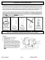
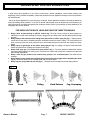
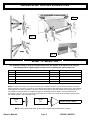
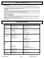
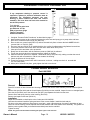
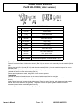
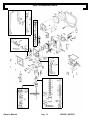
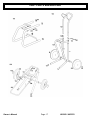
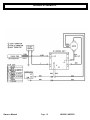
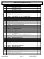
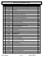
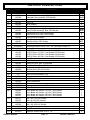
TABLE OF CONTENTS
Warranty Information
Important Safety Precautions
Introduction
Set Up, Priming, Spraying
Flushing & Priming
Shut Down and Pressure Relief Procedures
Airless Spray Painting Suggestions
Tip Selection
Troubleshooting
Repair Procedures
Piston Cartridge Assembly Repairs
Pressure Control Calibration
Prime Valve Service
Unit Parts Breakdown
Cart Parts Breakdown
Wiring Schematic
Parts List and Descriptions
Owner’s Manual
2
3
4
5
5
6
7-8
8-9
9
10-11
12-13
14
14-15
16
17
18
19-22
Page 1
HK3819 / HK5523
WARRANTY
H.E.R.O. WARRANTY
H.E.R.O., guarantees this airless pump to be free of defects in materials and workmanship to the
original owner, for a period of one full year from the date of purchase.
The warranty entitles the owner to parts replacement at no charge. The parts replacement
warranty is valid for any necessary replacement, weather caused by material or workmanship
defect or simple wear. H.E.R.O. Industries offers no warranty on the hoses, gun, tip or
accessories, plastic, rubber, other soft goods or motor used in or supplied with the H.E.R.O.
sprayer.
In addition to the general coverage listed above, a 5 YEAR WARRANTY is offered on the Drive
Train components. The drive train components are defined as the items contained within, but not
including, the “Drive Housing”. Drive motor and clutch not included.
Furthermore, this warranty does not cover, damage or wear caused by faulty installation, abrasion,
corrosion, inadequate or improper maintenance, negligence, or accident.
Motor, accessories, etc., which are supplied by other manufacturers and are attached to or
supplied with the H.E.R.O. airless pump, are warranted only to the extent that these parts are
warranted by their respective manufacturers. Warranty claims on these items must be made
directly to such manufacturers or their local authorized service depots.
The warranty is only applicable to the original purchaser and provided the equipment has been
properly used, operated and maintained in accordance with all instructions, precautions and
warnings contained in this manual. For the purpose of this warranty, damage resulting from
accident, abuse, improper cleaning, storage, fire, flood, or Act of God, is not covered.
H.E.R.O.’s liability is limited to replacing parts found to be defective or worn and does not include;
transportation costs, damage or other expenses of any kind incurred in connection with the
purchase and use of this sprayer.
Repairs claimed under warranty must be performed by an authorized H.E.R.O. Service Center,
using only genuine H.E.R.O. parts. Parts required under warranty will be supplied by your local H.
E.R.O. Service Center.
DO NOT return warranty parts to factory without authorization.
To qualify for the warranty, the warranty card (attached to this page) supplied with this H.E.R.O.
airless pump, must be completed with equipment serial number and signed by the purchaser, and
postmarked within ten (10) days of purchase.
Owner’s Manual
Page 2
HK3819 / HK5523
IMPORTANT SAFETY PRECAUTIONS
IMPORTANT
AS WITH ALL MECHANICAL EQUIPMENT, PROPER OPERATING AND MAINTENANCE
PROCEDURES ARE REQUIRED TO KEEP YOUR H.E.R.O. AIRLESS PUMP PERFORMING TO
YOUR SATISFACTION. THE FOLLOWING SAFETY, OPERATING AND MAINTENANCE
INSTRUCTIONS ARE IMPORTANT.
Read and understand this manual completely, especially with regard to all safety precautions. Read and follow
instructions on all warning labels on your equipment. Keep these warning labels clean and readable at all times.
Order new labels from your local distributor or from H.E.R.O. if needed.
This system is capable of producing 3000 psi (spray pressure). To avoid rupture and injury DO NOT operate this
pump with components rated less than 3000 psi working pressure (including but not limited to spray guns, hose
and connections).
Before servicing, cleaning or removal of any part, shut off power and relieve pressure.
WARNING
Prior to the use of the sprayer, ensure that the grounded continuity between the gun and the sprayer is
maintained. The hose shall be at least 50 feet in length. All hoses, guns, and accessories shall be suitable for
the maximum pressure ( 3000 PSI ). The gun shall be provided with a “Safety” which locks the trigger in the
“OFF” position. DO NOT point the gun at another person or spray at operator’s exposed skin. If there are any
special or unique conditions for this appliance, they shall be further noted and addressed and must be followed.
The manufacturer shall not be responsible for any loss, damages, or injury of any kind or nature whatsoever
resulting from the use of equipment other than in strict compliance with the instructions, cautions and warnings
contained in this operating and instruction manual and as displayed on the face of the equipment.
Never place fingers near spray tip of gun. Never point gun toward any part of the body, or that of any other
person. Material issuing from the spray tip is at high pressure. If fingers, or any part of the body are placed near
the tip of the spray gun, it is possible that the spray could break the skin and inject some of the material. If injury
does occur, seek the immediate medical attention. Be prepared to inform the doctor what fluid was injected,
if the injury is of an injection nature. Never treat the situation as a simple matter. Equipment and chemicals,
when used improperly can be dangerous.
IMPORTANT SAFETY PRECAUTIONS
NEVER place any part of the body in front of the spray tip or aim the gun toward any part of the body.
NEVER point the gun toward any individual.
NEVER treat any injury as a simple cut. If injury does occur, seek immediate medical attention. Be prepared to inform the doctor what fluid was injected.
NEVER allow another person to use the sprayer unless they are thoroughly instructed on its operation
and have read all safety precautions in this manual and all safety warning labels attached to unit.
NEVER use around children.
NEVER attempt to perform any maintenance or service on any part of the unit spray system without first;
1. Shutting the motor ON/OFF switch to OFF.
2. Relieving all pressure in the pump by triggering the gun.
3. Locking gun trigger in "LOCKED" position, with gun locked closed.
4. Open prime valve to drain.
NEVER operate the sprayer without the tip guard complete and in place.
NEVER spray any material in the vicinity of open flame, pilot lights, electrical outlets or any other source of
ignition.
NEVER spray volatile materials with flash points lower than 140 F (60 C).
Owner’s Manual
Page 3
HK3819 / HK5523
INTRODUCTION & UNPACKING
Congratulations on your purchase of a new H.E.R.O. H2K airless paint sprayer. We are sure you will enjoy owning and operating
your new sprayer. With H.E.R.O. airless spray equipment you will enjoy the features and benefits of this airless. You are spraying
paint, not air, and the paint is driven to the painting surface in a clean, fan shaped spray which penetrates all cracks and corners.
To attain these results, you must adjust the pressure as low as possible. We recommend that you become familiar with your
H.E.R.O. unit. Discuss with your dealer the useful accessory items they do offer - various types of tips, extension poles for hard to
reach areas, extra hose, etc. Use of accessory items is often the difference between a good job and an excellent one !
Your H.E.R.O. airless sprayer has been fully tested and carefully packaged to avoid damage. It should be carefully
examined upon arrival to determine that the unit shows no signs of freight damage. If any parts are found broken or
damaged, immediately contact the carrier and arrange for an inspection of the concealed damaged. Claims for
damage MUST be made by the CONSIGNEE and not the shipper. The carrier accepts full responsibility for the
safe delivery of merchandise upon pick-up from the shipper.
The unit shipping carton contains:
Gun & Hose
Package
50’ Hose, Airless
Gun, 517 Tip
(Optional)
EC-2560
Siphon Hose
Assembly
(S and C models)
EC-2600
Siphon Hose
Assembly
(H models)
EC-1000
Unitool
4-02-40-3PL1
Piston Lube
(8 Ounce Bottle)
SET UP, FLUSHING, PRIMING, SPRAYING, SHUT DOWN
Setting Up:
1. Attach siphon assembly to intake valve.
2. Connect Bleed hose to return fitting.
3. Attach gun to hose.
4. Attach paint hose to outgo nipple.
5. Check packing lubricant. This will help prevent
buildup of materials on the piston rod thus extending packing life. To add lubricant, tilt back unit and
insert pointed nozzle of the 3PL liquid into the slotted area in the front of the unit. Add only a small
amount . This should be done each time it is used.
Before each use, flush the pump with the correct
thinner for the paint being used. NOTE: The unit
MUST be stored with mineral spirits at all times.
Owner’s Manual
Page 4
HK3819 / HK5523
SETTING UP, FLUSHING, PRIMING, SPRAYING, SHUT DOWN
Flushing:
1. Have two pails ready; one for flushing fluid and one for waste.
2. If you are using latex paint, fill the flushing pail with approximately 1 gallon of warm soapy
water. For oil based paints, use approximately 1 gallon of mineral spirits.
3. Place the siphon hose in the “flushing” pail and the bleed tube in the “waste” pail.
4. Flip open prime valve lever (Ref # 60) to fully opened position, Or on older models turn
knob counter-clockwise to fully open position
5. Lower the pressure setting by turning the pressure control knob (Ref # 78) all the way
counter-clockwise.
6. Plug unit in outlet.
7. Turn unit on and slowly increase the pressure until the unit starts to run and “flushing” fluid
begins to exit the bleed hose.
8. Turn off unit and close the prime valve by flipping lever to closed position, or on older
models turn knob clockwise to fully closed position.
9. Place bleed hose back onto the siphon hose assembly.
10. Disengage gun trigger lock and trigger gun into waste container.
11. Start unit and trigger gun into the waste container until “flushing” fluid appears.
12. Move gun to “flushing” pail and resume triggering gun into pail. Re-circulate fluid for
approximately one to two minutes. Turn unit off.
13. Re-open the prime valve. Turn unit on and allow the “flushing” fluid to re-circulate through
bleed valve for approximately one minute. Turn unit off.
14. When spraying latex paint, repeat the “flushing” procedures with clear water. When
spraying oil based paints continue with “Priming” instructions.
Priming:
(Priming the sprayer follows the same basic step used in the “Flushing” procedures.)
1. Place the siphon hose in a clean 5 gallon pail. Install a strainer bag and secure with rubber
band. Keep strainer bag at least 4 inches from the bottom of pail.
2. Pour your paint through the strainer bag. Leave the strainer in place while spraying.
3. Place bleed tube in the “waste” pail.
4. Flip open prime valve lever (Ref # 60) to fully opened position. Or on older models turn
counter-clockwise fully to open position.
5. Lower the pressure setting by turning the pressure control knob (Ref # 78) all the way
counter-clockwise
6. Turn unit on and slowly increase the pressure until the unit starts to run and paint begins
to exit the bleed hose.
7. Close the prime valve by flipping back to closed position, or on older models turn knob
clockwise to fully closed position .
8. Place bleed hose back onto the siphon hose assembly.
9. Disengage gun trigger lock and trigger gun into waste container.
10. Start unit and trigger gun into the waste container until paint appears. Stop.
11. Move gun to the paint pail and resume triggering gun into pail. Re-circulate fluid for
approximately one to two minutes.
12. Turn unit off and follow the Pressure Relief Procedures
13. Install the tip guard and tip. You are now ready to start spraying.
Owner’s Manual
Page 5
HK3819 / HK5523
SPRAYING & SHUT DOWN
Spraying:
1. Turn unit on.
2. Trigger gun, and increase pressure slowly. Continue to increase the pressure until the spray
pattern is uniformed from top to bottom, with no heavy areas. If heavy areas are still visible at
maximum pressure settings, thin paint with the correct thinner, according to the paint manufacturer’s instructions. Spray test patterns onto old newspaper or other scrap material.
Always use the lowest possible pressure setting to atomize paint fully. Replace worn
tips immediately, as it is not possible to obtain satisfactory spray pattern with a worn
tip.
3. Check all fluid connection points for possible leaks. Correct before continuing.
4. Spray Paint. NOTE: For best results, read and practice the spray techniques shown on pages
6-7.
Shut Down:
1. Turn off unit.
2. Perform the Pressure Relief Procedures as shown on page 4.
3. Remove tip guard and gun filter. Place in your “flushing” bucket.
4. Perform the “Flushing” procedures as shown on page 5. Ensure you continue to flush the
sprayer until the “Flushing” fluid is running clear and no spray materials remain in the sprayer.
5. Before storing, the final “Flushing” rinse must be made with mineral spirits, regardless of what
is to be sprayed next. NEVER leave water or paint in the unit, even over night.
6. Clean tip guard, tip and gun filter. Re-assemble spray gun and store for next use.
Owner’s Manual
Page 6
HK3819 / HK5523
AIRLESS SPRAY PAINTING SUGGESTIONS
A good airless spray application is the result of many factors. Surface preparation, which includes cleaning and
degreasing, priming, material compatibility, quality finish product and correct application technique. All are all important to
the finished results.
The key to all good applications is a good spray gun technique. Proper application techniques can easily be learned by
using the following simple guidelines. If you are not familiar with the basic spray techniques we recommend that you
study this portion of the manual and practice the techniques shown. Practice your technique on scrap cardboard or old
newspaper until you feel confident.
FOR EXCELLENT RESULTS, READ AND PRACTICE THESE TECHNIQUES
1.
2.
3.
4.
5.
6.
7.
Always strain all paint through a H.E.R.O. strainer bag. The most common reason for airless sprayer’s to
malfunction is foreign matter jamming the valves or plugging the tip. Always strain the paint before putting through
the pump.
Always spray at the lowest pressure setting which will provide a uniform spray fan( fig. 1 ). Adjust pressure
control knob so that paint is completely atomized. Insufficient pressure will result in "tailing". Too much pressure will
result in excess fog and over spray, excess tip wear, and increased sprayer wear and tear. See setting up to spray,
page 8.
Always spray at right angles to the surface being sprayed ( fig. 2 ). Angling or arcing the nozzle toward the
surface will cause uneven coverage and excessive over spray.
Always hold spray gun 11-12 inches from spray surface( fig. 3 ). Too close and the fan width will be reduced
and material will be applied too heavily (runs). Too far from the surface and you will have excessive over spray and
light coverage (transparent).
Always move the gun parallel to the surface being sprayed, at a consistent speed. This avoids uneven
coverage.
Always start the spray stroke before triggering the gun and release the trigger before completing the stroke
( fig. 4 ).This avoids heavy build up of paint at either end of the spray stroke.
Always lap your spray pattern by one half( fig. 5 ). This assures full coverage of the surface being painted.
FIG. 1
Poor
Owner’s Manual
Good
Tailing
Page 7
Good Pattern
Fog, Overspray
HK3819 / HK5523
AIRLESS SPRAY PAINTING SUGGESTIONS
FIG. 4
FIG. 3
FIG. 5
SPRAY TIP SELECTION
It is advisable to obtain a spray tip recommendation from the supplier of the material to be sprayed.
The following table is a general guide and will assist in selecting the optimum tip to use.
TIP SIZE
USED TYPICALLY FOR SPRAYING THESE MATERIALS
APPROX. GPM
Suggested filter (color)
white
.019
Exterior Latex on large unobstructed areas.
.47
.017
Interior Latex, Exterior Latex, Shake Paint, Exterior Flat Paints.
.31
.015
Alkyd Flat Enamel, Interior Latex, Semi-Gloss Enamel, Stains.
.23
.013
Fine ground Gloss Enamels, and good quality Stains.
.18
.011
Clear Varnishes and Lacquers.
.12
NOTE: In order to test if a tip is worn, spray a small amount of suitable material on to a test surface and observe the spray
pattern produced on the wall. Try to obtain an even elliptical spray pattern by first adjusting the pressure down, then gradually
increasing pressure until full atomization is achieved. This should result in a crisp spray pattern with sharp edges and even
concentration, see diagram below. If a satisfactory pattern is unattainable ( look for edges to be rounded with heavier
concentration ), then the tip is worn and should be replaced. Other causes of poor spray fan are insufficient spray pressure
and material viscosity ( may requiring thinning ).
Good
Tip
Worn
Tip
Uneven Spray Pattern
NOTE: Use of excessively worn tip can result in apparent poor performance of pump.
Owner’s Manual
Page 8
HK3819 / HK5523
SPRAY TIP SELECTION
ORIFICE SIZE
All tips are rated by the size of the orifice or bore size. The bore size is measured in thousandths of an inch
( .017 = 17 thousandths of an inch ). The size of tip required is based on the consistency of the material to be sprayed.
The thicker the paint, the larger the tip size required. Always consult the product label or ask the paint retailer for the
manufacturer's recommendations with regard to proper tip sizes.
FAN WIDTH
Fan width or pattern width is determined by the spray tip's "fan width" classification. This size is measured in inches,
and is determined when spraying 12 inches from the spray surface and the tip of the gun. Various methods of noting
the fan widths are used by tip manufacturers. Ask your distributor for assistance.
NOTE: Two tips having the same tip size, but different fan widths will deliver the same amount of paint over a different
area (wider or narrower strip).
SPRAY TIP REPLACEMENT
During use, especially with Latex paint, high pressure and material abrasion will cause the orifice to grow larger. As the
orifice grows larger, the fan width grows smaller. Replace tips before they become excessively worn. Worn tips waste
paint, cause over spray, and decrease sprayer performance.
NOTE: When using Latex paint, a spray tip will wear at the rate of one size for approximately every 100 gallons of
material sprayed.
TROUBLESHOOTING
TROUBLE
Motor will not
start or run
Motor runs,
but
Poor unit performance.
Low or Erratic
Output / Pressure
POSSIBLE CAUSE
REMEDY
1. Unit unplugged.
2. Unit not switched “ON”
3. Pump at full pressure.
4. Pressure Control set too low.
5. Fuses on motor controller.
1. Plug unit in to a 120V, 60HZ,
2. Flip On/Off switch to ON
3. Follow “pressure relief instructions”
4. Slowly increase pressure until motor starts.
5. Replace if necessary
1. Fault in pump section.
2. Worn spray tip.
3. Improper tip size.
4. Material too viscous( thick ).
5. Gun filter clogged
1. See fluid section repairs.
2. Replace tip.
3. Replace tip.
4. Thin material with appropriate thinners, per product manufacturer’s
instructions.
5. Clean or replace filter.
6. Repair or replace valve
6. Prime valve leaking
1. Air leaks or blockages.
2. Worn Packings, Intake or Outgo balls and / or
seats.
3. Cylinder sleeve leakage.
4. Worn spray tip.
5. Cylinder O-Rings worn or damaged
6. Prime valve leaking
1. Check the following;
1. Worn packings.
2. Air leak.
1. Re-pack pump.
2. Check the following;
⇒
⇒
⇒
Plugged intake screen.
Intake O-ring.
2. Re-pack pump.
3. Replace piston valve O-Rings.
4. Change tip.
5. Replace Cylinder O-Rings.
6. Repair or replace valve
⇒
⇒
⇒
Unit does not
prime
Intake tube fitting.
Intake tube connections.
Plugged intake screen.
Intake O-ring.
3. Add paint to pail.
4. Disassemble and clean.
5. Thin material with appropriate thinners, per product
manufactures .instructions
6. Replace worn balls and / or seats. Clean
3. Paint level too low.
4. Prime Valve clogged.
5. Paint too thick.
6. Valve ball stuck or glued.
No Output
1. Pump not primed.
2. Pump needs rebuilding.
3. Broken drive parts;
con-rod pin, piston rod, valve.
1. Prime pump.
2. Rebuild pump.
3. Repair as required.
Fluid leaks from front
drive housing.
1. Worn upper packings.
2. Leaking transducer.
1. Replace packings.
2. Replace transducer seals.
Owner’s Manual
Page 9
HK3819 / HK5523
REPAIR PROCEDURES
The H.E.R.O. H2K units were specifically designed to assist the operator in dealing with the inconvenient, time
consuming, and some times technically challenging concept of equipment service and repair. The H2K models
offer simple, quick, easy to perform procedures for any and all the fluid section repair procedures. Servicing and
the repair of the fluid section can be performed with one simple tool, the H.E.R.O. “UNI-TOOL™” , (Part #
HK1000). The complete fluid section can be removed and replaced in less than 5 minutes.
HK2500C
HK1000
FLUID SECTION
Tip the entire unit back into a vertical position,
this provides greater access to the fluid section, while making repairs.
1. Complete “Pressure Relief Procedures” as described on page 4
2. Unplug unit from electrical source.
3. Remove the siphon assembly from bottom of intake valve, by pushing the release clip off to one side and pulling
assembly away from the valve. NOTE: Bleed hose does not need be removed while servicing, however you may
find it convenient to do so.
4. Using the 1/4” Hex key of your H.E.R.O. Uni-Tool (Part # HK1000, supplied with each unit), loosen the four manifold
bolts counter clockwise 1/2 a turn as shown in Fig # 1.
5. Insert the 3/8” Hex key side of the Uni-Tool and remove the entire intake valve assembly by turning it counter
clockwise as shown in Fig # 2.
Fig # 1
Fig # 3
Fig # 2
Continued on page 10.
Owner’s Manual
Page 10
HK3819 / HK5523
REPAIR PROCEDURES
6. Using the 5/8” socket end of the Uni-Tool, remove the entire fluid section assembly as shown in Fig # 4 and #
5 by turning it counter clockwise until it is fully removed from connecting rod and manifold.
Fig # 6
Fig # 4
Fig # 5
The entire fluid section is now removed, awaiting further repairs or service. Refer to the various service repairs on
the pages to follow. See page below for intake valve repairs, pages 10-11 for piston rod, cylinder, packing kit
assembly repairs, page 11-12 for whole piston rod, cylinder, packing kit assembly replacement and unit
re-assembly.
INTAKE VALVE ASSEMBLY REPAIRS
Simple cleaning and debris removal can be undertaken without dismantling the entire intake valve
assembly. For component replacement, see disassembly and re-assembly instruction to follow
DIS-ASSEMBLY
Using the flat hex sides, place Inlet Fitting (Ref # 27) in a vise or hold securely with
adjustable wrench. Use the Uni-Tool or a 3/8 allen key to remove the intake housing
(Ref # 34) from the inlet fitting. Inspect all part for wear or damage.
RE-ASSEMBLY
1. Install intake crush washer (Ref # 33) into the intake housing (Ref # 34).
2. Insert Intake Seat (Ref # 32) into the intake housing, ensuring The beveled
side of seat faces upwards.
3. Place the intake ball (Ref # 31) on to the intake seat. (Ref # 32)
4. Install the ball stop (Ref # 30) into the ball guide (Ref # 29), and place entire
assembly into the intake housing (Ref # 34).
5. Apply Teflon pipe sealant or Teflon tape to the threads of the intake housing.
(Ref # 34).
6. Drop inlet washer (Ref # 28) into the intake fitting (Ref # 27).
7. Screw the intake housing assembly into the intake fitting. Tighten to 100 foot
pounds. Slide the O-ring (Ref # 26) onto the intake fitting.
If the removal and repair of the intake valve is the only service preformed, continue by
threading the intake valve assembly into the intake manifold (Ref # 39). Secure to 30
foot pounds. If piston valve repairs are to be performed, complete these before
performing.
Owner’s Manual
Page 11
HK3819 / HK5523
REPAIR PROCEDURES
PISTON CARTRIDGE ASSEMBLY REPAIRS – DISMANTLING
The piston cartridge assembly is available as a complete, pre-assembled cartridge for quick, on site, unit
repairs. Items are also available individually for more economical repairs when time is not of the essence.
We recommend keeping a new or previously re-build piston cartridge assembly in your tool box at all times,
for those urgent on the job replacements. The used or worn piston cartridge assemblies can then be repaired
at a more convenient time.
Remove the “Piston Cartridge Assembly” as per the
instructions on page 9
1. To dismantle the piston cartridge assembly, push the
piston valve body (Ref # 13), down through the
cylinder (Ref # 21). This will remove all items marked
Ref # 12 through 18. Note upper packings will remain
in the cylinder Ref # 21.
2. Remove upper packings from cylinder.
3. Remove piston sleeve (Ref # 12) from piston valve
body (Ref #13).
4. Remove lower packings from piston valve body.
5. Place piston valve body (Ref # 13) in vise or secure
firmly with a 5/8’’ wrench, and use the Uni-Tool to
remove the seat (Ref # 18) from the piston valve body
(Ref # 13).
6. Remove the piston seat (Ref # 18), piston seat
washer (Ref # 17) and ball (Ref # 16) from the piston
valve body.
Owner’s Manual
Page 12
HK3819 / HK5523
REPAIR PROCEDURES
PISTON CARTRIDGE ASSEMBLY REPAIRS – ASSEMBLY
1. Slide o-rings (Ref # 14 & 15) onto the piston valve body (Ref # 13). It is recommended to lubricate with a
common grease or piston lube before sliding on.
2. Drop ball (Ref # 16) into piston valve.
3. Insert piston valve washer (Ref # 17) into piston valve.
4. Apply Loc-Tite 271 (Red) to threads of seat (Ref # 13), and screw tight using your Uni-Tool.
5. Apply a small amount of grease (common grease or piston lube) into the “V” portion of each packing set
component. Re-assemble and squeeze packing set together. Remove any excess grease (leave a small
portion) from the outer perimeter. NOTE: Our testing has shown that a longer packing life is obtained when
the seals are pre-lubricated in the manner described above.
6. Slide the lubricated, lower packing assembly onto piston valve.
7. Slide the flat washer onto piston valve.
8. Slide piston sleeve (Ref # 12) onto piston valve, with the four (4) holes closest to the lower packings.
9. Assemble the back up ring (Ref # 19) and cylinder o-ring (Ref # 20) onto cylinder. The cylinder o-rings are
always placed on the inner side of the cylinder, facing each other. Back up o-rings are always on the outer
side of the cylinder (Far ends).
10. Slide cylinder (Ref # 21) over the piston valve and lower packings. Ensure the cylinder four (4) outlet holes
are at the top (refer to diagram).
11. Insert upper cylinder clip (Ref # 22) into the cylinder. NOTE: This clip will remain in the cylinder during
dismantling and needn’t be removed.
12. Slide the lubricated, upper packing assembly (see step 7 & 8) into the cylinder until only approximately 1/8”
of packings is exposed above the cylinder.
13. With piston cartridge assembly fully assembled, move back to the unit and tighten the four (4) intake
manifold bolts (Ref # 38) to 30 foot pounds or with Uni-tool as shown in Fig # 1. (Loosened in step 4 of
removal instruction on page 9).
14. Insert the fully assembled piston cartridge assembly (Ref # 11) into the manifold (Ref # 39) and thread into
the con-rod coupler (Ref # 69) as shown in Fig # 2. Tighten to 30 foot pounds.
15. Install intake valve assembly (Ref # 25) as shown in Fig # 3 & 4.
16. Re-attach intake siphon assembly and repairs are complete.
Fig #1
Fig #2
Fig #4
Fig #3
Owner’s Manual
Page 13
HK3819 / HK5523
PRESSURE CONTROL CALIBRATION
If any component relating to pressure control is
repaired or replaced, a pressure calibration must be
performed. For illustration purposes, the gear
housing is shown without the cover and con-rod
assembly. The cover does not have to be removed to
set the unit pressure.
Tools Needed
50' nylon airless paint hose
gun with new .017 tip
4000 psi pressure gauge
Two 3/4" wrenches
flathead screwdriver
1.
2.
3.
4.
5.
6.
7.
8.
9.
10.
11.
12.
13.
104
Complete “Pressure Relief Procedures” as described on page 4
Install pressure gauge at the connection between the paint hose and spray gun or pump outlet and hose.
Place a 3/4” wrench on knob locking nut (Ref # 80).
Place a cloth over control knob (Ref # 81) and use channel lock pliers to loosen the knob. NOTE: Knob is
secured with Loc-Tite 222. (Red)
The top of the stem (Ref # 78) is machined with a slot, to allow for adjustments using flathead screw driver.
Thread the pressure control stem down until the motor starts allow unit to prime.
Close prime valve and allow unit to pressurize.
Slowly turn the stem down until the maximum pressure (3000 psi) is achieved.
Trigger the gun and check the maximum pressure, adjust as needed.
Once the maximum pressure is adjusted. Thread down the top nut (Ref # 80), making sure that the stem is
held securely with a screwdriver, until the nut contacts the housing.
Check the pressure of the unit again.
Thread the pressure control knob until it bottoms out on the nut , making sure that it is secured with
Loc-Tite # 222 (Red)
With a pair of channel lock pliers, gently tighten the knob on to the nut.
PRIME VALVE SERVICE
Part # HK-3600
Removal
Place 5/8” wrench on flats of bleed valve housing (Ref # 65) and remove valve assembly from the manifold (Ref #
39).
Remove the seat (Ref # 60) and the Crush Washer (Ref # 59) from the manifold. Inspect for worn or damaged parts.
Drive the pin (Ref # 66) out of the valve lever (Ref # 67) and separate the knob from the stem.
Remove stem and spring from the valve housing. (Ref # 65)
Remove and replace stem seal (Ref # 61).
Installation
Repair kit is available to rebuild prime valve. Order part # HK-3600RK
Lubricate the seal and install the spring and stem in the reverse fashion. Install the knob and pin.
Flip lever to the open position to allow stem to move back, apply a liberal amount of grease to both sides of seat.
Place into end of housing, with the tapered end towards the ball. Add crush washer to the assembly. The grease will
hold the parts to gather while you thread the assembled parts into the manifold.
Tighten securely.
NOTE: The grease will be flushed out during the prime cycle on the next use.
Owner’s Manual
Page 14
HK3819 / HK5523
PRIME VALVE SERVICE
Part # HK-3500B ( older version )
HK-3500B PRIME VALVE
Ref #
Part #
Description
1
11A-3CP
Crush washer
2
11A-4
Prime valve seat
3
11A-5TC
Prime valve ball, tungsten carbide
4
HK-3005
Prime valve housing
5
02-22-2007
Body o-ring
6
606-8
Stem o-ring
7
606-15
Back up ring
8
HK-3010
Prime valve stem
9
HK-3020
Pin, Prime valve knob
10
HK-3015
Knob, prime valve
11
HK-3030
Label, “close”
*
HK-3600BRK
Prime Valve Repair Kit, Includes Ref # 1-3, 5-7
Removal
Place 5/8” wrench on flats of bleed valve housing (Ref # 4) and remove valve assembly from the manifold (Ref #
39).
Remove the ball (Ref # 3) seat (Ref # 2) and the crush washer (Ref # 1) from the manifold. Inspect for worn or
damaged parts.
Drive the roll pin (Ref # 9) out of the valve knob (Ref # 10) and separate the knob from the stem.
Unthread the stem from the valve housing (Ref # 4).
Remove and replace stem seals, taking note of their correct sequence
Installation
Lubricate the seals and install the stem in the reverse fashion. Install the knob and pin.
Thread the valve knob through the housing counter clockwise until it bottoms out. Drop new ball into valve
housing.
Apply a liberal amount of grease to both sides of seat. Place into end of housing, with the tapered end towards
the ball. Add crush washer to the assembly. The grease will hold the parts to gather while you thread the
assembled parts into the manifold. Tighten securely.
NOTE: The grease will be flushed out during the prime cycle on the next use.
Owner’s Manual
Page 15
HK3819 / HK5523
PARTS BREAKDOWN
Owner’s Manual
Page 16
HK3819 / HK5523
CART PARTS BREAKDOWN
Owner’s Manual
Page 17
HK3819 / HK5523
WIRING SCHEMATIC
Owner’s Manual
Page 18
HK3819 / HK5523
PARTS LIST & DESCRIPTIONS
REF#
PART #
1
HK2560
2
3
4
5
6
7
8
9
10
11
12
13
14
15
16
17
18
19
20
21
22
23
24
25
26
27
28
29
30
31
32
33
34
35
36
37
38
39
40
DESCRIPTION
QTY
Siphon Hose Assembly, Sled and Low Boy Models,
Includes Ref # 1,3 -7,9,10
HK2600
Siphon Hose Assembly, High Boy Models,
Includes Ref # 2 - 6,8 -10
187F
Siphon Screen, Fine Mesh
HK2035
O-Ring, Quick Disconnect
HK2030
Spring, Quick Disconnect
HK2025
Retainer, Quick Disconnect
HK2570
Prime Tubing, 3/8” O.D X 42”, Sled and Low Boy Models
HK2630
Prime Tubing, 3/8” O.D X 15 -1/2”, High Boy Models
HK3027
Compression Sleeve, Prime Valve Fitting
HK3026
Compression Nut, Prime Valve Fitting
HK2500C Fluid Cartridge Assembly, Includes Ref # 12 - 23
HK2195
Piston Sleeve, SS
HK2190
Piston Valve Body
HK2055
Piston Valve Body O-Ring
HK2220
Piston Valve Body O-Ring (Brown)
667-43-3
Piston Valve Ball, 1/4”
HK2060
Piston Valve Seat Washer
HK2605
Piston Valve Seat
HK2100
Cylinder Back Up Washer
HK2095
Cylinder O-Ring
HK2200
Cylinder, SS
HK2215
Cylinder Retaining Clip
HK2510C Packing Repair Kit,
Includes Ref # 14, 15, 16, 17, 19, 20, 23, 26, 28, 31, 33
HK2520C Packing Overhaul Kit, Includes Ref # 12, 21, 23
HK2590
Intake Valve Assembly, Includes Ref # 26 - 34
HK2150
Intake Valve Housing O-Ring
HK2130
Intake Valve Housing
HK2160
Intake Valve Crush Washer
HK2155
Intake Valve Ball Guide
02-40-2005 Intake Valve Ball Guide Stop
02-40-2004 Intake Valve Ball
HK2145
Intake Valve Seat
HK2165
Intake Valve Seat Crush Washer
HK2140
Intake Valve Inlet Fitting
HK1000
Hero “Unitool™” H2K Repair Tool
4-02-40-3PL1 Pump Packing Lubricant, 8 oz. Bottle
3-1
High Collar Lock Washer, 5/16”
HW1077
Capscrew, Socket Head, 5/16” x 2-1/4”, Grade 8
HK2170
Manifold, Sled & Low Boy Units
HK2230
Manifold, High Boy Models
HK2185
Seal Washer
Owner’s Manual
Page 19
HK3819 / HK5523
1
1
1
1
1
1
1
1
1
1
ASSY
1
1
1
1
1
1
1
2
2
1
1
KIT
KIT
ASSY
1
1
1
1
1
1
1
1
1
1
1
4
4
1
1
1
PARTS LIST & DESCRIPTIONS
REF#
PART #
DESCRIPTION
QTY
41
42
43
44
45
46
47
48
49
50
51
52
53
54
55
56
57
58
59
60
61
62
63
64
65
66
67
68
69
70
71
05-40-5020
HK3025
HK3035
14A
HK5625
02-40-2004
HK5115
HK5205
HK5240
HK5215
HK52101
HK5225
HK5200
HK5715
HK6555
3-1
HW1060P
HK3600
11A-3CP
HK3040
HK2055
HK3605
HK3060
02-22-2007
HK3045
HK3070
HK3015
HK3600RK
HK5635
HK2095
HK5650
HK5660
HK5665
HK5090
HW5021P
HK5250
HK5310
HW5050P
HK5670
HW4075P
HW4077P
HW5080
DEC-MAXPRE RD
Dowel Pin
Prime Hose Elbow Fitting, Includes Ref #9 &10, Sled & Low Boy Models
Prime Hose Fitting, Includes Ref #9 &10, High Boy Models
Outlet Fitting
Pressure Transducer Assembly, Includes Ref # 46-53
Pressure Transducer Ball
Pressure Transducer Housing
Pressure Transducer Housing O-Ring
Pressure Transducer Stem O-Ring
Pressure Transducer Stem
Pressure Transducer Stem Back Up Ring
Pressure Transducer Stem O-Ring
Pressure Transducer Crush Washer
Pressure Transducer Repair Kit, Includes Ref # 48, 49, 51-53
Pail Hook, High Boy Models
High Collar Lock Washer, 5/16”
Capscrew, Socket Head, 5/16” x 3/4”
Prime Valve Assembly, Includes Ref # 59-67
Prime Valve Crush Washer
Prime Valve Seat
Prime Valve Stem O-Ring
Prime Valve Stem
Prime Valve Spring
Prime Valve Housing O-Ring
Prime Valve Housing
Prime Valve Pin
Prime Valve Lever
Prime Valve Repair Kit, Includes Ref # 59-64,
Con-Rod Coupler Assembly
Con-Rod Coupler O-Ring
Drive Housing, Red, 3819 Models
Drive Housing, Blue, 5523 Models
Pressure Sensor Assembly, Includes Ref # 73-82
Pressure Sensor Rod
Pressure Sensor Flat Washer
Pressure Sensor Spring Sleeve
Pressure Sensor Spring
Pressure Sensor Stem Washer
Pressure Sensor Stem
Pressure Sensor Lower Jam Nut
Pressure Sensor Upper Jam Nut
Pressure Sensor Adjustment Knob
Decal “Maximum Pressure”
1
1
1
1
ASSY
1
1
1
1
1
1
1
1
KIT
1
2
2
ASSY
1
1
1
1
1
1
1
1
1
KIT
ASSY
1
1
1
ASSY
1
1
2
1
1
1
1
1
1
1
72
73
74
75
76
77
78
79
80
81
82
Owner’s Manual
Page 20
HK3819 / HK5523
PARTS LIST & DESCRIPTIONS
REF#
PART #
83
84
05-40-5012
HK5525
HK5530
05-40-5015
HK5155
HK5055
HK5505
HK5545
HK5550
HK5452
HK5454
HK5450
HK5456
HK5457
HK5458
HW30062P
DEC-H2K-WARN
HK5140
HK5145
HK5315
HK5320
HK5460
HK5466
HK5462
HK5464
HK5600
HK5602
05-700-5173
3-1
HW1079
HK5160
HK5165
HK5105
HW30055
HK6015
HK5645
HK5647
HK5655
HK5657
HK5171
HK5327
HK5172
HK5326
DEC-H2K-WARN
HW50081
HW3021
85
86
87
88
89
90
91
92
93
94
95
96
97
98
99
100
101
102
103
104
105
106
107
108
109
110
111
112
113
114
Owner’s Manual
DESCRIPTION
QTY
Thrust Washer
Crankshaft Gear Assembly, 3819 Models
Crankshaft Gear Assembly, 5523 Models
Thrust Washer
Dowel Pin
Thrust Washer
Reduction Gear Assembly
Motor End Bell Assembly, Red, 3819 Models
Motor End Bell Assembly, Blue, 5523 Models
Motor Brush Cover, Red, 3819 Models
Motor Brush Cover, Blue, 5523 Models
Motor Brush Cover Screw
Motor Brush Set, 3819 Models
Motor Brush Set, 5523 Models
Motor Brush Holder, Includes Ref # 94
Motor Brush Holder Screw, 6-32 x 1/4” Pan Head Phillips, SS
Warning Decal
.6 HP DC Motor 110 VAC, Less Endbell, 3819 Models
.9 HP DC Motor 110 VAC, Less Endbell, 5523 Models
.6 HP DC Motor 220 VAC, Less Endbell, 3819 Models
.9 HP DC Motor 220 VAC, Less Endbell, 5523 Models
Motor Fan
Motor Fan Cover Screw
Motor Fan Cover, Red, 3819 Models
Motor Fan Cover, Blue, 5523 Models
Electrical Cord, 110 VAC Models
Electrical Cord, 220 VAC Models
Electrical Cord Connector
High Collar Lock Washer, 5/16”
Capscrew, Socket Head, 5/16” x 3”, Grade 8
On/Off Switch
On/Off Switch Boot
Micro Switch
Capscrew, Socket Head, 4-40” x 3/4”
Circuit Board Gasket
Circuit Board with Gasket, 110 VAC, 3819 Models
Circuit Board with Gasket, 110 VAC, 5523 Models
Circuit Board with Gasket, 220 VAC, 3819 Models
Circuit Board with Gasket, 220 VAC, 5523 Models
Fuse, 15A, 110 VAC Models
Fuse, 8A, 220 VAC Models
Fuse, 25A, 110 VAC Models
Fuse, 12A, 220 VAC Models
Warning Decal
High Collar Lock Washer, #8
Capscrew, Socket Head, 8/32” x 1/2”
Page 21
HK3819 / HK5523
1
ASSY
ASSY
1
2
2
ASSY
ASSY
ASSY
2
2
2
KIT
KIT
1
4
1
1
1
1
1
1
3
1
1
1
1
1
2
2
1
1
1
2
1
1
1
1
1
1
1
1
1
1
4
4
PARTS LIST & DESCRIPTIONS
REF#
PART #
115
117
118
119
120
121
122
HK6535
HK6540
DEC-3819
DEC-5523
HW3021
HK6520
3-1
HW1077
HK6020
HK6560
123
124
125
126
127
128
06-40-6000
633F
HK6550
67/16A
HW6088
HK6530
129
130
131
HK6030
HK6025
HK6510
132
133
134
135
136
HK6055
HK6070
HK6060
HK6515
HW30062P
116
Owner’s Manual
DESCRIPTION
QTY
Gear Housing Cover with Decal, 3819 Models
Gear Housing Cover with Decal, 5523 Models
Front Label, 3819 Models
Front Label, 3819 Models
Capscrew, Socket Head, 8/32” x 1/2”
Sled Cart Assembly, Includes Ref # 121
High Collar Lock Washer, 5/16”
Capscrew, Socket Head, 5/16” x 2-1/4”, Grade 8
End Caps, 1-1/4”, All H2K Models
High Boy Cart Assembly,
Includes Ref # 121, 123, 124, 125, 126, 127
Sliding Handle, High Boy Models
Sliding Handle Spring Clip, High Models
High Boy Cart Less Ref # 121, 123, 124, 126, 127
10” Pneumatic Wheel
Axle Caps, 5/8”, High & Low Boy Models
Low Boy Cart Assembly,
Includes Ref # 121, 127, 129, 130, 131, 132, 133, 134, 135, 136,
Wheel Hub Cap, Low Boy Models
Wheel, Less Hub Cap, Low Boy Models
Low Boy Cart
Less Ref # 121, 127, 129, 130, 132, 133, 134, 135, 136,
Sliding Handle Insert, Low Boy Models
Sliding Handle Spring Clip, Low Boy Models
Sliding Handle Pin, Low Boy Models
Sliding Handle, Low Boy Models
Machine Screw, 6-32 x 1/4” Pan Head Phillips
Page 22
HK3819 / HK5523
1
1
1
1
4
ASSY
2
2
2 or 4
ASSY
1
2
1
2
2
ASSY
2
2
1
2
2
2
1
2
MANUFACTURED BY:
H.E.R.O.
2719 LAKE CITY WAY
BURNABY, B.C.
CANADA
PHONE: 604-420-6543
800-494-4376
FAX:
604-420-8725
PURCHASED FROM
__________________________
__________________________
__________________________
__________________________
MODEL: ___________________
SERIAL #: _________________
DATE OF PURCHASE:
________________
Owner’s Manual
Page 23
HK3819 / HK5523
Version 5 Dec 2005
SAFETY AND OPERATING MANUAL
WARNING: DO NOT OPERATE THIS EQUIPMENT WITHOUT READING
AND UNDERSTANDING ALL SAFETY AND OPERATING INSTRUCTIONS
SEE PAGES 3 – 8
FACTORY LOCATED AT:
720 EATON WAY
DELTA, B.C. CANADA
V3M 6J9
PHONE: (604) 522-6543
Owner’s Manual
www.hero.ca
FAX: (604)
522-8735
Page
24
U.S.A ADDRESS:
P.O. BOX 75
CUSTER, WASHINGTON
98240-0075
TOLL HK3819
FREE: (800)
494-4376
/ HK5523