1
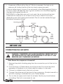
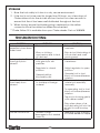
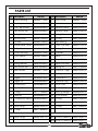
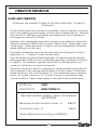
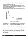
1” IMPACT WRENCH
Model No: CAT47
Model No: 3110640
OPERATING & MAINTENANCE
INSTRUCTIONS
GC0414
INTRODUCTION
Thank you for purchasing this CLARKE Impact Wrench.
Before attempting to operate the machine, it is essential that you read this
manual thoroughly and carefully follow all instructions given. In doing so you
will ensure the safety of yourself and that of others around you, and you can
also look forward to the product giving you long and satisfactory service.
GUARANTEE
This CLARKE product is guaranteed against faulty manufacture for a period of
12 months from the date of purchase. Please keep your receipt as proof of
purchase.
This guarantee is invalid if the product is found to have been abused or
tampered with in any way, or not used for the purpose for which it was
intended.
Faulty goods should be returned to their place of purchase, no product can
be returned to us without prior permission.
This guarantee does not effect your statutory rights.
TECHNICAL SPECIFICATION
Feature
Specification
Weight
14.6 kg
Airline Connection size
1/2" BSP
Air Hose Requirement
1/2" BSP / 12.7mm dia
Maximum Air Pressure requirement
90psi (6.2bar)
Maximum speed
3500 rpm
Max tightening torque
1400 ft. lb
Nominal Air Consumption
7.4 cfm
Sound pressure
96 dB(A)
Please note that the details and specifications contained herein, are correct
at the time of going to print. However, Clarke International reserve the right to
change specifications at any time without prior notice.
2
SAFETY PRECAUTIONS
WORK ENVIRONMENT
1. Keep the work area clean and tidy.
2. Dress appropriately - do not wear loose clothing or jewellery. Tie long hair
out of the way.
3. Keep children and visitors away - do not let children handle the wrench.
Make sure that any other persons in the work area are suitably dressed
and are wearing eye and ear protection.
4. Keep the work area well lit.
5. Although the impact wrench may be used outdoors, do not leave it
exposed to the elements. Avoid direct sunlight, direct heat, rain/moisture
etc.
6. Keep the air supply hose away from sources of heat, oil and sharp edges.
7. Do not fit the wrench to a stand or clamping device that may damage it.
GENERAL USE
1. Always stay alert and use common sense - do not use this product when
you are tired or under the influence of alcohol or medication.
2. Always wear eye protection when using the impact wrench to provide
protection from flying particles from the front and the side.
3. Always wear ear protectors when using the impact wrench.
4. Do not over-reach. Keep proper footing and balance at all times.
5. Never use any type of bottled gas as a source of power for the wrench.
6. Do not connect the air supply hose with your finger on the trigger
7. Do not exceed the maximum pressure for the wrench: (90 psi / 6.2 bar).
8. Check air hoses for leaks or worn condition before use, and ensure that all
connections are secure.
9. Do not use the wrench for any purpose other than that described in these
instructions.
10. Never carry out any alterations or modifications to this product.
11 Always disconnect from the air supply when:
Performing any maintenance
The wrench is not in use
The wrench will be left unattended
Moving to another work area
Passing the wrench to another person.
3
12. Never force or misuse the tool. It will do a better and safer job at the rate
for which it was designed.
12. Never use this product if it is defective/operating abnormally.
13. Never carry the wrench with your finger on the trigger.
14. Quick change couplings should not be located at the tool. They add
weight and could fail due to vibration.
15. Always check the wrench for any damage or any condition that could
affect its operation. Any damaged part should be properly repaired.
16. Never attempt any repairs yourself. If you have a problem with this
product contact your local Clarke dealer.
17. This product vibrates during use. Vibration may be harmful to your hands
or arms. Stop using the machine if discomfort, a tingling feeling or pain
occurs and seek medical advice before resuming use.
IMPACT WRENCH SAFETY INSTRUCTIONS
1. Always use the impact wrench in the manner and for the functions
described in these instructions.
2. Always ensure the wrench is not moving and disconnected from the air
supply when changing sockets etc. Use only Impact Wrench sockets....DO
NOT use standard sockets.
3. Always finish tightening wheel nuts or engine parts with a torque wrench or
suitable spanner to the correct torque as recommended by the vehicle
manufacturer.
4. Always avoid excessive use of the impact wrench. When tightening a nut
or bolt, never allow the wrench to impact more than 8 times - to avoid
over tightening - 3 to 4 impacts is normally sufficient.
5. Always ensure that the socket is correctly installed before switching on.
6. Always only use sockets which are specified for impact wrench use.
7. Due to the possible presence of asbestos dust from brake linings, always
wear suitable respiratory protection.
8. Never carry the impact wrench by the air supply hose.
9. Always disconnect from the air supply when changing bits or when the
wrench is not required for immediate use in order to avoid accidental
starting.
10. Always store this product in a dry, secure place out of reach of children or
untrained users.
11. Always use both hands to control the impact wrench.
12. Always ensure the wrench has stopped before putting it down after use.
Additionally, please keep these instructions in a safe place for future reference.
4
INTRODUCTION
The CAT47 is a professional, 2-hammer, 1” square drive impact wrench with an
extended anvil.
1.
1” Square Socket Drive
2.
Side handle
3.
Forward/Reverse clutch
4.
Airline Connection
5.
Trigger
1
2
3
4
5
AIR SUPPLY REQUIREMENTS
WARNING: COMPRESSED AIR CAN BE DANGEROUS. ENSURE THAT YOU
ARE THOROUGHLY FAMILIAR WITH ALL PRECAUTIONS RELATING TO THE
USE OF COMPRESSORS AND COMPRESSED AIR SUPPLY.
• Use only clean, dry, regulated compressed air as a power source.
• Air compressors used with the tool must comply with the appropriate
European Community safety directives.
• A build-up of moisture in the air compressor will accelerate wear and
corrosion in the moving parts. Ensure any moisture is drained from the
compressor daily, and the inlet filter is kept clean.
• If an unusually long air hose is required, (over 8 metres), line pressure may
need to be increased.
• Never exceed the maximum operating pressure for the tool.
• The air hose must be rated at least 150% of the maximum operating
pressure of the tool.
5
• A pressure of 90 psi with a flow of 7.44 cfm is required. Too high an air
pressure will shorten the life of the tool due to excessive wear.
A typical airline layout is shown. If an automatic in-line filter/regulator/lubricator unit is used it will keep the tool in good condition, but should be regularly
checked and topped up with oil.
IMPORTANT: If a filter/lubricator unit is not used, the air tool should be lubricated with 2 to 6 drops of oil, at least once a day or after 2 hours work,
depending upon the working environment. The oil can be inserted through
the airline connection fitting.
BEFORE USE
CONNECTING THE AIR SUPPLY
WARNING: COMPRESSED AIR CAN BE DANGEROUS. ENSURE THAT YOU
ARE FAMILIAR WITH ALL PRECAUTIONS RELATING TO THE USE OF COMPRESSORS AND COMPRESSED AIR SUPPLIES.
Note: Ensure the compressor is turned off.
1. Remove the plastic blanking plug from the connection port of the tool as
shown.
2. Pour 2-3 drops of Clarke airline oil into the air inlet. This should be done
regardless of whether or not a lubricated air supply is to be used.
3. Connect a suitable hose to the tool as shown.
4. Connect the other end of the hose to the compressor. (A whip hose with a
quick fit coupling is available from your Clarke dealer).
5. Turn on the air supply and check for air leaks. Rectify any found before
proceding. The tool is now ready for use.
6
OPERATION
CAUTION: ALWAYS BE SURE THAT THE TOOL IS OFF BEFORE ATTACHING
OR REMOVING A SOCKET. ALWAYS TAKE CARE TO USE THE CORRECT
SIZE SOCKET FOR BOLTS AND NUTS. AN INCORRECT SOCKET WILL CAUSE
DAMAGE TO THE BOLT OR NUT.
1. The side handle is supplied loose and must be fitted to the impact wrench
using the bolt provided.
2. Select an appropriate impact socket, which must be in good condition,
and fits the anvil and nut closely. Use only 1”square drive impact wrench
sockets. (NEVER use standard hand sockets).
3. Select Forward or Reverse drive by moving the lever, on the base of the
wrench, to the ‘F’ or ‘R’ position. Always check the direction of rotation
before operation. Select the appropriate lever when the spindle is
moving.
4. Squeeze the trigger to start the wrench. Release the trigger to stop.
5. Turn the airline regulator to its lowest setting, then apply the wrench to a
nut or bolt of known tightness (or torque setting), size, thread pitch, and
thread condition as those on the job.
6. Start the wrench, in the FORWARD position, and gradually turn the air
regulator until the nut or bolt moves very slightly in the direction in which it
was set. The tool is now set to duplicate that tightness. For future use, note
that specific setting.
7. When critical torque values are not required, turn nut or bolt until it fits
snugly, and then turn a further one quarter to one half a turn - slightly
more if gaskets are used between surfaces.
8. For additional power during disassembly work, turn the air line regulator to
its highest setting.
This tool is rated at 1" bolt size, and is downgraded for spring ‘U’ bolts, tie
bolts, long cap screws, double depth nuts, badly rusted conditions, and
spring loaded fasteners as these conditions absorb much of the impact
power.
9. Turn off the wrench as soon as the impact sound is heard.
IMPORTANT: Where the torque setting is critical, the final tightening of nuts or
bolts, must be by hand using a properly calibrated torque wrench.
7
LOOSENING A WHEEL NUT
1. Remove any wheel trim, before selecting the appropriate socket and
placing firmly on the square drive of the wrench.
2. With the FORWARD/NEUTRAL/REVERSE switch in the REVERSE running
position, and holding the wrench firmly in BOTH HANDS, pull the trigger. The
nut will be impacted repeatedly until it is loosened. IMPORTANT! Release
the trigger immediately the nut begins to loosen.
3. Jack up the vehicle according to the vehicles handbook so that the
wheel is clear of the ground, then proceed to fully undo the wheel nuts.
4. Soak rusted nuts in penetrating oil, and break rust seal before twisting off
with the wrench.
ENSURE THAT THE CORRECT SOCKET IS BEING USED FOR THE NUTS ON
YOUR PARTICULAR VEHICLE. AN INCORRECT SOCKET SIZE IS LIKELY TO
DAMAGE THE HEADS OF THE BOLTS/NUTS.
TIGHTENING A NUT
1
Start the nut by hand, ensuring it is not cross threaded, then with the
appropriate socket installed on the wrench, place it on the nut.
2. With the FORWARD/NEUTRAL/REVERSE switch in the clockwise (FORWARD)
running position, and holding the wrench firmly in BOTH HANDS, pull the
trigger.
3. Run each nut up in turn until it is ‘nipped’ up only - do not tighten. When
all nuts are nipped up, tighten progressively by pulling the trigger fully and
allowing the action to operate for 3 to 4 impacts only to prevent
overtightening.
4. ALWAYS finish tightening with a torque wrench. The weight of the vehicle
will need to be placed on the wheel to prevent it from rotating while the
nuts are tightened. Ensure the final torque applied to the nuts meets the
vehicle manufacturer’s recommendations.
DISCONNECTING THE AIR SUPPLY
1. Do not disconnect the air supply hose until the compressor has been shut
down and the compressed air pressure released.
2. Once the pressure has been released, disconnect the air supply hose from
the tool.
MAINTENANCE
DAILY
1. Before use, drain water from air reservoir, air line and compressor as
appropriate.
8
2. If no line lubricator is used, ensure that oil is applied to the tool on a daily
basis through the air inlet connection.
3. For lubricating the air motor, an air line lubricator should be used,
containing Clarke Air Line Oil, adjusted to 2 drops per minute. If this is not
possible, run a few drops of oil through the tool. It may be entered into
the tool air inlet, (ensuring the strainer is clear), or into the hose at the
nearest connection to the air supply. Then operate the tool.
Clarke Air-line Oil is available from your Clarke dealer, part no 3050825.
CLEANING
1. Keep the body of the tool clean and free from debris.
2. Grit or gum deposits in the tool may also reduce efficiency. This condition
can be corrected by cleaning the air strainer and flushing out the tool
with gum solvent oil, or failing this, the tool should be disassembled,
thoroughly cleaned, dried and reassembled.
3. After extensive use, remove the inlet screen filter and flush out the
mechanism with gum solvent oil or an equal mixture of SAE No10 oil and
paraffin. Allow to dry before use.
4. Clean the air inlet filter screen.
5. If the tool runs erratically or becomes inefficient, and the air supply is of
good quality, it may be necessary to dismantle the air motor and hammer
mechanism and replace worn or damaged parts. You may prefer to take
the tool to your Clarke dealer if internal maintenance is required.
Your Clarke Impact Wrench has been designed to give long and trouble free
service. If, however, having followed the instructions in this booklet carefully,
you encounter problems, take the unit to your local Clarke dealer.
General
1. Keep the tool clean at all times, and ensure that the bolts securing the
case remain tight.
• All bearings etc, in this machine are lubricated with sufficient high grade
lubricant for the machines lifetime under normal operating conditions,
therefore no further lubrication is required.
• Be aware that outside factors may effect the wrench’s operation and
efficiency, These may include reduced compressor output, excessive
drain on the airline, moisture in suspension or restrictions in the line, or the
use of connectors of improper size or poor condition which will reduce air
supply.
SERVICE AND REPAIR
• Any major servicing and repairs should be carried out by your local Clarke
dealer or a qualified service technician.
9
STORAGE
1. Store the tool safely in its box in a dry, secure environment.
2. If the tool is not to be used for longer than 24 hours, run a few drops of
Clarke airline oil into the air inlet and run the tool for a few seconds to
ensure that the oil has been well distributed throughout the tool.
3. When storing, ensure the blanking plug is replaced on the airline
connector once the airline has been disconnected.
**Clarke Airline Oil is available from your Clarke dealer: Part no 3050825.
TROUBLESHOOTING
SYMTOM
PROBLEM
Tool runs at normal
1. Motor parts worn.
speed but slows down
under load.
2. Worn or sticking
mechanism due to lack
of lubricant.
Tool runs slowly. Air
1. Motor parts jammed
flows lightly from
with gum &/or dirt
exhaust.
particles.
Tool will not run. Air
flows freely from
exhaust.
SOLUTION
1. Return to dealer for
overhaul
2. Drip air tool lubricating oil
into air inlet and soak
moving parts.
1. Examine inlet air filter for
cleanliness.
2. Regulator in closed
position.
2. Adjust regulator to open
position.
3. General air flow
blocked by dirt.
3. Operate tool in short
bursts of forward/reverse
rotation.
1. Disconnect air supply &
rotate tool assembly
manually.
1. Motor vanes stuck due
to buildup of foreign
materal.
2. Try operating tool in short
bursts of forward/reverse
rotation.
3. Tap motor housing gently
with rubber mallet.
Tool will not shut off.
1. Throttle O-rings
damaged or not seated
correctly.
10
4. Drip a few drops of air
tool lubricating oil into the
air inlet to soak moving
parts.
1. Replace O-ring or return
to Clarke dealer for repair.
PARTS LIST
No Description
Part No
No Description
Part No
1
Motor Housing
B828001110240
27
Dust Cover
B828067770000
2
End Cap
B828034110240
28
Valve Sleeve
B828002620100
3
End Cap Gasket
B828035000000
29
Reverse Valve
B828003310100
4
Hex Socket Bolt
B826102000000
30
Reverse Lever
B828014150100
5
Spring Washer
B826143000000
31 Spring Pin
B815129000000
6
Anvil Bushing
B828017200100
32
O-Ring
B828119800000
7
Oil Seal
B828037000000
33
Ball Bearing
B828028000000
8
Muffler Steel Cover
B828038200110
34
Front End Plate
B828027310100
9
Phillips Pan Screw
B811106001000
35
Spring Pin
B858131000000
10
Clutch Housing
B828032110240
36
Cylinder
B828024310100
11 Front Gasket
B828031000000
37
Rotor
B828025220100
12 Hex Socket Bolt
B828103000000
38
Rotor Blade
B828026700000
13 Spring Washer
B858143000000
39
Rear End Plate
B828029310100
14
Hex Socket Bolt
B828105000000
40
Spring Pin
B828131000000
15
Side Handle
B828041110240
41 Hammer Cage
B828019200100
16
Hex Head Bolt
B828109200110
42
H/Cage Washer
B828057210100
17 Trigger
B828004310000
43
Hammer Pin
B828020220100
18 Trigger Pin
B828005000000
44
Hammer Dog
B828021220100
19
Throttle Bush
B828006620100
45
Drive Cam
B828022220100
20
Throttle Pin
B828007200100
46
Anvil 8" (321mm)
B828018224110
21 O-Ring
B811117800000
47
Bushing Flange
B828063220100
22
Retainer
B828054620100
48
Anvil Washer
B828016210100
23
Compression Spring
B828009280000
49
O-Ring
B858121800000
24
Screen
B828053620000
50
Anvil Collar
B858066280000
25
Hose Fitting
B828010200110
51 O-Ring
26
O-Ring
B867118800000
B867119800000
OPTIONS:
25-1 Hose Fittings
B828010201110
11
46-1 Anvil 6" (268mm)
B828018223110
46-2 Anvil 2" (163mm)
B828018220110
PARTS DIAGRAM
A wide range of airline accessories is available from your nearest Clarke
dealer, for further information, contact your nearest dealer, or telephone
Clarke International Sales department on 01992 565300.
Suitable air line accessories include Air Filter/Regulators, Lubricators, Hoses,
Snap Couplings, clips, gauges & valves
12
VIBRATION EMISSIONS
HAND-ARM VIBRATION
Employers are advised to refer to the HSE publication “Guide for
Employers”.
All hand held power tools vibrate to some extent, and this vibration is transmitted to the operator via the handle, or hand used to steady the tool. Vibration
from about 2 to 1500 herz is potentially damaging and is most hazardous in
the range from about 5 to 20 herz.
Operators who are regularly exposed to vibration may suffer from Hand Arm
Vibration Syndrome (HAVS), which includes ‘dead hand’, ‘dead finger’, and
‘white finger’. These are painful conditions and are widespread in industries
where vibrating tools are used.
The health risk depends upon the vibration level and the length of time of
exposure to it……in effect, a daily vibration dose.
Tools are tested using specialised equipment, to approximate the vibration
level generated under normal, acceptable operating conditions for the tool
in question. For example, a grinder used at 45° on mild steel plate, or a
sander on softwood in a horizontal plane etc.
These tests produce a value‘a’, expressed in metres per second per second,
which represents the average vibration level of all tests taken, in three axes
where necessary, and a second figure ‘K’, which represents the uncertainty
factor, i.e. a value in excess of ‘a’, to which the tool could vibrate under
normal conditions. These values appear in the specification panel below.
MODEL No:
CAT47
DESCRIPTION:
IMPACT WRENCH
Declared vibration emission value in accordance
with EN12096
Measured vibration emission value - a:
5.8m/s2
Uncertainty value - K:
1.5m/s2
Values determined according to EN28622-1
13
You will note that a third value is given in the specification - the highest
measured reading in a single plane. This is the maximum level of vibration
measured during testing in one of the axes, and this should also be taken into
account when making a risk assessment.
‘a’ values in excess of 2.5 m/s2 are considered hazardous when used for
prolonged periods. A tool with a vibration value of 2.8 m/s2 may be used for
up to 8 hours (cumulative) per day, whereas a tool with a value of 11.2 m/s2
may be used for ½ hour per day only.
The graph below shows the vibration value against the maximum time the
respective tool may be used, per day.
The uncertainty factor should also be taken into account when assessing a
risk. The two figures ‘a’ and ‘K’may be added together and the resultant
value used to assess the risk.
It should be noted that if a tool is used under abnormal, or unusual conditions,
then the vibration level could possibly increase significantly. Users must always
take this into account and make their own risk assessment, using the graph
above as a reference.
Some tools with a high vibration value, such as impact wrenches, are generally used for a few seconds at a time, therefore the cumulative time may only
be in the order of a few minutes per day. Nevertheless, the cumulative
effect, particularly when added to that of other hand held power tools that
may be used, must always be taken into account when the total daily dose
rate is determined.
14
DECLARATION OF CONFORMITY
15