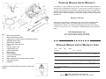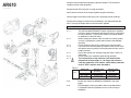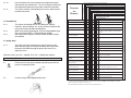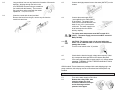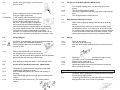
1
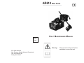
AR610 Blue Clean Place Stamp Here USE • MAINTENANCE MANUAL Warning: A.R. North America Attn: Pressure Washer Warranty Department 140 - 81st Avenue NE Fridley, MN 55432 This manual must be read before installation or use of the unit. PRESSURE WASHER LIMITED WARRANTY This product is under warranty to the original retail consumer against defects in material and workmanship for a period of 1 (one) year on machine, 90 days on gun and hose assembly, from the date of retail purchase and is not transferable. Warranty covers replacement parts. This limited one year warranty applies only to products used in consumer applications and does not apply to rental or commercial applications. WARRANTY RETURNS Items returned for warranty consideration must have a Returned Merchandise Authorization (RMA) number. All unauthorized returns will be refused and shipped back to sender. Call 1-866-815-2036 Monday through Friday 8:00 a.m. - 5:00 p.m (Central Standard Time). Or E-Mail to: [email protected] 24 hours a day. A.R. North America, Inc. Key 1 2 3 4 5 6 7 8 9 10 11 12 13 14 15 16 17 - Water outlet (OUTLET) Water inlet with filter (INLET) High pressure rotating nozzle kit (optional accessory) Adjustable spray nozzle Maintenance handbook Power supply cable with plug Lance Gun with safety catch High-pressure hose Nozzle cleaning tool Motor switch Pressure guage Pressure regulator knob Tank outlet plug Motor rotation key (for models with this feature) Detergent tank plug Data plate 140 - 81st Avenue NE • Fridley, MN 55432 Attn: Pressure Washer Warranty Department PRESSURE WASHER LIMITED WARRANTY CARD Mr. Mrs. Ms. Miss First Name: Initial: Address: (Number and Street) Apt. #: City: State: Zip/Postal code: Telephone: Date of Purchase: - Month Model Name: Replace the red transportation cap with the oil filter cap dipstick. Last Name: Day Year Purchase Price: $ .00 (excluding tax) Serial Number: Located on product package/box Store Name: All fields must be filled out for warranty. Warranty void from Manufacture if this card is not returned. Notes 1. INTRODUCTION The high pressure power-jet cleaner you have purchased is a technologically advanced product designed by one of the leading European manufactures of high-pressure pumps. To obtain the best performance from your unit, read this booklet carefully and follow the instructions each time you use the cleaner. We congratulate you on your choice and wish you successful operation. * Read and understand these instructions before operating the cleaner. Pay particular attention to the safety symbols through out this manual. Failure to comply with these instructions may result in personal injury or property damage. DO NOT allow children to operate or play on or around this equipment. * Plug the cleaner into a properly grounded 3-prong outlet. Improper grounding can result in electrical shock. 2. SAFETY RULES 2.1 2.1.1 2.1.2 2.1.3 2.1.4 2.1.5 2.1.6 2.1.7 2.1.8 2.1.9 2.1.10 Safety “MUST NOTS” DO NOT use the cleaner with flammable or toxic liquids, or any products, which are not compatible with the correct operation of the cleaner. EXPLOSION OR POISONNING HAZARD. DO NOT direct the water jet towards people or animals. INJURY HAZARD. DO NOT direct the water jet towards the unit itself, electrical parts or towards other electrical equipment. ELECTRICAL SHOCK HAZARD. DO NOT use the cleaner outdoors if raining. SHORT CIRCUIT HAZARD. DO NOT allow children or incompetent persons to use the cleaner. INJURY HAZARD. DO NOT touch the plug and/or socket with wet hands. ELECTRIC SHOCK HAZARD. DO NOT use the cleaner if the electrical cable is damaged. ELECTRIC SHOCK AND SHORT CIRCUIT HAZARD. DO NOT use the cleaner if the high-pressure hose or spray gun assembly is damaged. EXPLOSION HAZARD. DO NOT jam or lock the spray gun trigger in the operating position. ACCIDENT HAZARD. Check that the data plates are affixed to the cleaner, if not, contact your dealer. Cleaners without plates must NOT be used, as they are unidentifiable and potentially dangerous. ACCIDENT HAZARD. 2.1.11 2.1.12 2.1.13 2.1.14 2.2 2.2.1 2.2.2 Do not tamper with or alter the calibration of the safety valve. EXPLOSION HAZARD. DO NOT alter the original diameter of the spray head nozzle. OVER PRESSURIZATION MAY OCCURE. DO NOT leave the cleaner unattended. ACCIDENT HAZARD. DO NOT move the cleaner by pulling on the electrical cable. SHORT CIRCUIT HAZARD. Safety “MUSTS” All electrical circuits MUST BE PROTECTED against the water jet. SHORT CIRCUIT HAZARD. The cleaner MUST ONLY BE CONNECTED to a ground fault system. ELECTRIC SHOCK HAZARD. • Use of a safety residual current circuit-breaker (R.C.C.B.) will provide additional protection for the operator. (30 mA) 2.2.3 2.2.4 2.2.5 2.2.6 2.2.7 2.2.8 2.2.9 2.2.10 2.2.11 The high pressure may cause materials to bounce off surfaces at speeds; therefore protective clothing and safety goggles MUST BE WORN. INJURY HAZARD. Before working on the cleaner, REMOVE the electrical plug. ACCIDENTAL START UP HAZARD. Before pressing the trigger, GRIP the gun firmly to counteract the recoil. INJURY HAZARD. COMPLY WITH the requirements of the local water supply company. According to DIN 1988, power-jet cleaners may only be connected to the mains drinking water supply with a backflow preventer valve with drain facility is installed in the supply hose. CONTAMINATION HAZARD. A qualified technician MUST carry out maintenance and/or repair of the electrical components. ACCIDENT HAZARD. DISCHARGE residual pressure before disconnecting the cleaner hose. Turn the water supply off and squeeze the spray gun trigger. INJURY HAZARD. Before each use. CHECK that all the screws are fully tightened and that there are no broken or worn parts. ACCIDENT HAZARD. Only USE detergents, which will not corrode the coating materials of the high- pressure hose/electrical cable and unit components. EXPLOSION AND ELECTRIC SHOCK HAZARD. ENSURE that all people or animals keep a minimum distance of 16 yd. (15m) away. INJURY HAZARD. Pos. Code Description 22 23 24 25 26 27 28 29 30 31 32 33 34 35 36 37 38 39 40 41 42 43 44 45 46 47 48 49 50 51 52 53 54 55 56 57 58 59 60 61 1340700 1261560 1260760 1200430 1340811 1260351 390210 1342010 1342001 1343250 1340340 1340320 1260760 1260300 1340350 1269100 1340780 1340480 1263520 1263510 1263550 1341221 1263110 1341140 1265080 1261560 1262370 1463860 1463850 1260810 1340280 4380 1260780 1344060 1040710 1260050 1344050 1340050 1340300 880111 1341070 480890 111120 1341080 1340060 1340080 1340070 1260460 600180 1341010 1342740 1341020 850670 600180 1349236 1260440 770260 1342730 1342760 1342720 1342750 1349053 800560 390341 1343110 Black post. casing Screw Screw Screw Black plug Tank plug O-Ring Black ant. casing Black pres. gauge cover Cable Bearing Rear cover Screw Fan Seal Earth connection Switch-box gasket Switch box Capacitor 40μF Capacitor 32μF Capacitor 80μF Switch 8A Switch 16A Switch 8A gasket Switch 16A gasket Screw Gland Nut Gland Screw Clamp Electric motor Screw Cover O-Ring Bushing Pump body Oil level Crankshaft Key Roller bearing Circlip Circlip Seal Con-rod Pin Guiding piston Seal O-Ring Spacer Piston Washer Screw O-Ring Pump assembly Gasket O-Ring Piston guide Gasket Support ring Plate Complete valve O-Ring O-Ring O-Ring 1 2 4 8 1 1 1 1 1 1 1 1 4 1 1 1 1 1 1 1 1 1 1 1 1 4 1 1 1 1 1 1 4 1 1 1 1 1 1 1 1 1 1 1 3 3 3 3 4 3 3 3 3 1 1 3 3 3 3 3 3 6 6 1 1 62 63 64 65 66 67 68 69 70 71 72 1342710 1460430 1460260 1540140 880270 1342690 550450 1340250 1340260 2605 881470 Nozzle O-Ring Piston Spring O-Ring Outlet fitting Ring nut Hose tail Filter Suction fitting Screw 1 1 1 1 1 1 1 1 1 1 4 1 2 3 4 5 6 7 8 9 10 11 12 13 14 15 16 17 18 19 20 21 Qty. Pos. Code Description 73 74 75 76 77 78 79 80 81 82 83 84 85 86 87 88 89 90 91 92 93 94 95 96 97 98 99 100 101 680700 480480 1340190 780050 620301 1342670 851100 1250270 1250280 3225 1342700 1460430 1460150 1343810 740290 1260670 1342680 1381550 1343510 1080190 1460140 1269115 1080401 1343450 1460190 1343000 1980640 1060120 392840 Screw O-Ring Cover O-Ring Plug Pump head Grub Spring Ball Pressure gauge Regulation valve seat O-Ring Lower piston Valve seat O-Ring Detergent fitting Head cover Washer Screw O-Ring Upper piston Hose & filter Ring Spring plate Spring Spring plate Knob insert Nut Grub screw Qty. 1 3 1 1 1 1 1 1 1 1 1 1 1 3 5 1 1 4 4 1 1 1 1 1 1 1 1 1 1 102 1322520 Knob 1 Repair Kits for Pump Water Seals Valves Pistons Oil Seals Kit 2624 Kit 1880 Kit 2623 Kit 1876 Pos. Qty. Pos. Qty. 52 53 55 56 57 3 3 3 3 3 58 59 O-Rings Kit 2767 Pos. Qty. 17 22 27 34 35 37 40 49 51 60 63 69 72 2 1 3 1 1 1 1 3 1 1 5 5 1 6 6 Pos. Qty. Pos. Qty. 45 47 48 3 3 3 31 40 44 52 1 1 3 1 AR610 Always use two hands when operating a pressure washer. This will assure complete control of the equipment. Always test the GFCI plug prior to using the cleaner. Never test the pressure of the cleaner against any part of the body. Use the trigger lock whenever the spray gun is not being used for cleaning. Always seek emergency medical care immediately if any fluid penetrates the skin. A cut may be deeper and more serious than it appears. 3. GENERAL RULES 3.1.1 The USE and MAINTENANCE manual constitutes an essential part of the cleaner equipment and should be kept in a safe place for future reference. If you sell the cleaner, the manual should be handed on to the new owner. Before starting the cleaner, make sure that it is receiving water correctly. Operating the cleaner without water could damage the seals. Do not disconnect the plug by pulling on the electrical cable. If you are too far from the object you wish to clean, do not move the cleaner nearer by pulling on the high pressure hose; use the handle provided. Protect the cleaner from freezing during the winter. Store in a warm area. Do not obstruct the ventilation grilles during operation. The cross-section of any extension cord used must be proportional to their length, i.e., the longer the extension cord, the greater the cross-section; cables with a protection level of “IPX5” must be used. See table A. 3.1.2 3.1.3 3.1.4 3.1.5 3.1.6 3.1.7 Table A Voltage Volts Extension cable up to 25 m Extension cable up to 50m 220 – 230240 100 – 115120 Section3x1.5mm2 Section3x2.5mm2 Section3x2.5mm2 Section3x4mm2 Motor 3.1.8 3.1.9 Position the cleaner AS NEAR AS POSSIBLE to the water supply. The packaging is easily recyclable, and must be disposed of in compliance with the regulations in force in the country of installation. 3.1.11 Use the cleaner only with accessories and replacement parts authorized by the manufacturer. The use of original accessories and replacement parts will ensure safe, trouble-free operation. The cleaner must be used standing on a secure, stable surface, positioned as shown. The pump does not operate at the prescribed pressure. Sudden changes in pressure. Excess noise. PROBLEMS AND REMEDIES Water leakages. PROBLEM 3.1.10 Oil leaks. Motor does not start. The motor buzzes but fails to start. TSS MODELS ONLY: Motor starts even though the trigger is released. TSS MODELS ONLY: No water when lever is operated (when supply hose is connected). Power cord damage. 9 9 Water supply pressure low. 9 Air begining sucked into the system. 9 9 3.2.1 3.2.2 3.2.3 The cleaner is intended only for the cleaning of vehicles, machines, boats, buildings, etc., by the removal of stubborn dirt using clean water and chemical detergents. When using chemical detergents, only use biodegradable types. We recommend HOBBY – FOAM detergent (#3206). Only clean vehicle engines in areas in which suitable oil traps are installed. Replace nozzle. Water filter clogged. Clean filter 9 Switch off the cleaner and operate the gun until a steady flow of water is obtained. The switch cleaner back on. Adjustable nozzle incorrectly positioned. 9 Pull the spray adjuster back (+). The safety valve also functions as a pressure-limiting valve. When the gun trigger is released, the safety valve opens and the water recirculates through the pump inlet. Never try to adjust this valve. Extension cords: up to 50’ = 14AWG; 50’ to 100’ = 12AWG wire required. Water temperature too high. Nozzle clogged. CAUSES 3.3.1 Check that hose fittings are tight. Air in pump. Water suction from external tank. 3.3 Safety Valve Open the water supply tap fully. Air is being sucked in. Worn seals. Oil seals worn. No electrical power. (§) 9 99 9 9 99 9 9 Connect the power-jet cleaner to the mains water supply. Lower temperature. 9 Clean with tool provided. Check water inlet and outlet connections. Fit new seals. Fit new seals. Check that the plug is firmly in the supply socket and that main power is present. Supply voltage below required minimum. 9 Check the voltage of the main supply line. 4. INSTALLATION/ASSEMBLY Voltage loss due to use of extension cord of inadequate cross-section or excessive length. 9 Consult instructions regarding extension cords. 4.1 High pressure cleaner in disuse for extended period of time. 9 Insert the key in the hole at the rear of the electric motor and unlock. (fig 6B) - Except for the ‘extreme’ - Fit the lance into the gun by rotating and pushing until the two parts are completely locked. Sealing defects in high pressure system or water circuit. TSS faults. Nozzle is clogged. 4.2 Connect the gun to the high-pressure hose. ------------------- 9 99 9 9 Contact nearest service center. Contact nearest service center. Switch off poer. Discharge pressure. Clean nozzle. Contact nearest service center. (§) If the motor stops and fails to restart, wait 2 - 3 minutes before restarting. THERMAL CUTOUT TRIPPED. If this fault occurs more than once, contact your service center. More troubleshooting information on our website at www.arnorthamerica.com. REMEDIES 3.2 Intended Use Nozzle worn or wrong type. 6.3 Long periods of non-use may lead to the formation of lime scale deposits. Working through the hole on the rear, RELEASE the motor using a screwdriver (for models with this feature). Then remove the screwdriver and proceed with the restart operations. - Except for the Extreme - 6.4 Clean the nozzle with the tool provided. Remove the lance from the gun; remove any dirt from the nozzle hole and rinse. 4.3 Connect the high-pressure hose to the water (OUTLET) on the cleaner. 4.4 Connect the water supply hose. (not supplied) to the water (INLET) of the cleaner. The supply hose must have an internal diameter of at least 13 mm (1/2 in.) and must be reinforced. The water supply must be at least equal to the cleaner delivery capacity. The intake water temperature must NOT exceed 60° C (122°F). The water supply pressure must NOT exceed 10 BAR (145 PSI). 4.4.1 4.5 4.6 4.6.1 CAUTION! The cleaner must only be used with clean water; use of unfiltered water or corrosive chemicals will damage the cleaner. Turn the motor switch to the “0” position. Check that the electrical supply voltage and frequency (Volts/ Hz) correspond those specified on the cleaner data plate. If the motor stops and fails to restart, wait 2 to 3 minutes before restarting. THERMAL CUTOUT TRIPPED AND MUST COOL BEFORE RESTARTING. AR610 models: These cleaners are packaged with a red shipping plug in the pump crankcase, this red plug must be removed and the black dipstick cap installed. 5. USE 5.1 5.2 Turn on the water supply to FULL flow. Release the safety catch, then press the trigger for a few seconds to allow air to escape and to discharge residual pressure in the pipes. 5.3 Pull the spray gun trigger; push the switch start the motor. to 5.6 5.6.1 5.6.2 5.6.3 5.3.1 TSS Models: When re-starting the motor, always keep the spray gun trigger compressed. In TSS models, with automatic delivery flow cut-off: when the trigger is released, the dynamic pressure automatically cuts out the motor. When the trigger is compressed the pressure drop automatically starting the motor and the pressure is restored with a very slight delay. For correct operation of the TSS, once the trigger has been released it must not be pressed again for at least 4 – 5 seconds. For correct use of the TSS model cleaner, do not leave the unit in automatic cut-off status for more than 15 min. 5.6.4 5.7 5.7.1 Correct Use of the Rotary Nozzle (Where fitted) For increased washing power, use the rotary nozzle kit as follows: Turn off the high pressure cleaner. Unscrew the adjustable head and fit the rotary nozzle onto the lance. Turn the high pressure cleaner back on. Recommended Cleaning Procedure Dissolve dirt by applying detergent with the fan jet to the dry surface. On vertical surfaces, work from the bottom upwards. Leave the detergent to act for 1 to 2 minutes, but do not allow to dry out. Apply the high preesure jet, keeping the nozzle at least 10 in. from the surface, working from the bottom upwards. Avoid allowing the rinsing water to run on the unwashed surfaces. 5.4 Using Detergent 5.8 5.4.1 CAUTION: liquid detergent must be sprayed at low pressure. See 5.5 “Proper use of standard accessoreis.” Fill the detergent tank to the level indicated through the inlet. 5.8.1 5.8.2 5.8.3 Switch off the cleaner. Turn off the water supply tap. After use, the detergent residues should be removed from the tank. 5.8.4 Discharge residual pressure by pressing the trigger until no more water comes out of the adjustable nozzle. Engage the gun safety catch. Remove the plug from the socket. Operate the cleaner with non-corrosive/non-toxic antifreeze before storing for the winter. 5.4.2 5.4.3 Select LOW PRESSURE (see instructions); the detergent will be sucked up and mixed with the water, with the suction rate regulated by the knob provided. (Model not fitted with detergent control knob). 5.4.4 Now distribute the detergent drawn in and mixed with water. 5.5 Correct Use of standard accessories. (Where fitted) 5.5.1 The cleaner is equipped with the adjustable nozzle, which provides some important functions: LOW PRESSURE operation (fur suction and spraying of dtergent). HIGH PRESSURE operation (for high pressure wahsing and rinsing). Jet adjustment from pencil to fan. (For models with this feature). 5.5.2 5.5.3 5.5.4 5.8.5 5.8.6 5.8.7 6 6.1 6.2 Storage MAINTENANCE CAUTION! Before working on the cleaner, disconnect the plug from the power supply socket. To ensure good performance, check and clean the suction and detergent filters after every 50 hours of operation.