1
n
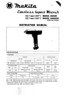
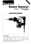
50 mm (2")
MODEL HR5000
INSTRUCTION MANUAL
DOUBLE
INSULATION
SPECIFICAT I 0NS
Capacities
50 mm
12"1
No load
speed
IRPMl
Core bit
Tungsten
carbide bit
Blows
per
minute
Overall
length
Net
weight
4 7 6 mm
( 1 8 314")
9 6 kg
(21 1 Ibs)
Hume pipe
1 5 0 mm
15 71B"I
255 mm
110")
260
2,100
Manufacturer reserves the right to change specifications without notice.
* Note: Specifications may differ from country to country.
IMPORTANT
SAFETY INSTRUCTIONS
(For All Tools)
WARNING: WHEN USING ELECTRIC TOOLS, BASIC SAFETY PRECAUTIONS SHOULD ALWAYS BE FOLLOWED TO
REDUCE THE RISK OF FIRE, ELECTRIC SHOCK, AND PERSONAL INJURY, INCLUDING THE FOLLOWING:
READ ALL INSTRUCTIONS.
1. KEEP WORK AREA CLEAN. Cluttered areas and benches invite injuries.
2. CONSIDER WORK AREA ENVIRONMENT. Don't use power tools in damp
or wet locations. Keep work area well lit. Don't expose power tools t o rain.
Don't use tool in presence of flammable liquids or gases.
3. KEEP CHILDREN AWAY. All visitors should be kept away from work area.
Don't let visitors contact tool or extension cord.
4. STORE IDLE TOOLS. When not in use, tools should be stored in dry, and high
or locked-up place - out of reach of children.
5 . DON'T FORCE TOOL. It will do the job better and safer at the rate for which
it was intended.
6. USE RIGHT TOOL. Don't force small tool or attachment t o do the job of a
heavy-duty tool. Don't use tool for purpose not intended.
7 . DRESS PROPERLY. Don't wear loose clothing or jewelry. They can be caught
in moving parts. Rubber gloves and non-skid footwear are recommended
when working outdoors. Wear protective hair covering t o contain long hair.
8. USE SAFETY GLASSES. Also use face or dust mask if cutting operation is
dusty.
9. DON'T ABUSE CORD. Never carry tool by cord or yank it t o disconnect from
receptacle. Keep cord from heat, oil, and sharp edges.
IO. SECURE WORK. Use clamps or a vise t o hold work. It's safer than using
your hand and it frees both hands t o operate tool.
11. DON'T OVERREACH. Keep proper footing and balance at all times.
12. MAINTAIN TOOLS WITH CARE. Keep tools sharp and clean for better and
safer performance. Follow instructions for lubricating and changing accessories. Inspect tool cords periodically and if damaged, have repaired by authorized service facility. Inspect extension cords periodically and replace if
damaged. Keep handles dry, clean, and free from oil and grease.
13. DISCONNECT TOOLS. When not in use, before servicing, and when changing accessories, such as blades, bits, cutters.
2
14. REMOVE ADJUSTING KEYS AND WRENCHES. Form habit of checking t o
see that keys and adjusting wrenches are removed from tool before turning
it on.
15. AVOID UNINTENTIONALSTARTING. Don’t carry plugged-in tool with finger
on switch. Be sure switch is OFF when plugging in.
16. OUTDOOR USE EXTENSION CORDS. When tool is used outdoors, use only
extension cords intended for use outdoors and so marked.
17. STAY ALERT. Watch what you are doing, use common sense. Don’t operate
tool when you are tired.
18. CHECK DAMAGED PARTS. Before further use of the tool, a guard or other
part that is damaged should be carefully checked t o determine that it will
operate properly and perform its intended function. Check for alignment of
moving parts, binding of moving parts, breakage of parts, mounting, and any
other conditions that may affect its operation. A guard or other part that
is damaged should be properly repaired or replaced by an authorized service center unless otherwise indicated elsewhere in this instruction manual.
Have defective switches replaced by authorized service center. Don‘t use
tool if switch does not turn it on and off.
19. GUARD AGAINST ELECTRIC SHOCK. Prevent body contact with grounded
surfaces. For example; pipes, radiators, ranges, refrigerator enclosures.
20. REPLACEMENT PARTS. When servicing, use only identical replacement parts.
VOLTAGE WARNING: Before connecting the tool t o a power source (receptacle,
outlet, etc.) be sure the voltage supplied is the same as that specified on the
nameplate of the tool. A power source with voltage greater than that specified
for the tool can result in SERIOUS INJURY t o the user - as well as damage t o
the tool. If in doubt, DO NOT PLUG IN THE TOOL. Using a power source with
voltage less than the nameplate rating is harmful t o the motor.
3
ADDITIONAL SAFETY RULES
1. Wear a hard hat (safety helmet), safety glasses and/or face shield. It is also
highly recommended that you wear a dust mask, ear protectors and thickly
padded gloves.
2. Be sure the bit is secured in place before operation.
3. Under normal operation, the tool is designed t o produce vibration. The screws
can come loose easily, causing a breakdown or accident. Check tightness
of screws carefully before operation.
4. In cold weather or when the tool has not been used for a long time, let the
tool warm up for several minutes by operating it under no load. This will loosen up the lubrication. Without proper warm-up, hammering operation is
difficult.
5. Always be sure you have a firm footing.
Be sure no one is below when using the tool in high locations.
6.
7.
8.
9.
Hold the tool firmly with both hands.
Keep hands away from moving parts.
Do not leave the tool running. Operate the tool only when hand-held.
Do not point the tool at any one in the area when operating. The bit could
fly out and injure someone seriously.
IO. When drilling or chipping into walls, floors or wherever "live" electrical wires
may be encountered, DO NOT TOUCH ANY METAL PARTS OF THE TOOL!
Hold the tool by the insulated grasping surfaces t o prevent electric shock
if you drill or chip into a "live" wire.
11. Do not touch the bit or parts close t o the bit immediately after operation;
they may be extremely hot and could burn your skin.
SAVE THESE INSTRUCTIONS.
4
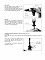
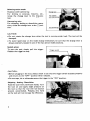
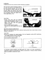
Side handle
The side handle can be secured in four
positions (right, left, up and down).
To secure the side handle, tighten the wing
nut securely. Never secure the side handle
in other than the above four positions.
Side grip
The side grip i s convenient for downward
drilling or chipping operations. Screw the
side grip on the tool securely. The side grip
can be installed on either side of the tool
for right or left hand operation.
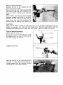
Installing or removing drill bit or other bits (bull point, etc.)
CAUTION:
Always be sure that the tool is switched off and unplugged before installing or removing
the bit.
Insert the bit into the tool holder as far
as it will go, Pull out and turn the tool
retainer 180 degrees. Then release it to
secure the bit.
To remove the bit, follow the installation
procedure in reverse.
5
Selecting action mode
Rotation with hammering:
For drilling in concrete, masonry, etc.,
rotate the change lever to the
position.
Hammering only:
For chipping, scaling or demolition operapositions, rotate the change lever to the
tion.
?
CAUTION :
.Do not rotate the change lever when the tool is running under load. The tool will be
damaged.
.To avoid rapid wear on the mode change mechanism, be sure that the change lever is
always positively located in one of the two action mode positions.
Switch action
To start the tool, simply pull the trigger.
Release the trigger to stop.
Trigger switch
CAUTION:
0 Before plugging in the tool, always check to see that the trigger switch actuates properly
and returns to the "OFF" position when released.
0
Do not tape, t i e or otherwise secure the trigger in the "ON" position.
-
-
Chipping Scaling Demolition
Hold the tool firmly with both hands. Turn
the tool on and apply slight pressure on
the tool so that the tool will not bounce
around, uncontrolled. Pressing very hard
on the tool will not increase the efficiency.
6
Hammer drilling operation
Position the bit a t the location for the
hole, then pull the trigger.
Do not force the tool. Light pressure gives
best results. Keep the tool in position and
prevent it from slipping away from the
hole.
Do not apply more pressure when the hole
becomes clogged with chips or particles.
Instead, run the tool a t an idle, then remove from the hole. By repeating this
several times, the hole will be cleaned out.
CAUTION :
When the bit begins to break through concrete or if the bit strikes reinforcing rods embedded in concrete, the tool may react dangerously. Maintain good balance and safe
footing while holding the tool firmly with both hands to prevent dangerous reaction.
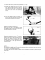
Core bit (optional accessory)
[When using the center bit]
Screw the core bit on the adapter. Install
the adapter with t h e core bit in the tool in
the same manner as a drill bit.
Install the center bit.
Rest the core bit on the concrete and turn
the tool on. Once the core bit has cut a
shallow groove into the concrete, remove
the center bit. Then resume drilling.
7
To remove the core bit, follow the procedures ( 1 ) or (2).
1) Rotate the change lever to the position. Then rest the core bit on the concrete and turn the tool on. The core bit
will come loose from the hammering
action.
2) Hold the adapter with the wrench, insert the rod into the hole in the core bit
and tap with a hammer to unscrew.
[When not using the center b i t ]
Screw the core bit on the adapter. Install
the adapter with the core bit in the tool in
the same manner as a drill bit.
Rotate the change lever to the
position.
Rest the core bit on the concrete and turn
the tool on. Once the core bit has cut a
shallow groove into the concrete, rotate
the change lever to the
position and
resume drilling.
Ti
NOTE :
No problem i s caused even if the core bit unscrews slightly during brief use since the core
bit rotates in the tightening direction.
To remove the core bit, follow the same removal procedures covered in [when using the
center bit 1.
8
MAINTENANCE
CAUTION:
Always be sure that the tool is switched off and unplugged before attempting to perform
inspection or maintenance.
Replacing carbon brushes
When the resin insulating tip inside the
carbon brush is exposed to contact the
commutator, it will automatically shut off
the motor.
When this occurs, both carbon brushes
should be replaced a t the same time. Use
only Makita carbon brushes.
I
Insulating t i p
>I--
1'
Carbon brush
Use a hex wrench to remove the rear cover.
Use a screwdriver to remove the brush
holder caps. Take out the worn carbon
brushes, insert the new ones and secure the
brush holder caps.
9
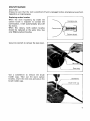
Lubrication
Lubricate the tool every time the carbon brushes are replaced.
Run the tool for several minutes to warm it
up, then rest the tool on the table with the
bit end pointing upwards. This will allow
the old grease to collect inside the crank
housing. After five minutes, take off the
crank cap and remove the old grease. Wipe
out all grease inside and replace with a
fresh supply (30 g; 1 oz).
CAUTION :
Filling with more than the specified
amount of grease (approx. 309; 1 oz.) can
cause faulty hammering action or tool
failure. Fill only with the specified
amount of grease.
0
0
Use only Makita genuine grease.
The use of any other grease may harm the
tool.
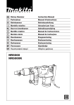
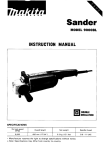
Sharpening tungstencarbidetip bit
When your bit becomes dull, use an ordinary bench grinder with a wheel made of silicon
carbide to resharpen it.
CAUT I0N :
.Be sure to maintain the original angles of the tip. Especially without 60" chamfering,
the tungsten-carbide tip may be damaged.
Do not quench the bit in water or oil.
0 Do not grind the sides B and C.
0
To maintain product SAFETY and RELlABl LITY, repairs, any other maintenance or
adjustment should be performed by Makita Authorized or Factory Service Centers,
always using Makita replacement parts.
10
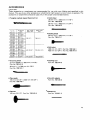
ACCESSORIES
CAUTION :
These accessories or attachments are recommended for use with your Makita tool specified in this
manual. The use of any other accessoreis or attachments might present a risk of injury t o eprsons. The
accessories or attachments should be used only in the proper and intended manner.
0
Tungsten-carbide tipped (hammer) bit
0
Cold chisel
26 mm (1") x 300 mm (11-7/8")
Part No. 798139-8
26 m m (1") x 450 mm (17-3/4")
Part No. 798140-3
Ovsrall length
Imml
0
Scaling chisel
50 m m (2") x 300 mm (11-7/8")
Part No. 798141-1
0
Bull point
300 mm (1 1-7/8") Part No. 798146-1
450 mm (17-3/4") Part No. 798147-9
0
Bushing tool
Part No. 798144-5
380 (1 5'1
525 120-11/16")
700 127-9/16"1
0
Grooving chisel
22 mm (55/64") x 300 mm (1 1-7/8")
Part No 798142-9
26 mm (1") x 300 mm (11-7/8")
Part No. 798143-7
0
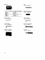
Clay spade
105 mm (4-1/8") x 400 mm (15-3/4")
Part No. 798148-7
0
Rammer
140 mm (5-1/2") Part No. 798149-6
0 Core
bit adapter
Part No. 798138-0
Center b i t
Part No. 752027-3
11
Core bit
0
Rod
Part No. 256815-5
H~~~~~ grease 30 cc
Part No. 181490-7
0
Hex wrench 4
Part No. 783202-0
0
0
Hex wrench 6
0
Steel carrying case
Part No. 181997-3
12
Lock nut wrench 3 5
Part No. 782407-9
Part No. 783204-6
0
Hex wrench 5
Part No. 783203-8
0
Grip 3 2
Part No. 273472-4
Sep-084l8
@7hnKitrr
EN
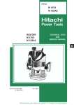
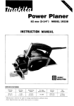
50 m m (2")
ROTARY HAMMER
Model HR5000
Note: The switch, noise suppressor and other part configurations
may differ from country to country.
13
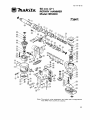
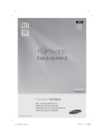
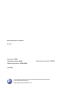
MODEL HR5000
{2D
O
'M
;'
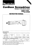
DESCRIPTION
MACHINE
1
2
3
4
5
6
7
8
9
10
11
12
13
14
15
16
17
18
19
20
21
22
23
24
25
26
27
28
29
30
31
32
33
34
35
36
37
38
39
40
41
42
43
44
45
46
47
48
49
50
51
52
53
54
55
56
57
58
3
1
1
1
1
1
1
1
1
1
1
1
1
1
1
1
1
1
2
1
1
1
1
1
1
1
1
1
1
1
1
1
1
1
1
1
1
1
1
1
1
1
1
1
1
1
1
1
2
2
1
1
2
1
1
1
1
1
-
Key 4
Barrel
0 Ring 65
Plans Bearing 52
FIal Washer 52
Spiral Bevel Gear 41
Strickar
Ptnon Ring 40
Inner Ring 36
Piston Ring 40
Inner Ring 36
P m 10
Piston
Crank Cap
0 Ring 71
Connecting Rod
Needle Bearing 1516
Crank Shaft
Woodrulf Key 4
Woodrut1 Key 4
Retaining Ring R-52
Ball Bearing 6304
0 Ring 53
Crank Housing
Helical Gear 41
Spur Gear 24
Needle Bearing 1212
Rubbar Pm 6
ORing 114
Gear Housing
FIal Washer 16
Ball Bearing 638
Flat Washer 8
Comprssaon Spring 12
Torgua Limiter
Thin Washer 10
Gear
Needle Bearing 2216
Needle Bsanng 609
Stop Ring E-4
0 Ring 10
Change Shaft
PIPB
Steal Ball 4.0
Compresslo" sprmg 3
Change Lever
Flat Washer 4
Hex. Socket Head Bolt M 4 x l 6 [With Washerl
Spring Washer 5
Hex. Socket Head Bolt M5x12
lmpacr Bolt
Flat Washer 43
Ball Bearing 6907
Hex. Nu1 M34.8-41
X Ring 28
0 Ring 27
0 Ring 55
Tool Retainer
59
60
61
62
63
64
65
66
67
68
69
1
1
1
1
4
1
1
1
1
1
1
70
71
72
73
74
75
76
77
78
79
60
81
82
83
64
85
86
87
88
89
90
91
92
93
94
95
96
97
98
99
100
101
102
103
104
105
108
109
110
111
112
113
114
115
116
1
1
1
2
2
1
4
1
1
2
2
1
2
2
4
4
1
1
1
1
1
1
1
1
2
2
2
2
2
1
1
1
1
1
1
1
1
1
1
1
1
1
2
1
2
-
-
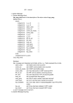
Note: The switch and other p a n specifications may differ from country to country.
14
Tool Holder
Compression Spring 15
Flat Washer 8
Hex. Nut M8
Hex. Socket Head Bolt M8x30 (With Washer]
Cylinder Liner 40
0 Ring 32
Ball Bearing 6201
011
Seal 14
Fan 94
ARMATURE ASSEMBLY
[With Item 68 - 711
Insulation Washer
Ball Bearing 6200VV
0 Ring 30
Hex. Bolt M5x55
Lock Washer 5
FIELD ASSEMBLY
Rwet 0 - 5
Name Plate
Motor Housing
Brush Holder Cap
Carbon Brush
Rear Cover
Spring Washer 5
Hex. Socket Head Bolt M5x16
Hex. Socket Head Boll M6x55
Flat Washer 6
Rubber Sheet
Split Pin 3.0-20
Side Handle
Wing Nut M10
Spring Washer 10
Set 8011 M10x20
Split Pin 3.0-20
Grip 38
Hex. Socket Head Bolt M 6 x l 4
Spring Washer 6
Cushion Plate
Hex. Socket Head Bolt M 6 x l 4
Spring Washer 6
Dust Cover
Pan Head Screw M4x16 [With Washer)
Switch
Hex. Nut M6
Spring Washer 6
Flat Washer 6
Rubber Pin 4
Rubber Pin 4
Handle Shalt
Handle Set IWith Item 115)
Cord Guard
Cord
Strain Relief
Pan Head Screw M4x18 lWnh Washer1
Handle Set IWith Item 1101
Pan Head Screw M5x25 (With Washer)
MAKKA LIMED ONE YEAR WARRANTY
Warranty Policy
Every Makita tool is thoroughly inspected and tested before leaving the factory. It is warranted to
be free of defects from workmanship and materials for the period of ONE YEAR from the date of
original purchase. Should any trouble develop during this one-year period, retum the COMPLETE
tool, freight prepaid, to one of Makita’s Factory or Authorized Service Centers. If inspection shows
the trouble is caused by defective workmanship or material, Makita will repair (or at our option,
replace) without charge.
This Warranty does not apply where:
repam have been made 01 attempted by others.
repairs are required because of normal wear and tear
The tool has been abused. misused 01 improperly mamtained;
alterations have been made to the tool.
IN NO EVENT SHALL MAKITA BE LIABLE FOR ANY INDIRECT, INCIDENTAL OR CONSEQUENTIAL DAMAGES FROM THE SALE OR USE OF THE PRODUCT. THIS DISCLAIMER
APPLIES BOTH DURING AND AFTER THE TERM OF THIS WARRANTY.
MAKITA DISCLAIMS LIABILITY FOR ANY IMPLIED WARRANTIES, INCLUDING IMPLIED
WARRANTIES OF “MERCHANTABILITY” AND “FITNESS FOR A SPECIFIC PURPOSE,”
AFTER THE ONE-YEAR TERM O F THIS WARRANTY.
This Warranty gives you specific IegaI rights, and you may also have other rights which vary from
state to state. Some states do not allow the exclusion or Limitation of incidental or consequential
damages, so the above limitation or exclusion may not apply to you. Some states do not allow
limitation on how long an implied warranty lasts, so the above limitation may not apply to you.
Buford, GA
883643 - 998
P R I N T E D IN J A P A N
1989- 11 - N