1
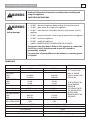
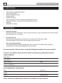
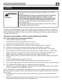
Heating A Division of A.F. Gason Pty Ltd Jindara Derwent High Efficiency Gas Log Fire Operation & Installation Instructions REV. B SERIAL NO. 221300- GPN 221324 Derwent High Efficiency Gas Log Fire 2 Contents Warnings and name plate details ...............................................................................................................................................3 Product features and safety features ..........................................................................................................................................4 Installation....................................................................................................................................................................................5 Heater installation overview.........................................................................................................................................5 Removing the door assembly.......................................................................................................................................6 Installing the logset ......................................................................................................................................................6 Clearance dimensions...................................................................................................................................................7 False fireplace construction ..........................................................................................................................................7 Vertical chimney flue installation .................................................................................................................................8 Horizontal flue installation ...........................................................................................................................................9 Horizontal flue installation (stump floor)...................................................................................................................10 Installation into a false fireplace................................................................................................................................11 Operating your Eureka Star .......................................................................................................................................................12 Pre-operation checks ..................................................................................................................................................12 Turning the appliance on............................................................................................................................................12 Turning the appliance off............................................................................................................................................12 RF Thermostat ............................................................................................................................................................................13 Features.......................................................................................................................................................................13 LCD display indications...............................................................................................................................................14 Button functions .........................................................................................................................................................15 Initial set up ................................................................................................................................................................16 Programming ..............................................................................................................................................................18 Receiver/Controller......................................................................................................................................................21 Quick reference table..................................................................................................................................................23 Troubleshooting ..........................................................................................................................................................24 Safety precautions and general care.........................................................................................................................................25 Maintenance ..............................................................................................................................................................................26 Removing the fascia panels .......................................................................................................................................26 Removing the fan .......................................................................................................................................................26 Changing the injectors................................................................................................................................................27 Adjusting gas pressure ...............................................................................................................................................27 Removing component tray.........................................................................................................................................28 Troubleshooting..........................................................................................................................................................................29 Wiring diagram ..........................................................................................................................................................................31 Dimensions.................................................................................................................................................................................32 Parts List .....................................................................................................................................................................................33 Warranty details.........................................................................................................................................................................35 Derwent High Efficiency Gas Log Fire ! WARNING ! WARNING Safety Warnings 3 Read and follow these instructions carefully before installing and using this appliance. SAVE THESE INSTRUCTIONS • DO NOT – operate this appliance before reading this instruction manual. • DO NOT – place articles on or against this appliance. • DO NOT – store chemicals, flammable materials or spray aerosols near this appliance • DO NOT – operate with panels, covers or guards removed from this appliance. • DO NOT – enclose this appliance • DO NOT – modify this applicance • ALWAYS SUPERVISE YOUNG CHILDREN NEAR THE APPLIANCE. The guard in the glass door is fitted to this appliance to reduce the risk of fire or injury from burns and no part of it should be permanently removed. For protection of young children or the infirmed, a secondary guard is required. NAME PLATE GAS TYPE NATURAL Inbuilt MODEL TYPE GAS INPUT HIGH 38.0 MJ/h LOW 20.0 MJ/h HEAT OUTPUT HIGH 9.5 kW LOW 4.3 kW Efficiency 86.5 % Injector Size Front Ø 2.15 mm Injector Size Rear Ø 2.60 mm Test Point Pressure High 0.65 kPa Low 0.16 kPa A.G.A Approval No to Code AS4553 7494 Electrical Conform to AS3100 Air Pressure Switch Cut in Pressure Cut out Pressure Electrical Connection Manufacturer PROPANE Inbuilt 38.0 MJ/h 19.0 MJ/h 9.5 kW 4.3 kW 86.5 % Ø 1.25 mm Ø 1.65 mm 1.55 kPa 0.40 kPa A. F. Gason Pty Ltd Blake St, ARARAT Victoria, Australia 3377 P.O. Box 268 TO BE INSTALLED BY AN AUTHORISED PERSON IN ACCORDANCE WITH GAS INSTALLATION INSTRUCTIONS PROVIDED WITH THIS APPLIANCE. 7494 240V 50 Hz 106 Watts Max Cleveland NSZ Series 130 Pa 120 Pa Standard Flex. 2 m, 3 pin plug Derwent High Efficiency Gas Log Fire 4 Product Features • • • • • • • • • Zero Clearance to Combustible Materials 5.05 Star Energy Rating Manual or thermostat controls Electronic ignition Variable heat settings External combustion air intake - prevents de-oxygenation of room air. Delayed start room fan - prevents cold air being circulated at start-up. Power flue. Modulated heat settings Safety Features • Automatic Pre-purge Before heater ignition this operation is done to evacuate any remains of gas or flue products from inside the firebox that could be the cause of a mishap. • Automatic Shut-off Should the flame extinguish for any reason there is an automatic shut off of the gas supply. If the power supply is cut off, the gas valve cuts supply of gas to the burners. • Over temperature protection In the event of the room fan failing , blockage of airways or incorrect gas installation, the gas supply will automatically shut off to prevent the appliance from over-heating . For your own future reference, please record the following information in the spaces provided. If you have any enquires, please contact the dealer from whom you purchased your heater: PLEASE COMPLETE: Dealer Name Dealer Address Date of Purchase Phone Serial No. of Applicance TO BE COMPLETED BY THE INSTALLER: Name Licence No. Address Phone Installation Date Please attach your original purchase dockets to this booklet for future reference. Derwent High Efficiency Gas Log Fire 5 Installation ! WARNING Installation THE INSTALLATION OF THIS APPLIANCE MUST BE CARRIED OUT AS PER THIS MANUAL. WE RECOMMEND THAT YOU USE A QUALIFIED INSTALLER TO CARRY OUT THE INSTALLATION IN ACCORDANCE WITH AS 5601/AG 601 (GAS INSTALLATION CODE), MANUFACTURER’S INSTALLATION INSTRUCTIONS, LOCAL GAS FITTING REGULATIONS AND MUNICIPAL BUILDING CODES. If you have any other enquiries, please contact the dealer from whom you purchased your heater. THIS APPLIANCE PANEL WEIGHT IS 59 KILOGRAMS. EXTREME CARE SHOULD BE TAKEN WHEN HANDLING THE APPLIANCE. The Jindara Derwent Inbuilt Heater is a zero clearance appliance and can be optionally installed in a false fireplace or wall cavity made of combustible materials such as wood or chipboard. Jindara provide the heater with their own flue kit, of flexible pipes of 60mm and 50mm diameter for the inlet and exhaust. For the gas supply a flexible hose is provided and must be used. HEATER INSTALLATION OVERVIEW - REFER TO 10 POINT COMMISSIONING CHECKLIST ONLY TO BE CARRIED OUT BY AN AUTHORISED PERSON! 1. Carefully remove the carton from the heater. 2. Carefully unpack flue kit and logset (positioned at rear of heater.) 3. Remove heater from pallet by undoing 3 x teck screws on sides and rear. (a) Remove the 2 screws holding lower fascia panel to the heater surround. (Refer Figure 1 on page 6.) (b) Disconnect connector from rear of controls and remove lower fascia. (Refer Figure 2 on page 26.) (c) Remove the 4 screws holding door assembly to the heater. Remove the door. (Refer Figures 2 & 3 on page 6.) 4. Check the label on the inside of lower fascia panel to confirm gas type is appropriate for the gas supply available. 5. Unpack the log set from its separate carton and ensure all components are undamaged and complete as per diagrams. Position them in the firebox as per diagrams. (Refer to the diagrams on pages 6 & 7.) 6. Replace the door assembly as per reverse of removal. Ensure arrows on door tabs are facing bottom. (Refer Figure 9 on page 7) 7. Install the flue (Refer to diagrams on pages 8, 9,10 &11). 8. Locate the heater body into the fireplace cavity, or pre-built wall cavity. (Refer to pages 8, 9,10 &11) 9. Connect the gas supply, purge gas lines, check all connections for leaks, check pressures (Refer to diagram on page 27) 10. Fix the appliance firmly in position using the 2 angle brackets fixed to the heater body. 11. Connect the air inlet and exhaust flexible pipes to the outlets on the heater body. (Refer to diagram on next pages 8, 9,10 &11.) Use clamps to secure flexible pipes to outlets. NOTE – The EXHAUST flue is colour coded RED at the heater body, both ends of the flexible flue pipe and at the collector box on the flue terminal assembly. Both ends of both flexitubes may need to be expanded to allow clamps to firmly secure tubes to outlets. 12. Re-assemble heater in reverse order of above. Connect electrical cord to correctly wired and earthed 240 Volt AC power point. 13. Operate heater, check operation on both, Hi and Low settings. Ensure fan operates after initial warm-up period. (Refer to the Trouble Shooting Guide on page 29 should any problems occur.) Derwent High Efficiency Gas Log Fire 6 Installation (Continued) REMOVING THE DOOR ASSEMBLY Figure (1). Remove screws from lower fascia panel at either end. Place panel carefully aside so as not to scratch or damage panel. Figure (2). Remove screws from bottom of door assembly... Figure (3). ...and top of door assembly. INSTALLING THE LOGSET - TAKE EXTREME CARE - FRAGILE! Logset components 2 pins Front Log Cross Ignitor Tube (Fixed to front log) Back Log Cross Log Figure (4). Remove the door assembly. Left twig Right twig Figure (1). Check to ensure ignitor tube is through the hole in the front log as shown. Figure (2). Place back log in position. Figure (3). Igniters fit into cutouts in logs as shown. Figure (4). Place front log in position. Figure (5). Place cross log in position by locating the lugs as shown. Figure (6). Insert pins as shown through cross log into front and rear logs. Derwent High Efficiency Gas Log Fire Installation 7 (Continued) INSTALLING THE LOGSET (continued) Figure (7). Place right twig in position. CLEARANCE DIMENSIONS Figure (9). Replace the door assembly and secure the four screws. Ensure arrows point downwards, that are on the mounting point of the door frame. Figure (8). Place left twig in position. FALSE FIREPLACE CONSTRUCTION (ZERO CLEARANCE) WIDTH 820mm min DEPTH 460mm min HEIGHT 680mm min (B) HEIGHT 680mm min DEPTH Existing Fireplace 460mm min HEIGHT 680mm min (A) WIDTH 820mm min Heater can be installed at floor level (A), or above floor level (B). Derwent High Efficiency Gas Log Fire 8 Installation (Continued) VERTICAL CHIMNEY FLUE INSTALLATION Jindara AGA Approved gas cowl (Supplied by Jindara) Gas Cowl Hose clamps (Supplied) Flue Brackets (Supplied) Flashing (Not supplied) Flue weather shield (Supplied) 4.6 metres max. 50mm exhaust flexi tube (Supplied) 60mm air intake flexi tube (Supplied) 1/2˝ copper pipe Installation into an existing fireplace (Vertical Flue Unit) 1. Connect gas cowl to flexible tubes. The 50mm dia. flexible exhaust tube and the exhaust port at the flue gas cowl are colour-coded red. Clamp 50mm dia. exhaust flexible tube and 60mm dia. air intake flexible tube to the flue gas cowl using hose clamps (supplied). (Refer detail above.) Note: Expand both ends of both flexitubes to allow clamps to firmly secure tubes to outlets. 2. Insert flue gas cowl and attached flexible tubes into weather shield, ensuring the flue gas cowl rests against the weather shield end. Slide the weather shield over the flue pipe. (Refer detail above.) Affix brackets (x3) to flue gas cowl and weather shield with rivets supplied (x6). 3. Insert flue assembly into chimney cavity (flexible tubes may need to be expanded to extend to fireplace). Ensure flexible tubes are free of obstruction. 4. Fix flue weather shield securely to top of chimney and seal to prevent water entry. Seal with high temperature waterproof sealant prior to cementing to chimney top. 5. Connect 50mm dia. exhaust flexible tube to exhaust terminal on heater body (colour-coded red) and clamp using hose clamp - smaller diameter (supplied). Connect 60mm dia. flexible tube to remaining heater body terminal using larger diameter hose clamp. Derwent High Efficiency Gas Log Fire Installation 9 (Continued) HORIZONTAL FLUE INSTALLATION False fireplace Hose clamps (Supplied) Flexi tubes (Supplied by Jindara) Jindara AGA Approved gas cowl (Supplied by Jindara) 1/2˝ copper pipe Rear vent balanced flue installation 1. Determine the exact location for the heater 2. Mark the exact location for the wall penetration a. Determine that you will not be cutting through any vertical wall studs. b. Check that the location of the wall mounted terminal conforms to the requirements of AG601 – Location of a Flue Terminal. 3. Cut 2 holes through the wall 55mm and 65mm diameter, with centres located 70mm apart. 4. Fit the 60mm Diam and 50mm dia. flexible tube to terminals on the rear of the heater using provided hose clamps. 50mm dia. flexible tube and exhaust terminal on rear of heater are colour-coded red. (NOTE- it may be necessary to trim the flexible tubes depending on wall thickness.) Note: Expand both ends of both flexitubes to allow clamps to firmly secure tubes to outlets. 5. Extend flexible tubes to allow room for fitment of tubes and hose clamps to flue gas cowl. Attach 50mm dia. exhaust flexible tube to exhaust port at flue gas cowl (both colour-coded red) and clamp using smaller diameter hose clamp. (Refer detail above.) Attach 60mm dia flexible tube to remaining terminals on heater and flue cowl then clamp using remaining larger diameter hose clamp. 6. Fix flue gas cowl to wall using suitable screws or fixtures. Seal to wall using high temperature waterproof sealant. Derwent High Efficiency Gas Log Fire 10 Installation (Continued) HORIZONTAL FLUE INSTALLATION Flexi tubes (Supplied by Jindara) Eureka AGA Approved gas cowl (Supplied by Jindara) MAX OVERALL FLUE PIPE LENGTH 4.6M Min. flue slope 25mm per metre. Use hangers every 500mm to avoid water trap. 1/2˝ copper pipe Installation on stump floor and internal wall. (Flue kit under floor.) 1. Mark the exact location for the wall penetration a. Determine that you will not be cutting through any vertical wall studs. b. Check that the location of the wall mounted terminal conforms to the requirements of AG601 – Location of a Flue Terminal. 2. Cut 2 holes through the wall 55mm and 65mm diameter, with centres located 70mm apart. 3. Fit the 60mm Diam and 50mm dia. flexible tube to terminals on the rear of the heater using provided hose clamps. 50mm dia. flexible tube and exhaust terminal on rear of heater are colour-coded red. (NOTE- it may be necessary to trim the flexible tubes depending on wall thickness.) Note: Expand both ends of both flexitubes to allow clamps to firmly secure tubes to outlets. 4. Extend flexible tubes to allow room for fitment of tubes and hose clamps to flue gas cowl. Attach 50mm dia. exhaust flexible tube to exhaust port at flue gas cowl (both colour-coded red) and clamp using smaller diameter hose clamp. (Refer detail above.) Attach 60mm dia flexible tube to remaining terminals on heater and flue cowl then clamp using remaining larger diameter hose clamp. 5. Ensure a minimum flue slope of 25mm per metre. Use hanger every 500mm to avoid water trap. 6. Fix flue gas cowl to wall using suitable screws or fixtures. Seal to wall using high temperature waterproof sealant. Derwent High Efficiency Gas Log Fire Installation 11 (Continued) INSTALLATION INTO A FALSE FIREPLACE Jindara AGA Approved gas cowl (Supplied by Jindara) See detail B Weather seal flashing (Not supplied) Flue Pipe (Supplied) See detail A 1/8˝ pop rivet (x4) Flue pipe Flue pipe support brackets Flexi tubes (Supplied by Jindara) Suitable nail or screw (x4) False fireplace Bottom of roof truss Detail A Flue gas cowl 1/8˝ pop rivet (x6) Flue cowl bracket (x3) Flue pipe 1/2˝ copper pipe Detail B False fireplace (Thru roof flue kit) NOTE: Refer to false fireplace construction illustration on page 6. 1. Determine the exact location for the flue pipe. Note: Flue support brackets must be attached to ceiling trusses. (Refer detail A above.) 2. Cut 165mm dia. hole in roof and ceiling. Insert flue pipe to desired height and affix flue support brackets (supplied) to roof truss bottom beams and flue pipe. 3. Connect flue gas cowl to flexible tubes. 50mm dia. flexible exhaust tube and exhaust port at flue gas cowl are colour-coded red. Using hose clamps provided, clamp 50mm dia. flexible exhaust tube and the 60mm dia. flexible tube to the gas cowl. Note: Before installing the flue gas cowl into flue pipe, a suitable weathershield should be attached to exterior of flue pipe and roof. Note: Expand both ends of both flexitubes to allow clamps to firmly secure tubes to outlets. 4. Insert flue gas cowl with attached flexible tubes into 6 inch flue pipe and secure flue gas cowl to flue pipe using brackets (x3) and rivets (x6) supplied. (Refer detail B above.) 5. Connect 50mm dia. exhaust flexible tube to exhaust terminal on heater body (colour-coded red) and clamp using hose clamp - smaller diameter (supplied). Clamp 60mm dia. flexible tube to remaining heater body terminal using larger diameter hose clamp. Derwent High Efficiency Gas Log Fire 12 Operating your Jindara Derwent ! WARNING Read these instructions DO NOT ATTEMPT TO OPERATE THIS APPLIANCE WITHOUT READING AND UNDERSTANDING THESE OPERATING INSTRUCTIONS THOROUGHLY. FAILURE TO OPERATE THIS APPLIANCE PROPERLY MAY CAUSE UNDUE DAMAGE TO THE APPLIANCE. The Jindara Derwent Gas log space Heater has been designed for simple operation to provide you with the highest heat output. Fan Fan PRE-OPERATION CHECKS speed speed Heat Prior to operating the heater, ensure that the flue terminal is not obstructed. Furthermore, make sure there are no combustible objects leaning against, resting on, or within the immediate vicinity of the unit. Check that the heater‘s main power and gas supply are connected and switched on. LED indicators setting setting buttons buttons OPERATING THE HEATER The heater can be operated by two different modes, manually or by the thermostat remote controlled hand held device . Manual mode: The controls are located on the right hand side of the front lower false panel. The operation of the buttons are as follows: TURNING THE APPLIANCE ON (MANUAL MODE) On/Off Button 1. To ignite your heater press the Ignition ON/OFF Button and the heater will automatically start the ignition sequence. After approximated 30 seconds of pre-purge the heater will ignite. 2. The heater will always start in the low heat setting and the heater will warm-up for at least 2 minutes before automatically going to the higher flame setting. 3. The fan will not start until the heater’s firebox has reached the minimum operating temperature. In High heat setting the fan speed will be locked in high and can not be set to medium or low speed, unless the heat setting is changed to medium or low. (This prevents overheating the heat exchanger.) NOTE: Turning on the thermostat remote will override the manual operation of the heater! To go back to manual operation of the heater, the thermostat remote needs to be off for 20 minutes before the control module will not look for any more signals from the thermostat. TURNING THE APPLIANCE OFF Press the ON/OFF switch once. The room fan will continue to operate for a short period while the heater cools down. Please note: 1. This appliance cannot be operated without the fan running. 2. Due to the performance and efficiency of the heater, steam may be noticed coming from the flue terminal on cool days. 3. As this appliance has a luminous effect some slight carbon deposition may occur. 4. During first time firing of this appliance, an odour may be noticed for a short period of time while the paint cures. It is advisable to leave the windows open during the first few hours of the very first operation only. Derwent High Efficiency Gas Log Fire 13 RF Thermostat FEATURES • • • • Backlit Liquid Crystal Display Seven Function Keyboard Four Individual Programs per Day UHF Radio Frequency LCD DISPLAY FEATURES • • • • • • • Battery type: 2 x AA batteries • • Battery Life: approximately 12 months Transmission frequency: 433.92 MHz Dimensions: 140mm x 80mm x 20mm • • Time of day with AM or PM display; Day of the week; Temperature with ROOM or SET display; System status indicator; Transmit indicator; Battery low indicator; Programming mode indicator; Manual mode indicator; Automatic mode indicator; Flame indicator; Fan indicator INITIAL DISPLAY The display when the thermostat is initially turned on or when batteries are replaced shows: • • • Current room temperature; Default clock display; Default day of the week display Derwent High Efficiency Gas Log Fire 14 RF Thermostat (Continued) LCD DISPLAY INDICATIONS Feature Symbol Description Time of the day Displays time of the day in hours and minutes, AM or PM. The time is displayed when the thermostat is on or off. Day of week Displays the current day of the week. The day is displayed when the thermostat is on or off. Temperature display Displays the current temperature. C° is the default but F° is available. The temperature range is 7 °C to 32 °C Room or set indicator When the thermostat is on, the programmed (set) temperature will be displayed. When the thermostat is off, only the room temperature will be displayed Transmit Indicator Indicates that the thermostat is transmitting to the receiver, the symbol will appear on the LCD for 1 second. Battery Low Indicator Indicates that battery power is below an acceptable level. The symbol will flash to indicate that the batteries need replacing. The thermostat will remain functional for approximately another 5 days before shutting off. Programming Mode Indication Indicates that the thermostat is in programming mode. Automatic / Manual mode indication Indicates whether the thermostat is in manual or automatic mode. Flame Indicator Fan Indicator Indicates the flame height. Note: the flame ranges from off (no symbol) to 7 graduated flame settings. Indicates the fan speed. Note: The fan ranges from 1 to 3 in graduated settings. Derwent High Efficiency Gas Log Fire RF Thermostat 15 (Continued) BUTTON FUNCTIONS Button Function Description PWR ON/OFF Switches the thermostat on and off. If the thermostat is off, pressing and releasing the PWR button will turn the thermostat on to the most recently selected working mode. Toggles between automatic and manual mode. A/M Automatic / Manual OK Enter Accepts the current function and advances to the next function. UP Increment hours, minutes, day or temperature. DOWN Decrement hours, minutes, day or temperature. PROGRAMMING BUTTON FUNCTIONS T Time Initiates time and day of the week programming (must press and hold for 2 or more seconds when the thermostat is off). P Program Initiates the programming mode (must press and hold for 2 or more seconds when the thermostat is off). Derwent High Efficiency Gas Log Fire 16 RF Thermostat (Continued) INITIAL SETUP On/Off Press and release the <PWR> button. If the thermostat is off, pressing and releasing <PWR> will turn the thermostat on to the most recently selected working mode. Setting the day of the week and time With the thermostat off, press and hold the <T> button for 2 seconds or longer to initiate programming the time. ‘Time‘, the ‘hour setting‘ and ‘AM/PM’ will flash. • Setting the hour function 1. Press and release the <UP> or <DOWN> button to increase or decrease the hour setting by 1 hour. 2. Press and hold the <UP> or <DOWN> button for 2 seconds or longer to increase or decrease the hour setting by 1 hour every 0.5 seconds. Press <OK> to accept and select the minute. • Setting the minute function 1. Press and release, or press and hold the <UP> or <DOWN> button to increase or decrease the minute setting by 1 minute similarly to the hour setting. 2. Press <OK> to accept and select the day of the week. • Setting the day of the week function 1. Press and release the <UP> or <DOWN> button to change the day of the week to the following or previous day. Press and hold the <UP> or <DOWN> button for 2 seconds or longer to increase or decrease the day of the week by 1 day every 0.5 seconds. 2. Press <OK> to complete setting. The time and day of the week is now set. MANUAL MODE - THERMOSTAT The manual mode allows setting the temperature at any level. Manual mode does not require that the time and day of the week are set. With the thermostat on, press and release the <A/M> button until the word MANUAL appears on the LCD. Adjusting the temperature 1. In manual mode, adjust the set temperature by pressing and releasing the <UP> and <DOWN> buttons. Press and hold the <UP> and <DOWN> buttons to increase or decrease the temperature by 1°C every 0.5 seconds. Note: The Thermostat will only send an ‘On’ command if the Set Temperature is above the Room Temperature. When the Thermostat sends an ON command, the heater starts on Low Flame with the room fan in the OFF state. - The Flame stays on the Low setting for 1.5 – 2 minutes and will then slowly ramp up to the highest setting over a 70 second period. - The Room Fan will remain in the OFF state until the outlet temperature exceeds 50°C, at which point the Room Fan will start and run at a speed dependent on the temperature difference between the Thermostat’s Set temperature and Room temperature. Derwent High Efficiency Gas Log Fire RF Thermostat 17 (Continued) MANUAL MODE - THERMOSTAT (Continued) The Room Fan speed settings are as follows: - Speed 1 – difference between room temp. and set temp. is 0-1°C e.g. room 20.5°C – set 21°C - Speed 2 – difference between room temp. and set temp. is 1-2°C e.g. room 21°C – set 22°C - Speed 3 – difference between room temp. and set temp. is 2-3°C e.g. room 22°C – set 24°C As the Room temperature increases or decreases, the Flame level will change according to the difference between this and the set temperature. e.g. - Flame will be on Low when room temp. at 20.5°C and set temp. at 21°C - Flame will be on high when room temp. at 21°C and set temp. at 24°C - Flame will adjust to the appropriate level between these two settings when temperature difference is within this range. If the Room temperature rises 1°C above the Set temperature, the Flame will be switched off. If the Flame is off and the Room temperature drops down to the Set temperature or below, the heater will initiate the start up sequence and the Flame will be switched on again. Whenever the Flame is on and at any level, and the Thermostat sends an OFF command, the Flame will be switched off. The Room Fan however will continue to run at the Low fan speed until the outlet temperature drops below 40°C and then switch off. The flame height and fan speed are not manually adjustable. The flame height and fan speed are set by the thermostat according to the difference between the set temperature and the room temperature. Note: the flame can be off, or has 7 graduated settings. The fan has 3 graduated settings. AUTOMATIC MODE - THERMOSTAT The automatic mode allows the RF Thermostat to control the Flame and Fan according to the programmed times and temperatures. The switch on and off sequences operate as per Manual operation detailed above. With the thermostat on, press and release the <A/M> button until the word AUTO appears on the LCD. – To correctly operate in automatic mode, the time and day of the week must be set. – The thermostat will now operate according to the program set for the current time period. Programming instructions are found on page 17. Manually overriding the set program At any time, the temperature or fan speed may be adjusted up or down similarly to operating in manual mode. However, whenever the thermostat changes to a new time period, the temperature will be set automatically according to that period’s setting. As a safety feature, if the Room temperature goes above the Set temperature, the Flame will switch off but the Room fan will continue operating on speed 1 for a further 3 minutes. Derwent High Efficiency Gas Log Fire 18 RF Thermostat (Continued) PROGRAMMING Each day of the week can be programmed individually for 4 periods P1, P2, P3 and P4, making a total of 28 programmed periods. Alternatively, a weekday program can be set, so the same program is used for Monday-Friday. Similarly, a weekend program can be set for Saturday-Sunday. The entire week can also have the same program. Alternatively, a weekday or weekend program can be set with individual programs for the remaining days. The suggested period settings for each day/s are: • • • • Period 1 - morning Period 2 - daytime Period 3 - evening Period 4 - night-time To begin programming 1. With the thermostat off, press and hold the ‘P’ button for 2 seconds or longer to initiate programming. The LCD will display , and the time at which the thermostat is currently set. will flash. Period 1 can now be set • Setting the day of the week 1. You must choose which day/s of the week you wish to program. 2. Press and release the <UP> or <DOWN> button to change the day of the week to the following or previous day. Press and hold the <UP> or <DOWN> button for 2 seconds or longer to increase or decrease the day of the week by 1 day every 0.5 seconds. 3. The order that you can scroll through the days is as follows: MO → TU → WE → TH → FR → MO TU WE TH FR → SA → SU → SA SU → MO TU WE TH FR SA SU 4. To accept the selected day/s of the week press <OK>. • Setting the period starting time 1. The hour and AM/PM settings will now flash. To set the P1 starting time, press and release the <UP> or <DOWN> button to increase or decrease the hour setting. Press and hold the <UP> or <DOWN> button for 2 seconds or longer to increase or decrease the hour setting by 1 hour every 0.5 seconds. 2. The hour function is in 12 hour time, so please ensure that AM/PM is set correctly. 3. To accept the hour press <OK>. 4. The minute setting will now flash. Adjust the minute setting similarly, using <UP> or <DOWN> buttons. 5. To accept the minute press <OK>. • Setting the temperature 1. The temperature setting will now flash. Press and release the <UP> or <DOWN> button to increase or decrease the temperature setting by 1 °C. Press and hold the <UP> or <DOWN> button for 2 seconds or longer to increase or decrease the temperature setting by 1°C every 0.5 seconds. To accept the temperature press <OK> Period 1 is now set for the day/s of the week that you have chosen. The LCD will display to indicate that Period 2 can now be set for the same day/s of the week. Repeat the programming process for periods 3 and 4. After program 4 is set, press <OK> and the program for the selected day/s will be set. The thermostat will now automatically turn off. Repeat the programming process for any other periods/days that are required. Derwent High Efficiency Gas Log Fire RF Thermostat 19 (Continued) PROGRAMMING SCREEN DISPLAYS Set period day - Days of the week flash Set hours - Time & hours flash Set minutes - Time & minutes flash Period 2 - For periods 2,3 &4, repeat steps as for Period 1 Period 3 Period 4 PROGRAM MODE - FACTORY DEFAULT SETTINGS Time Period Start Time Heat Temperature (°C) Period 1 6.00 am 20 °C Period 2 8.30 am 15 °C Period 3 5.00 pm 21 °C Period 4 10.30 pm 15 °C Set Temperature - Set & Temperature flash Derwent High Efficiency Gas Log Fire 20 RF Thermostat (Continued) PROGRAM MODE - YOUR SETTINGS Weekdays Time Period Start Time Heat Temperature (°C) Period 1 am °C Period 2 am °C Period 3 pm °C Period 4 pm °C Start Time Heat Temperature (°C) Period 1 am °C Period 2 am °C Period 3 pm °C Period 4 pm °C Weekend Time Period SETTINGS Change between °C and °F The thermostat temperature display can be set to °C or °F. The default is °C. With the thermostat off, press the following sequence of buttons: <P>, <T>, <T> again, <A/M>. Restore factory default settings The automatic mode factory default settings can be restored to those found on the previous page. With the thermostat off, press the following sequence of buttons: <P>, <T>, <T>, <DOWN>. If this button sequence is successfully executed, the LCD will show ‘rE’ meaning ‘RESET’. Teaching RF thermostat ID code to control unit CAUTION: The thermostat has already been programmed with a unique code. Do not attempt to teach the RF Thermostat ID code unless instructed by the manufacturer. If instructed by the manufacturer, the following steps outline the procedure. 1. Disconnect power to the Receiver/Controller by turning off the Mains Supply. 2. Wait 30+ seconds, then switch Mains Supply back on. 3. With the thermostat off, press the following sequence of buttons: <P>, <T>, <T>, <UP>. If this sequence is successfully executed the LCD display will show ‘LC’ (LEARN CODE) for 2 seconds then return to the normal OFF state display. During this time a special code will be transmitted by the RF Thermostat to the Control Unit, causing the Control Unit to learn its ID. Derwent High Efficiency Gas Log Fire RF Thermostat 21 (Continued) Teaching RF thermostat ID code to control unit (continued) 4. The 3 LEDs on the front panel will flash once to indicate that the Thermostat ID has been learnt successfully. If the LEDs do not flash, repeat steps 1 to 3. 5. After the Thermostat ID is successfully learnt by the Receiver/Controller, pressing the <PWR> button on the Thermostat will switch the Thermostat ON. If the Room temperature is less than the Set temperature, the Flame symbol will display on the LCD and the Receiver/Controller will initiate the ignition sequence. RECEIVER/CONTROLLER Fan speed LED indicators Fan speed Heat setting setting buttons buttons Front PCB Layout On/Off Button There are five push buttons and three LEDs. Their functions are: Button or LED Function ON/OFF Button • If the Heater is OFF, pressing and releasing this button once will start the Heater. • The Heater will operate at LOW Flame setting for 2 minutes. After which the Heater will slowly ramp up the Flame setting to the highest setting over a 70 second period. • The Room Fan will remain OFF until the outlet temperature exceeds 50°C, then start on Low speed and adjust to the settings of the Flame. • If the Thermostat is within reception range of the Heater and is switched ON, the Heater will respond to the settings of the Thermostat. • Likewise if the Thermostat is not within reception range, the Heater will continue to operate at the manually selected settings. • If the Heater is ON, pressing and releasing this button once will switch OFF the Heater. • The Room Fan will continue to operate until the outlet temperature falls below 40°C i.e. COOL DOWN cycle at which point the Fan will shut down completely. • The Heater will not respond to any further signals from the Thermostat. • The Heater can only be switched ON by pressing and releasing the ON/OFF button. Derwent High Efficiency Gas Log Fire 22 RF Thermostat (Continued) RECEIVER/CONTROLLER (Continued) Button or LED Function Fan Increase Button • The Fan speed is linked to the Flame setting. • At Flame setting 1 & 2, the Fan can only operate at Low speed. • At Flame setting 3 & 4, the Fan can be selected to operate between Low, Medium and High. • Pressing and releasing this button once will increase the Fan speed to the next available setting. Fan Decrease Button • As per fan increase button, however pressing and releasing this button once will decrease the Fan speed to the next available setting. Flame Increase Button • Pressing and releasing this button once will increase the Flame to the next available setting. Flame Decrease Button • Pressing and releasing this button once will decrease the Flame to the next available setting. Low Speed LED There are two different display modes: • Mode 1 – Continuously Lit – This indicates the Fan is selected to operate on Low Speed. • Mode 2 – Flashing Intermittently – This indicates that the Heater is switched OFF by the ON/OFF button and will not respond to the Thermostat signal. Medium Speed LED • This LED, when lit continuously, indicates the Fan is selected to operate on Medium Speed. High Speed LED • This LED, when lit continuously, indicates the Fan is selected to operate on High Speed. SPECIAL FEATURES The RF Thermostat communicates with the Receiver/Controller on a regular basis. As a safety measure, the Receiver/Controller will automatically shut down if 30 minutes has lapsed since the last communication was received from the RF Thermostat. The Receiver/Controller can be switched on again and by-pass the RF Thermostat by pressing and releasing the ON/OFF button on the Front Panel. Derwent High Efficiency Gas Log Fire RF Thermostat 23 (Continued) QUICK REFERENCE TABLE Function Action Switch on / off Press and release the <PWR> button Change between manual and automatic mode Press and release <A/M> button Increase / decrease temperature Press and release <UP> or <DOWN> button Set the clock and the day of the week • With the thermostat off, press and hold the T button until the time, hour and AM/PM flash. • Press and release the <UP> or <DOWN> buttons to increase or decrease the hour setting. Press and hold for the hour to increase or decrease 1 hour every 0.5 seconds. • Press <OK> and set the minute setting similarly. • Press <OK> and press and release the <UP> or <DOWN> buttons to change the day of the week. • With the thermostat off, press and hold the <P> button. Program 1 can now be set. • To select Monday press <OK>, or press and release <UP> or <DOWN> to change the day of the week, or to switch to the weekday or weekend setting. • To set the period starting time, set the hour and minute settings similarly to setting the clock. • Press <OK>. Press and release the <UP> or <DOWN> buttons to increase or decrease the temperature setting by 1 °C. • Press <OK>. Program 2 can now be set. • Repeat the programming process for the 4 periods. Program the thermostat Derwent High Efficiency Gas Log Fire 24 RF Thermostat (Continued) TROUBLESHOOTING Problem Corrective Actions Fireplace comes on at the wrong time • Check the programmed period start and finish times are correct • Check that AM or PM is correctly set Fireplace comes on at the wrong temperature • Check the programmed period temperature setting is correct • Check that °C or °F is correctly specified The time or day of the week is incorrect • Reset the time and day of the week as was required in the initial set up. See page 16. Factory default settings have been reset • Once the default settings have been reset, the thermostat must be reprogrammed. See page 16 for initial setup and page 18 for programming the automatic mode. The thermostat won’t turn on or the display is blank • Check that the batteries are in place correctly • Replace the batteries with new batteries and see if the thermostat display appears The screen back light is not working • The back light will only appear when the thermostat is on The Thermostat has been turned on but the Heater will not turn on • Turn on Heater at ON/OFF button on front of Heater Derwent High Efficiency Gas Log Fire 25 Operating your Jindara Derwent (Continued) SAFETY PRECAUTIONS IMPORTANT POINTS: • DO NOT place articles or clothing on or against this appliance • DO NOT use or store flammable materials near this heater • DO NOT place any item containing liquid on the heater • DO NOT spray aerosol in the vicinity of this appliance when it is in operation • ALWAYS supervise young children near the appliance It is recommended that a secondary guard be used to prevent access to the appliance by children, as outer panels of this appliance may reach high temperatures. NOTE: In the event the electricity supply cord is damaged, it must be replaced with the original Jindara part obtainable from your authorized dealer. GENERAL CARE OF YOUR HEATER This appliance requires minimal maintenance, however, it is recommended that a full service and check be made by a qualified person annually. • The Bottom fascia air grill should be removed as shown on page 25 and the fan vacuumed annually. • To clean the appliance, simply wipe over with a damp cloth. Do not use solvents or abrasive cleaning agents. Before making a service call check that: 1. Electrical power is on 2. Gas is turned on 3. There are no obstruction /blockages of the flue terminal Derwent High Efficiency Gas Log Fire 26 Maintenance ! WARNING Read these instructions MAINTENANCE SHOULD BE CARRIED OUT BY AUTHORISED PERSONS ONLY. ENSURE POWER IS DISCONNECTED BEFORE ANY MAINTENANCE TAKES PLACE. REMOVING THE FASCIA PANELS Figure (1). Remove screws from lower fascia panel at either end. Figure (2). Disconnect connector from rear of controls, and remove lower fascia. Figure (3). Remove two screws from the top part of the outer fascia panel... Figure (4). ...and remove two screws from the bottom part of the outer fascia panel. Figure (5). Remove outer fascia panel. Figure (6). Heater components are now accessible. Figure (2). Pull fan outwards Figure (3). Fan can be removed and put to one side with power wire connected. REMOVING THE FAN Figure (1). Remove screws x 2 from rear of fan. Derwent High Efficiency Gas Log Fire Maintenance 27 (Continued) CHANGING THE INJECTORS Figure (1). Remove front burner wire from socket on Brahma Control Module. Figure (2). Lift out front burner assembly, Figure (3). Unbolt the rear injector. Note: front and rear injectors are now accessible. Rear injector can be unbolted with rear burner still in place. Figure (4). Replace the rear injector with an appropriate size. (Refer to name plate on page 3.) Figure (5). Unbolt the front injector and replace with appropriate size. (Refer to name plate on page 3.) ADJUSTING GAS PRESSURE Although your Jindara heater has been fully factory preset and adjusted, it may need to be readjusted upon installation. Refer to 10 point checklist. There will also be some situations where some service has to be done and gas pressure may need to be readjusted as follows. 1. Remove clear plastic cap over pressure adjustment nut and screw. Refer figures 1,2 & 3 for Manometer attachment. 2. To adjust Max pressure: Allow heater to ramp up to high (approx 90 sec after ignition. Using 10mm spanner and holding screw stationary with No. 2 Philips head screwdriver, turn nut clockwise to increase pressure and anti-clockwise to decrease pressure. (Refer figure 4) 3. To adjust Min pressure: Disconnect one of the wires attached to blue solenoid. Keeping nut stationary, turn screw clockwise to increase pressure and anti-clockwise to decrease pressure. Refer to name plate for pressure settings. (Manual and lower fascia panel, inside) NOTE: Carefully replace plastic cap to its original location to ensure correct operation of the modulator. Figure (2). Attach manometer to test point. Figure (3). Purge gas line; turn screw anti-clockwise to open. Figure (1). Turn screw in test point anticlockwise. Figure (4). Turn bolt for low pressure, nut for high pressure. Refer above. Derwent High Efficiency Gas Log Fire 28 Maintenance (Continued) TO REMOVE COMPONENT TRAY FOR SERVICE Figure (1). Disconnect power connector shown. Figure (2). Disconnect earth terminal of power lead from earth terminal bolt. Figure (3). Place power lead to side. Figure (4). Disconnect connectors shown x 2. Figure (5). Remove the fan screws as shown previously. Figure (6). Disconnect ignitor leads x 3. Figure (7). Remove gas flexitube from gas control valve right hand side. Figure (8). Remove gas flexitube from gas control valve left hand side. Figure (9). Disconnect air tubes as shown Figure (10). Remove 3 x screws on front edge of component tray. Figure (11). Disconnect thermistor lead connector. Figure (12). Tray can now be removed. Derwent High Efficiency Gas Log Fire 29 Troubleshooting Appliance fails to ignite Unit will not operate on Low. Room fan not operating. Unit cuts out after a period of time then cycles on and off. Excessive carbon (soot) deposits on inside of firebox, logs, and/or glass. No gas or supply pressure insufficient Ensure gas supply connected, purged, and pressure appropriate No electrical supply. Ensure unit plugged in and switch is on, check supply fuse. Incorrectly wired power point. Check supply. Active, neutral, & earth must be correctly orientated and connected. Insufficient time allowed between attempts. Wait at least 30 seconds for unit to purge combustion chamber after switching on. Internal wiring disconnected. Check all plugs inside appliance are connected properly and correctly located, Ensure operation of combustion fan & air pressure switch. Blockage in flue. Check flue tube & clear blockage. Faulty air pressure switch. Replace air pressure switch. Incorrect gas valve adjustment. Adjust valve. Incorrect or loose wiring. Check wiring Insufficient time allowed. Fan has a delayed start and will not start until unit warms-up. Loose wiring. Check wiring. Fan not located correctly. Install fan in correct location. Fan blocked. Remove and clean fan See “Room fan not operating” See “Room fan not operating” Heat exchanger blockage. Clean heat exchanger. Excessive pressure or incorrect gas type. Ensure correct gas type, injector size, and pressure setting. Incorrect gas type or pressure setting. Ensure correct gas type, injector size, and pressure setting Primary air shutter incorrectly adjusted for gas type Adjust primary air shutter. Derwent High Efficiency Gas Log Fire 30 Troubleshooting (Continued) Excessive flame height. Excessive flame “lift off”. Unit fails to heat. Unit goes out after period of time and will not relight. Excessive heat above unit after shut down. Incorrect gas type or pressure setting. Ensure correct gas type, injector size, and pressure setting. Loose Door Ensure door is properly sealed and arrows on door tabs point down. Flue or inlet blockage. Clear blockage. Recirculation of flue gases. Flue incorrectly installed. See “Room fan not operating” See “Room fan not operating” Incorrect gas type or pressure setting. Ensure correct gas type, injector size, and pressure setting. Gas supply blockage. Check injector, burner supply pipe, & valve for foreign matter. Burner tube “lifted”. Refer manufacturer for instructions. Has reached thermostat set temperature. Wait for room temperature to drop below set temperature. “Confusion” between heater and thermostat remote. “Re-learn” remote to heater. Gas has run out. Check gas supply. See “Room fan not operating”. See “Room fan not operating”. Fan wired incorrectly. Replace fan. Thermister faulty. Replace thermister lead. Derwent High Efficiency Gas Log Fire Wiring Diagram 31 Derwent High Efficiency Gas Log Fire 32 Dimensions 799 TOP VIEW 375 894 753 300 Inlet Air (60mm dia.) 668 236 Flue Exhaust (50mm dia.) 130 133 53 72 240V Power Lead 257 400 REAR VIEW Gas Connector 1/2˝ BSP male SIDE VIEW 34 Derwent High Efficiency Gas Log Fire 33 Parts List Fan Assembly - GPN221272 Switch Air Pressure GPN221275 Exhaust fan complete - GPN221292 Brahma Controller CE31V - GPN221256 Controller Sigma 845 - GPN221273 Valve Modulating - GPN221288 Injector Resistor - GPN221281 Spark Electrode GPN221330 LPG Front O 1.25 - GPN221695 LPG Rear O 1.5 - GPN221706 NAT Front O 2.15 - GPN221270 NAT Rear O 2.60 - GPN221271 Flame Sensor (on rear burner) GPN221329 Switch Thermostat 160 degree GPN221280 Thermistor Lead - GPN221878 Derwent High Efficiency Gas Log Fire 34 Complete Log Set - GPN221327 2 pins - GPN 223398 Front Log - GPN222750 Cross Ignitor Tube (Fixed to front log) GPN221802 Back Log - GPN222749 Left twig - GPN222751 Cross Log - GPN222753 Right twig - GPN222752 Derwent High Efficiency Gas Log Fire 35 WARRANTY 1. Subject to Clauses 2 & 3 of this warranty, Jindara Heating (‘Jindara’) warrants the following components of its heaters against defects in workmanship and/or materials for the following periods from the date of purchase. (a) The heat exchanger for 5 years; (b) The paint finish for a period of 12 months if the purchaser has followed the instructions provided by Jindara; and (c) All other components for 12 months but not the glass if, in the opinion of Jindara, the glass has been damaged by impact. 2. This warranty shall not apply: (a) If the heater is purchased from a person who has not been authorised by Jindara to sell its products; or (b) If, in the opinion of Jindara, the heater or any component has been subjected to abuse, misuse, alteration, modification or has not been installed, operated or maintained in accordance with the instructions provided by Jindara. (c) To owners other than the original purchaser. 3. Parts replaced under warranty are warranted for the balance of their original warranty period. 4. If, at the discretion of Jindara, the heater or any part needs to be serviced or repaired at an Authorised Jindara Service Centre, then the person claiming under this warranty shall pay all costs of delivery and collection. 5. These express Warranties are in addition to and do not exclude any condition or warranty implied by the Trade Practices Act 1974, as amended. Jindara Heating reserves the right to modify or alter specifications, materials, etc. in the interest of product improvement. Heating A Division of A.F. Gason Pty Ltd Phone (03) 9729 7666 Fax (03) 9729 1455 email: [email protected] SERIAL NO : 221300 - PLEASE LEAVE THIS DOCUMENT WITH CUSTOMER AFTER COMPLETION 1. Ensure power point for heater is accessible or has an isolation switch near heater. NOTE: keep power OFF at this Stage (NO EXTENSION LEADS). Remove facia and door from heater then reconnect lower false panel to RJ45 lead (white control box) so switch decal is visible. Check supply gas pressure going into gas valve using a manometer (refer manual pg 27 Fig 3. for purge port location)- LPG should be 2.75kPa & Natural Gas should be 1.1kPa OR 2.75kPa, allow gas to purge then close port 2. 3. 4. 5. 6. 7. 224924 COMMISSIONING CHECKLIST INSTALLER PLEASE TICK Power can now be turned on at power switch or isolation switch (all 3 LEDS will flash once). With the remote still off i.e. only the room temperature is displayed, learn the remote to the heater, referring to manual (pg 20) for correct procedure, (if successful the remote will display LC and all 3 LEDS will again flash once, if not then repeat with added speed until both requirements are achieved). Leave heater off. Open test port on RH side of gas valve (refer to manual for test port location pg 27 Fig 1), then attach a manometer (reading kPa and reset to zero). Using a 150mm steel ruler, check the igniter to burner gap on both burners (measured from bottom of igniter wire to the burner), this gap should be between 2-2.5mm and no more than 3mm and be parallel to burner. Using the same procedure, check the flame sensor gap, this should be 10mm from the burner and parallel to the burner Turn heater on by pressing the “PWR” button on the remote and adjusting the set temperature 5°+ above the room temperature (remote should be in manual mode, button “A/M” will toggle the remote between manual and automatic modes). Check for positive & reliable spark on both igniters (takes 48sec. From turning heater on). If spark occurs but flame does not light or keep going; turn heater off then re-purge gas supply to the gas valve and restart heater. If there is no spark or intermittent spark; readjust igniters closer to burners (gap no closer than 2mm) then restart heater. Ensure burners are lighting reliably before proceeding with next step. Check the Low pressure kPa referring to the manual (pg 3) or compliance decal on back of false panel – adjust if necessary referring to manual (pg 27 Fig 4.) for instructions. Turn heater off by pressing the “PWR” button on the remote. Following the instructions on pages 6 & 7 of the manual, fit the Log Set (handle with extreme care - Fragile) being careful not to move igniters and flame sensor. Fit Door ensuring that door is fastened firmly and is properly sealed with arrows pointing downwards, door must have rope seal & safety screen attached. Turn heater on by pressing “PWR” button on remote. Look down through door to ensure both burners ignite – If burner/burners do not light then remove door and repeat steps 3 through 6. If burners ignite then wait for unit to ramp up to the high setting (approximately 90 seconds). P.T.O F:\Docs\Forms\Checklists\COF.CL224924 COMMISSIONING Star-Derwent.doc SERIAL NO : 224924 COMMISSIONING CHECKLIST 221300 - INSTALLER PLEASE TICK PLEASE LEAVE THIS DOCUMENT WITH CUSTOMER AFTER COMPLETION 8. Once heater has reached the high setting, check the pressure (referring to page 3 of the manual for pressure settings) and adjust if necessary. NOTE: the acceptable range for high on LPG is between 1.35 – 1.55kPa and the acceptable range for high on Natural Gas is between 0.55 – 0.65kPa 9. 10. Re-check the low pressure setting by disconnecting one of the orange wires attached to the front of the blue solenoid. Adjust if necessary referring to page 3 of the manual or the compliance decal (on back of false panel) for correct pressure setting. Reconnect orange wire (flame will jump back to high setting). Replace clear plastic cap over adjustment screws. Check reliable & positive ignition of heater by turning unit Off & On (allowing heater to go to high each time) several times. To Check thermostat feature, have the heater going then reduce the set temperature to below the room temperature (heater will turn off), then increase the set temperature above the room temperature (heater will go through start sequence) and check for positive & reliable ignition. Leave heater running while replacing the facia & false panel and packing up tools. Finally, leave this completed form with customer after showing them the correct operation of heater. Signed Tradesman’s Ph/No. Comments: F:\Docs\Forms\Checklists\COF.CL224924 COMMISSIONING Star-Derwent.doc Date. / /