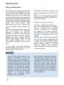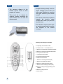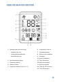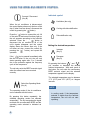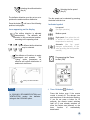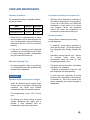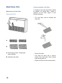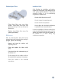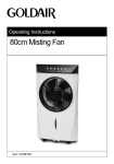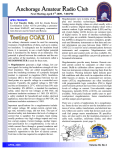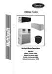
1
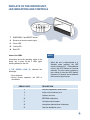
42XQ
42XQA
42XQ : Cooling only direct expansion Fan Coil Unit (Wireless Control)
42XQA : Cooling only direct expansion Fan Coil Unit (Wired Control)
Thank you for choosing Carrier!
You can be sure that you’ve made a wise choice, because the
same pride we take in manufacturing the Carrier equipment
installed in the Astrodome in Texas, in the Sistine Chapel, in
the Capitol – the seat of the US Congress – and in thousands
of other installations worldwide, is embodied in the design of
the unit you have just purchased.
One of the greatest benefits to await you when using your air
conditioner is that, in addition to maintaining a pleasant
temperature in the area where it is installed, the ambient air is
also filtered and dehumidified, thus improving the quality of the
air you breathe.
This manual has been created to familiarize you with all of the
technological features and benefits which this air conditioner
unit can offer.
This manual also contains important information regarding the
maintenance of your new air conditioner, servicing the unit
and, above all, running it in an economical way. Set aside a
few minutes to carefully read through the contents of this
manual and learn to optimize the use of your new Carrier
device in terms of personal comfort and economy of operation.
CONTENTS
PRECAUTIONS
3
Safety considerations
3
DISPLAYS OF THE INDOOR UNIT, LED INDICATORS & CONTROLS
6
Error codes
6
Emergency operation
7
REMOTE CONTROL
8
Using the selected functions
10
Using the wireless remote control
11
Using the wired remote control
17
Setting the operating mode
19
INFORMATION ABOUT FILTERS
21
CARE AND MAINTENANCE
22
Operating conditions
22
Operation during power outages
22
PRACTICAL TIPS
23
Cleaning the Indoor Unit
24
Cleaning the Outdoor Unit
24
Cleaning the filters
25
PRECAUTIONS
Safety considerations
The installation, servicing and maintenance
of air conditioning equipment may be
hazardous due to the pressure which the
refrigerant gas exerts on the interior, and
its electrical components. Only specialized
and professionally qualified personnel may
install, repair or perform servicing work on
air conditioning equipment. Non-specialized
people
may
only
perform
basic
maintenance work such as: cleaning the
coils and cleaning and/or replacing the
filters.
All other types of maintenance work may
only be performed by specialized
personnel. To perform such work, the
installer must follow the safety standards
applicable, and must wear safety goggles,
clothing and gloves suitable for this
purpose. Appropriate protection must be
used during welding work; a fire
extinguisher must always be kept close to
hand.
For your safety, read these instructions
through carefully and respect all of the
labels marked WARNING below.
WARNING
Recognize the safety information
The symbol “ ”! indicates a safety alert.
When you see this symbol, it is because
there is a potential risk of material
damage or personal injury. Understand
the meaning of the words DANGER,
WARNING AND CAUTION. These words
are used in conjunction with the alert
symbol.
DANGER means situations with a severe
risk to injury to people, including the risk
of death. The word WARNING means
situations which could result in personal
injury, including death. The word
CAUTION indicates unsafe practices
which could result in minor personal injury
or material damage.
!
• Do not attempt to interconnect units from
different manufacturers without first
consulting your Carrier representative or
an engineer specializing in air conditioning.
The incompatibility between the indoor and
outdoor unit and its control devices could
cause serious problems for both units and
invalidate the manufacturers’ warranty
coverage. Carrier accepts no liability and
will cancel the product warranty if these
installation instructions are not followed as
indicated, or if the wiring is changed.
Consult
your
preferred
Carrier
representative for further details.
3
WARNING or CAUTION contained in this
manual or attached to the housing of the
unit.
Consult your local regulations applicable
with respect to electrical installations for
special requirements.
• Before installing, modifying or performing
servicing work on the system, check that
the electrical power supply to the unit has
been switched off. Check that there is not
more than one power switch. Check and
label each switch present with the
appropriate wording. Electric shocks can
cause personal injury, and even death. If
the power supply cable is damaged, it
must be replaced only with an authorized
Carrier spare part by its network of
authorized dealers.
CAUTION
!
DISCONNECTING THE UNIT FROM
THE MAIN POWER SUPPLY
These units must be connected to the
main electrical power supply through
a circuit-breaker or switch fuse with
an appropriate capacity and with a
minimum separation between the
contacts of 3mm. If this is not
possible,
a
contact/container
combination equipped with an active
earth wire must be used. The contact
must have easy access after
installation. The contact must be
disconnected from the receptacle to
ensure that no electrical power gets to
the unit. It is vitally important to follow
the safety standards in force at the
connection location and also to check
that the electrical power supply is
actively equipped with an earth cable
WARNING
Do not spray flammable aerosols near to
the unit. The unit may be damaged if it
comes into contact with gasoline, solvents,
benzene, insecticides or other chemical
substances.
To prevent electric shocks, never splash
water into either the indoor or outdoor
units.
!
Do not attempt to disconnect the unit
at the main power switch. Always use
the unit’s control when you want to
disconnect the system.
Do not insert your hands or fingers, or
place objects inside the air discharge grille
of the outdoor unit, because the fan
rotates at very high speeds, which may
cause serious personal injury.
4
Use only a circuit-breaker with a suitable
capacity.
Keep the unit away from heat sources. High
temperatures may cause physical damage to
the unit.
Do not obstruct the air discharge of any of the
indoor and outdoor unit. Doing so, blocks the
airflow, reducing the cooling capacity and
causing the unit to malfunction.
In summer, prevent sunlight from entering the
air-conditioned area as far as possible. You
can do this by using curtains or blinds on the
windows.
The manufacturer accepts no liability in the
event of damage caused by: mistakes or
changes when establishing the electrical
connections or refrigerant gas connections,
during installation or due to the inappropriate
use of the equipment. Failure to observe
these instructions will immediately invalidate
the warranty of your unit.
Use the voltage indicated on the unit’s data
plate. Using a voltage different from the
specified voltage may cause very serious
damage to the unit.
This unit will only operate correctly if it is
installed
and
tested
by
personnel
professionally qualified and trained for such
work.
5
DISPLAYS OF THE INDOOR UNIT,
LED INDICATORS AND CONTROLS
T : EMERGENCY and RESET button
S : Receiver of remote control signal
P : Green LED
R : Yellow LED
Q : Red LED
NOTE
Indoor Unit LEDs
Information about the operating mode of the
indoor unit is given by the 3 LEDs (lightemitting diodes) on the unit.
0 THE GREEN LEAD (P) indicates the
followings:
• Error diagnosis
• During normal operation, the LED is
illuminated.
ERROR CODE
• When the unit is disconnected or in
Standby mode (waiting), the LED
remains switched off. If a breakdown
occurs, the LED flashes at 5-second
intervals. The error code is shown by
the number of times the LED flashes.
A pause of 5 seconds occurs between
the luminous signal cycles.
DESCRIPTION
3
Ambient temperature sensor error
4
Indoor unit coil sensor error
7
Outdoor unit error
10
EEPROM malfunction
11
Corrupted serial number
12
Incomplete address/zone information
13
Gas flow distribution error
6
0 THE RED LED (Q) indicates the following
information
• During normal operation, the LED is
switched off.
• During defrosting, the LED is illuminated.
• During the testing of the electrical
connections, the LED flashes at 1
second intervals.
0 THE YELLOW LED (R) indicates that the
unit is operating in timer mode. During this
operating mode, the LED is illuminated. If
timer mode is active and the unit is reset
immediately after a stop, this LED flashes
after receiving a new signal from the unit.
NOTE
• Positioning of the selector key: the
units leave the factory configured for
the underceiling position.
CONSOLE
: Position 1
UNDERCEILING : Position 0
If in doubt, refer the Installation and
Operation Manual.
“EMERGENCY button” (T)
This may be used when the remote control is
not working or has been lost.
Emergency Operation
When the unit is in OFF mode
(disconnected) and you
press the
emergency button for 5 seconds, the unit
starts operating as follows:
•
•
•
•
Automatic mode
Temperature at 22°C
Automatic fan speed
The air deflectors are positioned
automatically according to the operating
mode – see note
• Timer deactivated during cleaning or
replacement of filter
7
NOTE
According to the signal received via the
remote control, the unit starts operating
according to the command selected.
“RESET” (T)
This button must be pressed for one
second to revert to normal operation of the
unit after cleaning work or replacing the
filter.
REMOTE CONTROL
The remote control works with 1.5 V
batteries. When the battery icon appears on
the display of the remote control, it’s time to
replace the old batteries.
CAUTION
!
Before replacing the batteries, the
device must be disconnected.
Inserting the batteries
• Open the battery compartment on the
back of the remote control. To remove the
small cover, press down the small tab in
the direction indicated by the arrow in the
diagram.
• Remove the old batteries and insert new
ones. The remote control requires two
batteries (1.5V type AAA).
• Press the “o” button with a sharp-pointed
object to reset the remote control.
NOTE
• The average life of the batteries
under normal conditions of use is
approximately one year.
• If the air conditioner does not
function as normal after the
remote control batteries have
been replaced, remove the
batteries again, reinsert them and
press the “o” button again after 5
seconds
8
NOTE
• The maximum distance for the
infrared remote control to work
properly is 5 metres.
• There must be no objects, for
example, curtains, obstructing the
space between the unit and the
remote control.
NOTE
• Sunlight shinning directly onto the
signal reception area of the unit
may cause difficulties in receiving
the signal emitted by the remote
control.
• The remote control must be pointed
towards
the
device’s
signal
reception area when you press the
desired button.
• The electronic control system emits
an acoustic signal (beep) to confirm
the reception of the emitted
message.
Reading on the display or viewfinder
A. Operating mode selection button
B. ON/OFF button – Connect/disconnect
C. Button for increasing the selected temperature
D. Button for reducing the selected temperature
E. Fan speed selection button
F. Customized control button
G. Customized selections button
H. Deflector control button
I. Button for connecting the timer (ON)
J. Button for the daily timer (DAILY)
K. Button for canceling the timer setting
L. Button for disconnecting the time (OFF)
M. Button for setting the night operating mode
(SLEEP)
N. Button for setting the time
O. Reset button
9
USING THE SELECTED FUNCTIONS
6.
Configuration of the unit
• Ventilation (fan only)
7.
Low battery indicator
• Cooling with dehumidification
8.
Position of the air deflector
• Dehumidification only
9.
Fan speed
1. Operating mode (from left to right):
10. Active customization
2. Signal transmission symbol
11. Timer ON selected
3. Temperature reading
12. Night timer activated
4. “Address” selector
13. Day timer activated
5. Temperature measuring unit (°C or °F)
14. Timer ON, OFF and clock
15. Timer OFF selected
10
USING THE WIRELESS REMOTE CONTROL
Connect / Disconnect
(Key B)
Indicated symbol
Ventilation (fan only)
When the air conditioner is disconnected,
the control display shows only the hour of the
day (if other icons are shown, disconnect the
control by pressing the “
”button).
Press the “
”button to connect the unit. All
of the selected and saved functions light up;
the unit operates according to the functions
selected. Press the “
”button to
disconnect the air conditioner. All of the
unit’s signals disappear and the control
display shows the current time only. If the
unit does not stop, connect the control (by
pressing the “
”button) and repeat the
operation.
If the “ ”button is pressed immediately after
the disconnection of the unit, the unit only
starts operating again after 3 to 5 minutes
due to the protection against the frequency
cycle of the compressor.
The unit only emits the BEEP acoustic signal
when the orders have been received
correctly.
Select the Operating Mode
(Key A)
Cooling with dehumidification
Dehumidification only
Setting the desired temperature
Increase
(Key C)
Decrease
(Key D)
By pressing the buttons “
” and “
”,
you increase or decrease the desired
ambient temperature. With each touch of
the button, the unit emits the confirmatory
BEEP acoustic signal and the selected
temperature appears on the display.
The selected temperature may be between
17°C (63°F) and 32°C (90°F) at 1-degree
intervals.
NOTE
The operating mode of the air conditioner
can be selected with this button.
By pressing this button repeatedly, the
available operating modes are selected
sequentially. The unit recognizes the signal
received with a confirmation BEEP and the
operating mode selected is indicated as
follows:
11
In cooling mode, if the temperature
selected is higher than the ambient
temperature, the unit will not start
operating.
Selecting the airflow direction
(Key H)
Selecting the fan speed
(Key E)
The deflector direction must be set so as to
optimize the ambient airflow distribution.
The fan speed can be selected by pressing
the button with the icon
Press the button
until one of the following
positions is displayed:
Indicated symbol
Icons appearing on the display
The airflow direction is adjusted
automatically.
The deflector will
remain in the pre-selected position,
according to the operating mode.
6 different airflow directions
may be selected.
The deflector will continue to swing
downwards and upwards.
The
“Swing” option guarantees an
effective and uniform distribution of
ambient air at all times.
Low speed
(for night operation)
Medium speed
High speed (from when the unit
is turned on until the desired
temperature is reached)
Automatic (the fan speed
changes automatically to the
value providing the best possible
comfort)
Programming the Timer
to start (ON)
Cooling with dehumidification
NOTE
In COOLING, DE-HUMIDIFICATION and
VENTILATION modes, the deflector
swings to the COOLING option.
1. Timer ON button
(Button I)
Press this button even if the remote
control is turned off. The relevant icon
and the picture of the clock start flashing.
If you do not press a button for 10
seconds, the remote control switches
itself off (it was already switched off
when the button was pressed), or the
timer
function
is
automatically
deactivated.
12
2. HOUR and MINUTES buttons
( ∧ and ∨ buttons)
If the unit is connected, the only possible
selection is the time of starting operation.
The unit operates with the selections
shown on the display.
3. HOUR and MINUTES buttons
( ∧ and ∨ buttons)
If the unit is disconnected: select the
operating start hour and use the
temperature control buttons ( ∧ and ∨
buttons).
First select the hour and then confirm by
pressing the button
. Then select the
minutes using the buttons ∧ and ∨ . To
set the clock permanently, press button
again.
4. Operating mode
Select the operating mode of the unit.
The icons begin to flash. To select the
mode, use the M button.
After selecting the mode, press the
button. The icon of the selected mode
starts flashing.
5. Desired temperature
To select the desired temperature (the
value will be flashing), use the ∧ or ∨
buttons.
Press button
to confirm the selection.
The numbers stop flashing.
6. Fan speed
Select the fan speed using the
button.
After making your selection, press button
to confirm. The icon stops flashing.
13
7. Positioning the air deflector
This icon now flashes. Use button
select the desired position.
to
Press button
to confirm. Now all of the
icons are fixed on the display. If you want
to cancel the selections made up to now,
press button X; if you want to cancel the
selections since the timer was set, press
button
and then button X
Programming the Time to stop (OFF)
1. TIMER OFF button
(Button L)
Press button
.
The timer OFF icon and the hour selection
numbers start flashing.
This function may be selected even with
the remote control disconnected.
2. HOUR and MINUTES selection buttons
( ∧ and ∨ buttons)
To select the clock, press the ∧ and ∨ .
To toggle between hours and minutes,
press button
.
Press button
again to confirm.
Customization
(Button G and F)
and
If you want to save a customized operating
mode which you can reactive at any time,
complete the following steps:
1. With the remote control connected or
disconnected, press button
and keep it
pressed down for more than 5 seconds.
The customization icon
starts flashing
on the display.
Daily timer
(DAILY - button J)
Press button
when timer ON or OFF is
active. The icon appears on the display. In
this way, the saving of the timer ON and OFF
is repeated daily. To deactivate the daily
function, press button
again.
Combining the TIMER ON, OFF and
DAILY programming
2. Press button M to select the operating
mode.
If you want the unit to start operating at
5:30pm and stop operating at 10:30pm,
proceed as follows:
3. Press button ∧ and ∨ to select the desired
temperature.
1. Select timer ON for 5:30pm
4. Use button
5. Use button
position.
to select the fan speed.
to select the deflectors’
2. Select timer OFF for 10:30pm
3. Select the desired operating mode
(button M )
6. After entering all the selected options,
press button
to save them.
NOTE
After this procedure, all of the
selected and saved functions will be
able to be activated using button
,
regardless of the operating mode of
the unit.
If you want to stop the unit at 10:30pm and
restart at 7:30am with the same operating
mode, proceed as follows:
1. Select timer OFF for 10:30pm during
operation
2. Select timer ON for 7:30am.
After entering customized mode, press one of
, ∧ , ∨ or
to exit. If you
the buttons: M,
want to change one or more saved settings,
return to point 1 and restart the setting
procedure.
14
If you want the daily operating mode to start at
530pm and stop at 10:30pm, proceed as
follows:
Programming the night timer
(SLEEP - button M)
1. Select timer ON for 5:30pm
2. Select timer OFF for 10:30pm
3. Press the button of the daily operating mode
(Button
)
Press this button to set the night timer (SLEEP)
with the remote control connected. The icon
appears on the display. This procedure allows
you to set the remaining operating time of the
unit.
1. “1:hr” appears on the display, together with
the icon.
2. Press button ∧. The
display
shows
the
following selections in
the sequence:
Canceling the ON, OFF and DAILY
TIMER programming
1 hr, 2 hr, 3 hr, 4 hr, 5 hr,
6 hr, 7 hr, 8 hr and 9 hr
3. Once you have selected - using the buttons
∧ or ∨ - the remaining operating hours,
press button
again to confirm.
1. If you want to cancel the selection of ON or
OFF timer, press the buttons, following this
sequence:
4. After the night timer has been set, the unit
will check the selected temperature to
prevent excessive cooling during operation.
• Button
or
• Button X
To deactivate the daily
function, press button
operating
mode
NOTE
The daily operation function will remain
active until one of the two timers (ON or
OFF) is activated.
15
Buttons for setting the time
resetting
(Button N and O)
and
Press the clock setting button
to adjust the
real time. Press the button “o” with a sharppointed object, if the remote control is not
working properly or after replacing the
batteries.
CAUTION !!!
Setting the hour
(Button N)
1. With the remote control
connected or disconnected,
press button
.
The air conditioner will not work if there are
curtains, doors or other objects blocking the
signal sent from the remote control to the
unit.
2. The numbers of the hour
start flashing. Press button
∧ or ∨ to set the desired
hour.
Press button
to switch to
the minutes, in order to set
them.
3. To make this selection,
always use buttons ∧ or ∨.
If the infrared signal receiver of the indoor
unit is directly exposed to the sun’s rays,
the equipment will not function properly.
Block the incidence of sunlight until the
exposure has been eliminated.
4. After setting the hour, press
button
to confirm.
NOTE
Together with the remote control, you will
receive a mounting support to put it inside.
Attached the support the wall.
“Address” Selector
• If there are two indoor units in the
same room, you can connect one
remote control to one indoor unit
and the other remote control to the
other unit, or you can control both
units using just one remote control.
• For the configuration, consult the
Installation & Start-up Instruction’s
Manual.
NOTE
Always use the remote control to set
the position of the air deflectors;
otherwise operational anomalies
may result. Disconnect the unit and
reconnect it when manually setting
the grid outside of the range.
16
Control to the left and right
Specifications
If you want to set the direction of the air to
the right or left, adjust the deflector by hand
after opening the horizontal deflector.
• Operating Modes:
Off (disconnected), Cool (refrigeration),
Dry (dehumidification), and
Fan only (ventilation)
• Fan Speeds: Low, Medium, High and Auto
• Deflector temperature: Between 17 and
32°C (63 and 90°F)
NOTE
DO NOT adjust the deflector by hand
if the unit is operating in SWING
mode, since this may damage the air
oscillation mechanism.
• Cancellation of temperature sensor of
unit: Allows you to use the air sensor
located on the remote control instead of
the sensor located inside the unit.
• Diagnostics: Detects errors in the remote
control air sensor.
0 The code “A1” shown on the display
indicates this anomaly.
(up)
WIRED REMOTE CONTROL
General Information and Specifications
(down)
“UP” and “DOWN”
buttons
Buttons for increasing or
decreasing the temperature
or selecting the air deflector
modes
“AUTO”
or
“SWINIGING”
Operating mode selection
button.
Air deflector or fan selection
button.
A = Reading on the display
B = Increase temperature / change the air deflector
setting button
C = Decrease temperature / change the air deflector
setting button
D = Fan speed selection button
E = Operating mode selection button
17
Display the selected functions
Control Powered Up
All of the segments of the Remote Control
Display must be powered up for five
seconds. Information about the operating
mode, fan speed, desired temperature and
configuration must be read from the
Microprocessor inside the Remote Control. If
the EEPROM values are not valid, the
following must be used by default.
1. Disconnected
2. Selected temperature/ambient temperature
3. Set temperature
Example of normal operation
4. Deflector operating position
5. Fan speed
6. Refrigeration
7. Dehumidification only
When connected, the control display
appears.
Operating Mode
= AUTO
Fan Speed
= AUTO
Desired Temperature
= 22°C
°F or °C
= C
Deflector (louver)
= AUTO
Cancellation of the Ambient Thermistor
= OFF
Refrigeration Only
= Cool
18
SETTING THE OPERATING MODE
COOL and DRY modes
• ICON of the Operating Mode.
“MODE” button
Pressing the “MODE” button causes the
operating mode to change. The “MODE”
button must be released and then pressed
again to switch to the next mode. The active
mode will always be displayed in normal
operation.
• Ambient Temperature: if configured by
canceling the temperature sensor of the
ambient environment unit (operated by
the environment controller); otherwise the
temperature is selected by the user with
the “SET TEMP” icon.
• FAN/LOUVRE icon with the Fan and
Louver settings – air deflector – selected
by the user.
NOTE
If the “MODE” button is not
pressed for 15 seconds, the next
command always changes the
mode to OFF.
The available operating modes to select from
are:
Available Buttons
• All the Buttons are available.
DRY
Dehumidification Operation
Remote Refrigeration Only
OFF (disconnected)
COOL
Refrigeration Operation
COOL (refrigeration)
DRY (dehumidification)
FAN ONLY (ventilation)
OFF Mode
• OFF mode
• Ambient Temperature: if configured by
canceling the ambient environment
sensor. Otherwise none.
Available Buttons
• “MODE” button
19
FAN ONLY mode
“FAN” button
FAN ONLY
Operation with fan ventilation only
Setting the fan speed.
When the “FAN” button is pressed, the fan
speed is changed.
To reach the desired speed, the “FAN”
speed button must be pressed and then
released.
Low, Medium,
High or Auto.
Up
“UP” and “DOWN”
buttons
down
0 The icon on the display show that a
change has occurred.
Selecting the desired temperature
NOTE
NOTE
• Press the buttons “UP” - hotter, or
“DOWN” - colder, to change the
temperature.
The setting of the AUTO mode is
shown by the flashing of the medium
and High speed icons of the fan.
• The maximum temperature of the
device is 32°C (90°F) and the
minimum temperature is 17°C
(63°F).
Low
Whenever the set point is being displayed,
the “SET TEMP” icon is illuminated.
Whenever the display mode changes from
°F to °C, the setpoint is set to the default
start-up values of 22°C for “°C” mode and
72°F for “°F” mode.
If the air sensor embedded in the remote
control is activated, the display shows the
ambient temperature after a few seconds.
Medium
High
Auto (automatic)
The fan speed changes
automatically from the
requested value to an
ideal temperature. When
this function is activated,
the dotted symbols flash.
20
Air Deflector Control
Information about Filters
• Keep the “FAN” button pressed down for
5 seconds.
• The selected air deflector setting is
displayed.
• By pressing the “UP” and “DOWN”
buttons, you can change the desired
configuration of the air deflector.
• Air Filters (optional)
- Option 1: Electrostatic
Activated Carbon Filter.
- Option 2: Electrostatic
Photocatalyzer Filter.
Filter
+
Filter
+
• The air filters trap dust and small
particles.
The two settings will be displayed as follows:
AUTO
Automatic
positioning
of
air
deflector to the best position for the
selected operating mode.
SWING (oscillation)
The deflector swings continuously.
• Press the “FAN” button to exit air deflector
control
selection
mode.
• This mode will exit automatically after no
button has been pressed for 10 seconds.
• The only way to change the operating
mode is by returning to this menu.
21
• The optional combination Electrostatic
Filter + Photocatalyzer Filter traps
microscopic dust particles and cigarette
smoke in the air-conditioned area.
Electrostatic Filter
+
Activated Carbon Filter
Electrostatic Filter
+
Photocatalyzer
Filter
Filter Life Cycle
• The useful life of the filters described
above varies according to the quantity of
cigarette smoke, the size of the airconditioned area and the operating time.
• The air filters may be cleaned with a
vacuum cleaner or rinsed with a water jet
after one month of use.
• The useful lifetime of the optional
activated carbon filters is approximately 2
years and the useful lifetime of the
electrostatic filters is around 3 months.
The activated carbon filters may be
washed with a neutral detergent, rinsed
with water and left to dry in the sun.
• The useful lifetime of the Photocatalyzer
filters is approximately 2 years. This type
of filter may be washed under running
water and reactivated with direct exposure
to the sun’s rays. The exposure time is 6
hours after 3 months’ of use.
CARE AND MAINTENANCE
Operating Conditions
Prevention of freezing in the indoor unit
The temperature ranges compatible with the
unit are as follows:
• When the unit is operating in conditions of
low ambient temperature, ice may appear
on the coil of the indoor unit. When the
temperature of the indoor coil is below
zero degrees Celsius, the electronic
control will cause the compressor to
disconnect to protect the freezing unit.
MODE
INDOORS
OUTDOORS
REFRIGERATION
21~32°C
21~46°C
DEHUMIDIFICATION
17~32°C
12~46°C
Normal operation
• When the unit is operating below or above
these conditions for an extended period of
time, the diagnostics system will detect a
malfunction and the unit will not function
properly.
• If the unit is operating under abnormal
conditions for an extended period of time,
or under extreme humidity, condensation
may be formed inside the unit.
Minimum Operating Time
• In normal operations, there is a minimum
of 3 minutes between each shutdown and
startup of the compressor.
WARNING !!
Operation in the event of power outages
• When an electrical power outage occurs
and the unit is in operation, the operating
conditions are saved and restored
automatically when the electricity returns.
Some of these events may occur during
normal operation:
• A “warbling” sound during operation or
when the unit stops – This is the sound of
the refrigerant gas flowing through the
unit.
• Bad odors coming from the unit – Smoke
or
cosmetic
odors
which
have
accumulated while the room air was
circulating through the unit.
• The green light on the indoor unit flashes
and there is no ventilation.
- Indicates a malfunction of the unit, and
the compressor will stop operating.
• A loud noise can sometimes be heard
while the unit is operating or when the unit
is switched on - this is the sound of the
plastic expanding due to rapid changes in
temperature.
• The programming of the TIMER will be
lost.
• On leaving your house during a power
outage, disconnect the indoor unit to
prevent it from switching itself on
automatically when the power returns.
22
PRACTICAL TIPS
Optimal comfort with low consumption
If you know that your air conditioner
will not be used for an extended
period of time:
• Ensure that you maintain the temperature
of your house within the comfort zone.
• When the unit is operating in cooling
mode, prevent sunlight from entering the
house. Whenever possible, close the
curtains or lower the blinds.
• Wash and dry the filters and replace them
in the unit.
• Make the unit operate in ventilation only
for at least half a day to dry the inside
completely
• Do not cover the front of the unit or
obstruct the air intake or discharge. An
obstruction may cause a reduction in the
air quantity and reduce the efficiency of
the equipment, which may lead to a
malfunction.
• Disconnect the main power supply switch.
• Remove the remote control batteries.
• Clean the indoor unit and the outdoor unit
23
Cleaning the Indoor Unit
Cleaning the Outdoor Unit
• Always disconnect the main power supply
before unit performing any cleaning work.
• From time to time, clean the area around
the outdoor unit and remove the waste
that may have accumulated and could
cause a reduction in air circulation.
• Only use a clean damp cloth and soap.
• Do not spill any liquids on the unit.
• Do not use flammable products, solvents
or detergents containing abrasives: these
may damage the surface coating of the
unit.
• Avoid any contact with heat sources,
since hot air may damage the surface
coating of the unit.
• The remote control may only be cleaned
with a clean cloth.
24
PRACTICAL TIPS
Maintenance and User Guide
Cleaning the Filters
Cleaning washable cloth filters
To determine how often these filters should
be washed, you should take 1 month of
operation as the basic length of time
between washings.
• The cloth filters must be washed with
water only.
A-
B-
A - Photocatalyzer filters + Electrostatic
filters (optional)
B - Washable cloth filters
• Remove the filters.
• First clean the filters with a vacuum
cleaner; then wash them under running
water and dry them off.
• Replace the filters in their correct position.
25
Photocatalyzer Filters
Installer’s Guide
After finishing the installation and testing,
explain the main points of this Manual to the
user, giving special attention to the main
operating modes of the air-conditioning
equipment as stated below:
• How to switch the unit on and off.
• How to change the operating mode.
• How to select the temperature.
• Clean these filters once every three
months. Wash them with water and
leave them to dry in the sun for two or
three hours.
• How to adjust the air direction deflectors
to optimize the air current direction.
• Replace these filters after every five
years approximately.
Leave the Installation & Start-up Instruction’s
manual and the Maintenance manual of the
indoor and outdoor units with the owner, to
be referred to in future during any
maintenance operation.
Maintenance
After the unit has been shut down for an
extended period of time and before starting it
up again, perform the following:
• Inspect and clean the outdoor unit,
especially the coil.
• Clean and replace the indoor unit’s
filters.
• Check and clean the condensate tray of
the indoor unit.
• Do the same with the outdoor units on
the models which possess a heat pump.
• Check the sockets of the electrical
connections.
26
Parent Pt No.: 42XQ-402-001
OM Pt No.: 42XQ-502-002
Printed in Malaysia
NEW
42XQ
08
2005
Manufacturer reserves the right to discontinue, or
change at any time, specifications or designs
without notice and without incurring obligations.