1
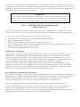
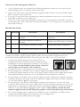
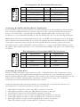
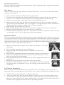
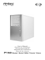
User’s Manual
Manuel de l’utilisateur
Anwenderhandbuch
Manuale per l’operatore
Manual del usuario
P150 Super Quiet Mini Tower Case
At Antec, we continually refine and improve our products to ensure the highest quality. So it's
possible that your new case may differ slightly from the descriptions in this manual. This isn't
a problem; it's simply an improvement. As of the date of publication, all features, descriptions,
and illustrations in this manual are correct.
Disclaimer
This manual is intended only as a guide for Antec's Computer Enclosures. For
more comprehensive instructions on installing your motherboard and peripherals,
please refer to the user's manuals which come with your components and drives.
P150 — SUPER QUIET MINI TOWER CASE
USER'S MANUAL
The P150 is designed with Quiet Computing™ in mind. Apart from the solid steel structure
(1.0 mm thick steel), there are several unique design features that make this case quiet and cool.
1.
2.
3.
4.
5.
6.
7.
Two-layer (steel/plastic) side and top panels to deaden noise.
Dual hard drive mounting system for maximum noise reduction.
Quiet 120mm TriCool rear fan.
Dual front 92mm fan mounts for spot cooling hard drives
Intake vents along the sides of the front bezel to prevent noise from leaking toward to the user.
Built-in cable organizer to tuck away cables.
Neo HE 430 high efficiency power supply.
NEO HE Power Supply
The Neo HE 430 power supply installed in this case supports the newest ATX12V version 2.2
specifications. Enhanced output power distribution supports the newest Intel and AMD
processor requirements. Three +12V outputs deliver safer and more reliable power to your
system's components. With up to 85% efficiency, this power supply saves energy and money on
your electrical bill compared to typical power supplies. Neo HE power supplies
generate less heat because of the high efficiency which keeps the power supply cooler and
prolongs its working life. Also included are a variety of industrial-grade protective circuitries:
OCP (over current protection), OPP (over power protection), OVP (over voltage protection),
SCP (short circuit protection), and UVP (under voltage protection).
Special Quiet Computing Fan Operation
Neo HE power supplies feature an innovative design that decreases noise during normal use, but
which allows for superior cooling capabilities as loads increase. Owing to its ultra high efficiency
and low heat generation, Neo HE can utilize an 80mm exhaust fan that rotates slowly and
quietly to blow hot air out of the power supply, speeding up as heat increases.
This power supply includes Universal Input and Active Power Factor Correction (PFC).
Universal Input allows you to connect your Neo HE power supply to any AC power outlet
between 100~240V without having to worry about setting a voltage switch. Active PFC
improves the power factor value of the power supply by altering the input current wave shape,
helping the power plant provide power to users more efficiently.
2
Connectors: Neo HE power supplies are ATX12V version 2.2 form factor compatible. The Neo
HE430 includes a 24-pin main power connector with detachable 4-pin connector, and a 4-pin
+12V power connector. In addition, Neo HE includes six 4-pin peripheral connectors, four
15-pin Serial ATA Connectors, and PCI Express Power Connector.
Power Switch: This power supply comes with a main power switch. Make sure you turn the switch
to the ON ( I ) position before you boot up your computer for the first time. In normal
operation there is no need to turn the switch to the OFF (O) position since the power supply is
equipped with a soft on/off feature which turns your computer on and off through the soft
switch on your computer case. You may need to turn the switch to the OFF position
occasionally should your computer crash and you cannot shut it down with the soft switch.
Advanced Cable Management System - Neo HE power supplies feature Antec's Advanced Cable
Management System. It allows you to use only the power cables that you need, thereby reducing
clutter and improving airflow inside your case. Inside the package, apart from a power cord, you
will find the following cables (see Picture 1):
Picture 1
Attached to the power supply, you'll find the following:
1. Five 6-pin output sockets, for use with the wire sets to power your drives and other
peripherals.
2. 4-pin +12V connector
3. A 24-pin configurable main power connector with detachable 4-pin section for 20-pin
applications.
3
Advanced Cable Management Wire Set.
4.
One Y-adapter with one standard 4-pin Molex peripheral connector at one end and two
female Floppy power connectors at the other end.
5. One set of wires with a 6-pin PCI Express graphic card connector at one end and a 6-pin
PSU connector at the other end.
6. Two sets of wires with three standard 4-pin Molex peripheral connectors at one end and a
6-pin PSU connector at the other end.
7. Two sets of wires with two SATA drive connectors at one end and a 6-pin PSU connector
at the other end. Note: The SATA connectors include a +3.3V output so you can power the
latest SATA devices.
Modularized Cables:
#
Quantity
Part Name
Description
4
1
14 cm Molex to Floppy connectors
w/cable
includes one Molex and two floppy
connectors
5
1
60 cm PCI Express connector
w/cable
Includes one PCI Express connector
6
2
77 cm Molex connector w/cable
includes three Molex connectors
7
2
73 cm Serial ATA connector w/cable includes two Serial ATA connectors
This power supply is backwards-compatible to previous ATX specifications. To make sure you
connect your power supply properly, please refer to the user manual supplied with your
motherboard and peripherals before connecting the Neo HE to any of your devices.
1. Connect the 24-pin main power connector. If your
motherboard uses a 20-pin connector, detach the 4-pin
attachment on the 24-pin power connector (see pictures 2
and 3). Note: the detachable 4-pin section cannot be
used in place of the 4-pin +12V connector.
Picture 2
Picture 3
2. Connect the 4-pin +12V connector to the motherboard.
3. In the package, you will find 2 sets of power supply-to-peripheral Molex connectors.
Connect the 6-pin connector to any of the 6 pin sockets on the power supply and connect
the peripheral Molex connectors to your peripheral devices. Repeat as necessary.
4. In the package, you'll find 2 sets of power supply-to-SATA connectors. Connect the 6-pin
connector to any of the 6-pin sockets on the power supply and connect a SATA connector
to your SATA drives. Repeat as necessary.
5. In the package, you'll find one PCI Express graphic card connector. It's the only 6-pin
connector with 3 yellow wires and 3 black ones. Connect the 6-pin connector to any of the
6-pin sockets on the power supply and connect the 6-pin PCI Express connector marked
"PCI-E" to your PCI Express graphic card if needed. Note: Please consult the user
manual supplied with your PCI Express graphic card for detailed usage instructions.
6. If you have a floppy drive, connect the Y-adapter to any of the Molex connectors and
connect the female floppy power connector to your floppy drive.
7. Connect the power cord to the power supply.
4
Setting Up
1. Place the case upright on a flat, stable surface.
2. Loosen the thumbscrews from the left side panel. Remove it by swinging it out. Note:
Don't use your fingernail to pry or lift the panels.
3. Inside the case you should see the power supply, some wiring with marked connectors (USB,
PWR etc.), an installed I/O panel, a power cord, a plastic bag containing modular PSU out
put cables, a toolbox with more hardware (screws, brass standoffs, plastic stands, etc.), and
six drive rails.
4. There are three plastic tabs on the left side of the bezel. They fasten the front bezel to the
metal chassis. Release the tabs from the top down to release the bezel.
5. Swing open the bezel to about a 45º angle and gently lift the bezel upward. The front bezel
will come off easily. Set the bezel in a safe place.
Installing the Motherboard
This manual does not cover CPU, RAM, or expansion card installation. Please consult your
motherboard manual for specific mounting instructions and troubleshooting.
1. Lay the case down, with the open side facing up. The drive cages and power supply should
be visible.
2. Make sure you have the correct I/O panel for your motherboard. If the panel provided with
the case isn't suitable, please contact your motherboard manufacturer for the correct I/O panel.
3. Line up your motherboard with the standoff holes, and remember which holes are lined up.
Not all motherboards will match with all the provided holes; this is normal, and won't affect
functionally. (In other words, there will likely be extra holes.)
4. Remove your motherboard by lifting it up.
5. Screw the brass standoffs into the threaded holes that line up with your motherboard. Do
not overtighten the standoffs. Some standoffs may be pre-installed for your convenience.
6. Place your motherboard on the brass standoffs.
7. Fasten your motherboard to the standoffs with the provided Philips-head screws. Your
motherboard is now installed.
Connecting the Front I/O
1. Connect the reset switch (labeled RESET SW) to your motherboard at the RST connector.
2. Connect the power LED (labeled POWER LED) to your motherboard.
3. Power switch (labeled POWER SW) connects to the PWR connector on the motherboard.
4. Connect the speaker (labeled SPEAKER) connector to the speaker connector on your
motherboard.
5. Hard drive LED (labeled H.D.D. LED) connects to the HDD connector on your
motherboard.
Connecting the USB Ports
You will find a single 10-pin connector on a cable attached to the front USB ports. This is an
Intel standard connector, which is keyed so that it can't be accidentally reversed as long as it is
connected to a proper Intel standard motherboard header. Connect the 10-pin connector to
your motherboard headers so that the blocked pin fits over the missing header pin.
Note: Please check your motherboard manual for your USB header pin layout and make sure it
matches the attached table. If it does not match this Intel standard, please call Antec customer
service at (800) 22ANTEC (North America) or +31 (0) 10 462-2060 (Europe) to buy a USB
adapter. This adapter will allow you to connect the front USB to your motherboard on a
pin-by-pin basis.
5
1
9
2
Pin Assignment for Front Panel USB connector
Pin
Signal Names
Pin
Signal Names
1
USB Power 1
2
USB Power 2
3
Negative Signal 1
4
Negative Signal 2
5
Positive Signal 1
6
Positive Signal 2
7
Ground 1
8
Ground 2
9
Key (No Pin)
10
Empty Pin
10
Connecting the IEEE 1394 (FireWire®, i.Link®) Port
You will find a single 10-pin connector on a cable attached to the front IEEE 1394 connection.
This is an Intel standard connector, which is keyed so that it can't be accidentally reversed as
long as it is connected to a proper Intel standard motherboard header. Connect the 10-pin
connector to your motherboard header so that the blocked pin fits over the missing header pin.
Note: Please check your motherboard manual for your IEEE 1394 header pin layout and make
sure it matches the attached table. If you intend to connect the front FireWire port to an IEEE
1394 add-on card that comes with an external-type IEEE1394 connector, please call Antec
customer service at (800) 22ANTEC (North America) or +31 (0) 10 462-2060 (Europe) to buy
an adapter. This adapter will allow you to connect the front IEEE 1394 port to the external-type
connector.
1
9
2
Pin Assignment for Front Panel IEEE 1394 Connector
Pin
Signal Names
Pin
Signal Names
1
TPA+
2
TPA–
3
Ground
4
Ground
5
TPB+
6
TPB–
7
+12V (Fused)
8
+12V (Fused)
9
Key (No Pin)
10
Ground
10
Connecting the Audio Ports
There is an Intel standard 10-pin connector (with 7 individual wires with connectors) coming
out from the front panel speaker and microphone connection. If your motherboard supports
Intel's standard onboard audio connector, you can plug in the 10-pin connector directly onto the
board. For a non-Intel standard audio connection, you will need to plug the 7 individual
connectors into the motherboard. See instructions below:
Locate the internal audio connectors from your motherboard or sound card. Consult your
motherboard or sound card manual for the pin-out positions.
1.
2.
3.
4.
5.
6.
Microphone signal pin: Connect the MIC connector to this pin.
Microphone power: Connect the MIC-BIAS connector to this pin.
Ground pin: Connect the AUD GND connector to this pin.
Front right speaker out pin: Connect the FPOUT-R connector to this pin.
Front right speaker out pin: Connect the FPOUT-L connector to this pin.
Rear right speaker out pin: Connect the RET-R connector to this pin.
Rear left speaker out pin: Connect RET-L connector to this pin.
6
Hard Disk Installation
This case offers two hard disk mounting options. We recommend against using both mounting
methods at the same time.
Tray Mount
There is a hard disk cage right under the external 5.25" drive. You can mount four hard drives
using the trays inside it.
1. Open the front bezel as described in Setting Up section.
2. Loosen the two thumbscrews. Swing open the fan cage and gently lift the cage upward to
remove it. You will see four drive trays with soft silicon grommets inside the cage.
3. Squeeze the metal clips on each side of the tray and slide the tray out.
4. Mount your hard drive into the drive tray through the bottom silicon grommets with the
special screws provided. Note: Don't over-tighten. Over-tightening the screws will harm the
vibration and noise reduction qualities of the silicon grommets.
5. Slide and lock the tray back into the case.
6. Find the appropriate power connector on the power supply and connect it to the device.
7. Repeat the same procedure for the other devices as necessary.
8. Put the front fan cage back to the case. If you plan to mount the optional 92 mm case fans,
you should do it now. See Cooling section for fan installation.
Suspension Mount
This is the ultimate hard disk mounting solution to reduce hard drive noise. There are three sets
of suspenders inside the cage to mount three hard drives. Each hard drive needs two suspenders
(front and rear) to mount. Note: please DO NOT transport your system with your hard disks
suspension mounted. The drives may slip from the suspenders causing damage to the hard
drives and to other components inside the case.
1. Remove the trays from the cages. Store them in a safe place. You won't
need them.
2. Twist the front suspender as shown in Picture 4.
3. Insert the hard drive through the front suspender from the front.
See Picture 5.
4. Twist the rear suspender and guide the hard drive through it. See Picture 6.
5. Adjust the hard drive position so it has al least 10mm clearance from the
front 92 mm fan (fan not included).
6. Find the appropriate power connector on the power supply and connect it to
the device.
7. Repeat the same procedure for the other drives as necessary.
8. Put the front fan cage back to the case. If you plan to mount the optional
92 mm case fans, you should do it now. See Cooling system section for fan
installation
Picture 4
Picture 5
Picture 6
5.25" Device Installation
There are four external 5.25" drive bays (one with 5.25" to 3.5" adapter). The top two drive
bays come with a universal drive door that allows you to hide your optical drive behind the door.
1. Carefully remove the metal plate covering the drive bay.
2. Take two plastic drive rails and mount them to the sides of the 5.25" device. Make sure to
use the rear set of the screw holes on the drive rails for the top two drive bays and use the
front set of screw holes for the lower two drive bays. Also make sure the clip on the end of
the drive rail is angled away from the device and facing forward.
7
3. Slide the device into the drive bay until you hear a click.
4. Mount the other devices accordingly.
5. Connect a large 4-pin connector from the power supply to the male 4-pin connector on each
of the devices.
To install a floppy or other external 3.5" device to the 5.25" to 3.5" adapter:
1. Slide the adapter out.
2. Place the drive to the adapter and fasten the drive with screws provided.
3. Find a 4-pin floppy power connector on the power supply and connect it to the male 4-pin
connector on the devices.
Cable Organizer
There are six hooks (cable organizers) located at the back of the hard drive cage. With them
you can tuck cables away to increase the airflow of the case. To get to the cable organizer you
need to open the right side panel.
Cooling System
The TriCool fan:
The case includes one 120mm TriCool fan installed in the rear. This fan has a three-speed switch
that lets you choose between quiet, performance, or maximum cooling. (See specifications
below.) The fan is installed so that the air is blowing out of the case. Connect a large 4-pin
connector from the power supply to the male 4-pin connector on the fan.
Note: The minimum voltage to start the fan is 5V. We recommend setting the fan speed to
High if you choose to connect the fan to a fan control device or to the Fan-Only connector
found on some of Antec's power supplies. A fan-controlled device regulates the fan speed by
varying the voltage supplied to it. The voltage may start as low as 4.5 V to 5V. Connecting a
TriCool set on Medium or Low to a fan-control device may result in the fan not being able to
start. The already lowered voltage from the fan control device will be further reduced by the
TriCool circuitry below 5V.
Specifications:
Size:
Rated Voltage:
Operating Voltage:
120 x 120 x 25.4 mm
DC 12V
10.2V ~ 13.8V
Speed
Input
Current
Air Flow
Static
Pressure
Acoustical
Noise
Input
Power
High
2000 RPM
0.24A
(Max.)
2.24 m³/min.
(79 CFM)
2.54 mm-H2O
(0.10 inch-H2O)
30 dBA
2.9 W
Medium
1600 RPM
0.2A
1.59 m³/min.
(56 CFM)
1.53 mm-H2O
(0.06 inch-H2O)
28 dBA
2.4 W
Low
1200 RPM
0.13A
1.1 m³/min.
(39 CFM)
0.92 mm-H2O
(0.04 inch-H2O)
25 dBA
1.6 W
The Front 92 mm Fan Mounts
You can install two 92 mm fans to the fan cage in front of the internal 3.5" drives. These fans
must be installed so that the air is blowing into the case. We recommend using Antec 92 mm
TriCool fans to balance quiet performance with maximum cooling. See our web site for product
information. Note: Please choose your fan speed wisely. In most cases, a medium or even low
speed setting will be enough to supply adequate cooling.
8
The Washable Air Filter
There is a washable air filter attached to the front of the 92 mm fan cage. From time to time it
will be necessary to wash the installed air filter. Not washing the air filter will result in higher
system temperatures and possible stability problems. We recommend checking the air filter at
least once a month initially. The frequency will change depending on system usage (users whose
systems run 24/7 will likely have to check/wash more often than those who don't use their
systems every day) and on environmental conditions.
9
Antec, Inc.
47900 Fremont Blvd.
Fremont, CA 94538
Tel: 510-770-1200
Fax: 510-770-1288
Antec Europe B.V.
Sydneystraat 33
3047 BP Rotterdam
The Netherlands
Tel: +31 (0) 10 462-2060
Fax: +31 (0) 10 437-1752
Technical Support
US & Canada
1-800-22ANTEC
[email protected]
Europe
+31 (0) 10 462-2060
[email protected]
www.antec.com
© Copyright 2005 Antec, Inc. All rights reserved. All trademarks are the property of their respective owners.
Reproduction in whole or in part without written permission is prohibited. Printed in China.
Version 1.0.2 8/05/2005