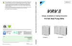
1
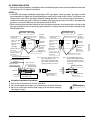
INSTALLATION MANUAL
III SYSTEM Air Conditioners
MODELS
〈BS unit〉
BSVQ36PVJU
BSVQ60PVJU
BSVQ96PVJU
English
Français
Español
Read these instructions carefully before installation.
Keep this manual in a handy place for future reference.
This manual should be left with the equipment owner.
Lire soigneusement ces instructions avant I’installation.
Concerver ce manuel à portée de main pour référence ultérieure.
Ce manuel doit être donné au propriétaire de l’équipement.
Lea cuidadosamente estas instrucciones antes de instalar.
Guarde este manual en un lugar a mano para leer en caso de tener alguna duda.
Este manual debe permanecer con el propietario del equipo.
BSVQ36PVJU
BSVQ60PVJU
BSVQ96PVJU
VRVIII SYSTEM Air Conditioners
Installation manual
CONTENTS
1
2
3
4
5
6
7
8
9
SAFETY CONSIDERATIONS ........................................................................................ 1
BEFORE INSTALLATION .............................................................................................. 4
SELECTING INSTALLATION SITE ............................................................................... 5
PREPARATIONS BEFORE INSTALLATION................................................................. 6
BS UNIT INSTALLATION............................................................................................... 7
REFRIGERANT PIPING WORK .................................................................................... 8
ELECTRIC WIRING WORK ......................................................................................... 13
INITIAL SETTING......................................................................................................... 16
TEST OPERATION ...................................................................................................... 17
1. SAFETY CONSIDERATIONS
Read these SAFETY CONSIDERATIONS for Installation carefully before installing air conditioning equipment. After completing the installation, make sure that the unit operates properly during the startup operation.
Instruct the customer on how to operate and maintain the unit. Inform customers that they should store this
Installation Manual with the Operation Manual for future reference.
Always use a licensed installer or contractor to install this product. Improper installation can result in water or
refrigerant leakage, electrical shock, fire, or explosion.
Meanings of DANGER, WARNING, CAUTION, and NOTE Symbols:
DANGER ..........Indicates an imminently hazardous situation which, if not avoided, will result in death
or serious injury.
WARNING ........ Indicates a potentially hazardous situation which, if not avoided, could result in death
or serious injury.
CAUTION .........Indicates a potentially hazardous situation which, if not avoided, may result in minor
or moderate injury. It may also be used to alert against unsafe practices.
NOTE ................Indicates situation that may result in equipment or property-damage accidents only.
DANGER
• Refrigerant gas is heavier than air and replaces oxygen. A massive leak could led to oxygen depletion, especially in basements, and an asphyxiation hazard could occur leading to serious injury or
death.
• Do not ground units to water pipes, gas pipes, telephone wires, or lightning rods as incomplete
grounding can cause a severe shock hazard resulting in severe injury or death. Additionally,
grounding to gas pipes could cause a gas leak and potential explosion causing severe injury or
death.
• If refrigerant gas leaks during installation, ventilate the area immediately. Refrigerant gas may produce toxic gas if it comes in contact with fire. Exposure to this gas could cause severe injury or
death.
1
English
• After completing the installation work, check that the refrigerant gas does not leak throughout the
system.
• Do not install unit in an area where flammable materials are present due to risk of explosions that
can cause serious injury or death.
• Safely dispose all packing and transportation materials in accordance with federal/state/local laws
or ordinances. Packing materials such as nails and other metal or wood parts, including plastic
packing materials used for transportation may cause injuries or death by suffocation.
•
•
•
•
•
•
•
•
•
•
•
•
•
•
•
•
•
WARNING
Only qualified personnel must carry out the installation work. Installation must be done in accordance with this installation manual. Improper installation may result in water leakage, electric
shock, or fire.
When installing the unit in a small room, take measures to keep the refrigerant concentration from
exceeding allowable safety limits. Excessive refrigerant leaks, in the event of an accident in a
closed ambient space, can lead to oxygen deficiency.
Use only specified accessories and parts for installation work. Failure to use specified parts may
result in water leakage, electric shocks, fire, or the unit falling.
Install the air conditioner on a foundation strong enough that it can withstand the weight of the unit.
A foundation of insufficient strength may result in the unit falling and causing injuries.
Take into account strong winds, typhoons, or earthquakes when installing. Improper installation
may result in the unit falling and causing accidents.
Make sure that a separate power supply circuit is provided for this unit and that all electrical work
is carried out by qualified personnel according to local state, and national regulations. An insufficient power supply capacity or improper electrical construction may lead to electric shocks or fire.
Make sure that all wiring is secured, that specified wires are used, and that no external forces act
on the terminal connections or wires. Improper connections or installation may result in fire.
When wiring, position the wires so that the electrical componets box lid can be securely fastened.
Improper positioning of the electrical componets box lid may result in electric shocks, fire, or the
terminals overheating.
Before touching electrical parts, turn off the unit.
Be sure to install a ground fault circuit interrupter if one is not already available. This helps prevent
electrical shocks or fire.
Securely fasten the outside unit terminal cover (panel). If the terminal cover/panel is not installed
properly, dust or water may enter the outside unit causing fire or electric shock.
When installing or relocating the system, keep the refrigerant circuit free from substances other
than the specified refrigerant (R-410A) such as air. Any presence of air or other foreign substance
in the refrigerant circuit can cause an abnormal pressure rise or rupture, resulting in injury.
Do not change the setting of the protection devices. If the pressure switch, thermal switch, or other
protection device is shorted and operated forcibly, or parts other than those specified by Daikin are
used, fire or explosion may occur.
CAUTION
Do not touch the switch with wet fingers. Touching a switch with wet fingers can cause electric
shock.
Do not allow children to play on or around the unit to prevent injury.
Do not touch the refrigerant pipes during and immediately after operation as the refrigerant pipes
may be hot or cold, depending on the condition of the refrigerant flowing through the refrigerant
piping, compressor, and other refrigerant cycle parts. Your hands may suffer burns or frostbite if
you touch the refrigerant pipes. To avoid injury, give the pipes time to return to normal temperature
or, if you must touch them, be sure to wear proper gloves.
Heat exchanger fins are sharp enough to cut.
To avoid injury wear gloves or cover the fins when working around them.
English
2
• Install drain piping to proper drainage. Improper drain piping may result in water leakage and property damage.
• Insulate piping to prevent condensation.
• Be careful when transporting the product.
• Do not turn off the power immediately after stopping operation. Always wait for at least 5 minutes
before turning off the power. Otherwise, water leakage may occur.
• Do not use a charging cylinder. Using a charging cylinder may cause the refrigerant to deteriorate.
• Refrigerant R-410A in the system must be kept clean, dry, and tight.
(a) Clean and Dry -- Foreign materials (including mineral oils such as SUNISO oil or moisture)
should be prevented from getting into the system.
(b) Tight -- R-410A does not contain any chlorine, does not destroy the ozone layer, and does not
reduce the earth’s protection again harmful ultraviolet radiation. R-410A can contribute to the
greenhouse effect if it is released. Therefore take proper measures to check for the tightness of
the refrigerant piping installation. Read the chapter Refrigerant Piping and follow the procedures.
• Since R-410A is a blend, the required additional refrigerant must be charged in its liquid state. If the
refrigerant is charged in a state of gas, its composition can change and the system will not work
properly.
• The indoor unit is for R-410A. See the catalog for indoor models that can be connected. Normal
operation is not possible when connected to other units.
• Remote controller (wireless kit) transmitting distance can be shorter than expected in rooms with
electronic fluorescent lamps (inverter or rapid start types). Install the indoor unit far away from fluorescent lamps as much as possible.
• Indoor units are for indoor installation only. Outdoor units can be installed either outdoors or
indoors.
• Do not install the air conditioner in the following locations:
(a) Where a mineral oil mist or oil spray or vapor is produced, for example, in a kitchen.
Plastic parts may deteriorate and fall off or result in water leakage.
(b) Where corrosive gas, such as sulfurous acid gas, is produced.
Corroding copper pipes or soldered parts may result in refrigerant leakage.
(c) Near machinery emitting electromagnetic waves. Electromagnetic waves may disturb the operation of the control system and cause the unit to malfunction.
(d) Where flammable gas may leak, where there is carbon fiber, or ignitable dust suspension in the
air, or where volatile flammables such as thinner or gasoline are handled. Operating the unit in
such conditions can cause a fire.
• Take adequate measures to prevent the outside unit from being used as a shelter by small animals.
Small animals making contact with electrical parts can cause malfunctions, smoke, or fire. Instruct
the customer to keep the area around the unit clean.
•
•
•
•
•
•
3
NOTE
Install the power supply and control wires for the indoor and outdoor units at least 3.5 feet away
from televisions or radios to prevent image interference or noise. Depending on the radio waves, a
distance of 3.5 feet may not be sufficient to eliminate the noise.
Dismantling the unit, treatment of the refrigerant, oil and additional parts must be done in accordance with the relevant local, state, and national regulations.
Do not use the following tools that are used with conventional refrigerants: gauge manifold, charge
hose, gas leak detector, reverse flow check valve, refrigerant charge base, vacuum gauge, or refrigerant recovery equipment.
If the conventional refrigerant and refrigerator oil are mixed in R-410A, the refrigerant may deteriorate.
This air conditioner is an appliance that should not be accessible to the general public.
The wall thickness of field-installed pipes should be selected in accordance with the relevant local,
state, and national regulations.
English
NOTE
The refrigerant R410A requires strict cautions for keeping the system clean, dry and tight.
A. Clean and dry
Foreign materials (including mineral oils such as SUNISO oil or moisture) should be prevented from
getting mixed into the system.
B. Tight
R410A does not contain any chlorine, does not destroy the ozone layer, and does not reduce the
earth’s protection against harmful ultraviolet radiation.
R410A can contribute slightly to the greenhouse effect if it is released. Therefore we should take special attention to check the tightness of the installation.
Read the chapter “Refrigerant piping work” carefully and follow these procedures correctly.
2. BEFORE INSTALLATION
2-1 CAUTION CONCERNING NEW REFRIGERANT SERIES
• Since R410A is a mixed refrigerant, the required additional refrigerant must be charged in its liquid state. (If
the refrigerant is charged in a state of gas, its composition changes and the system will not work properly.)
The indoor/outside unit is for R410A. See the catalog for indoor/outside unit models which can be connected.
(Normal operation is not possible when connected to other units.)
2-2 PRECAUTIONS
• Hold the unit by the Hanging brackets (4 points) when opening the box and moving it, and do not lift it holding on to any other part especially the refrigerant piping.
• About installation of outside and indoor unit, refer to the installation manual provided with the outside and
the indoor unit.
• This unit, both indoor and outside, is suitable for installation in a commercial and light industrial environment.
If installed as a household appliance it could cause electromagnetic interference.
2-3 ACCESSORIES
Check the following accessories are included with your unit.
NOTE
• Do not throw away any of the accessories until installation is complete.
〈BSVQ36 · 60PVJU〉
Name
Quantity
1) Accessory pipes
1) Accessory pipes
(BSVQ36 only)
(BSVQ60 only)
1 pc.
1)-1
1 pc.
1)-2
1 pc.
2) Clamp
2 pcs.
1)-1
6 pcs.
1)-2
10 pcs.
2)-1
Explanation
Document
3) Insulation tube
2)-2
2 pcs.
3 pcs.
3)-1
1 copy
3)-2
Installation
manual
Shape
φ3/8
φ5/8
φ1/2
φ5/8
(Small)
(Large)
(Small)
(Large)
〈BSVQ96PVJU〉
Name
Quantity
1) Accessory pipes
1 pc.
1)-1
2) Clamp
2 pcs.
1)-2
6 pcs.
2)-1
Explanation
Document
3) Insulation tube
10 pcs.
2)-2
2 pcs.
3)-1
2 pcs.
3)-2
1 pc.
3)-3
Installation
manual
Shape
φ3/4
English
1 copy
φ3/4
(Small)
(Large)
(Small)
(Medium)
(Large)
4
2-4 COMBINATION
• This BS unit is only for systems for Models P series.
It cannot be connected to systems for Models M series.
• For series of applicable indoor units, refer to the catalog or other literature.
• Select the BS unit to fit the total capacity (sum of unit’s capacity) and max. number of the indoor units to be
connected downstream. About indoor unit’s capacity, refer to the Table 2.
Table 1
Model
Total capacity of all downstreem indoor units
Max. number of all downstreem indoor units
BSVQ36PVJU
A ≤ 36
5
BSVQ60PVJU
36 < A ≤ 60
8
BSVQ96PVJU
60 < A ≤ 96
8
Table 2
Capacity expressed as indoor unit’s model No.
07
09
12
18
24
30
36
48
72
96
Indoor unit’s capacity (for use in computation)
7
9
12
18
24
30
36
48
72
96
<Example>
In case of the BS unit which connect two FXFQ12M and two FXSQ18M.
Total capacity = 12×2+18×2 = 60 → Select BSVQ60PVJU
2-5 CHECK ITEM
• For the following items, take special care during construction and check after installation is finished.
Completion check items
Check items
Problems
Are the BS units installed securely?
Check
Falling, vibration, and operating noise
Have you performed a gas leak test?
Does not cool or heat
Is the insulation complete? (Refrigerant piping and pipe connection part)
Water leaking
Is the voltage the same as that listed on the unit’s nameplate?
Does not operate/burnt out
Are all the wiring and piping correct?
Does not operate/burnt out
Is the unit grounded?
Dangers during electrical leak
Is the thickness of the power cord as specified?
Does not operate/burnt out
Hand-over check items
Check items
Check
Did you close the Electrical Components Box lid?
Did you hand the operating manual and warranty card to the customer?
3. SELECTING INSTALLATION SITE
Select an installation site where the following conditions are satisfied and that meets with your customer’s approval.
• Where is resistible against weight of BS unit.
• Locations where the wall is not significantly tilted.
• Where sufficient clearance for maintenance and service can be ensured. (Refer to Fig. 1)
• Locations where an inspection hole (Refer to Fig. 2) can be installed to Electrical Components Box side
(See Note).
• Where the total piping length involving indoor unit and outside unit is below the allowable piping length.
(See installation manual attached to outside unit.)
5
English
Note: The Electrical Components Box mounting surface can be changed.
For information on how to change the mounting surface, refer to “5. BS UNIT INSTALLATION”.
(in.)
2-5/8
or more
(in.)
Outside unit
side (3 pipes)
BS unit
proper top
Indoor unit
side (2 pipes)
Electrical Components Box
Inspection hole 18
Be sure to open this to the
Electrical Components Box
side.
B
2 or
more
A
Fig. 1
Fig. 2
(in.)
BS Unit Name
BSVQ36P
BSVQ60P
BSVQ96P
A
10 or more
10 or more (*2)
12 or more (*3)
B
10 or more (*1)
10 or more (*2)
12 or more (*3)
(*1) When using accessory pipes 1)-1, 2 (Refer to 6-5 PIPING
CONNECTION), provide a service space of at least 12 in.
(*2) When using accessory pipes 1)-1, 2 (Refer to 6-5 PIPING
CONNECTION), provide a service space of at least 14 in.
(*3) When using accessory pipes 1)-1, 2 (Refer to 6-5 PIPING
CONNECTION), provide a service space of at least 16 in.
NOTE
• Study if the installation location is strong enough to hold the weight of the unit, and if necessary reinforce
the area with a beam or other member and then install suspension bolts. Use the suspension bolts to install
the unit. (Refer to “4. PREPARATIONS BEFORE INSTALLATION”)
• Install the BS unit and its power supply wiring and transmission wiring at least 40 in. away from televisions
and radios to prevent image distortion and noise in those devices. Noise may still be introduced at this distance depending on the electromagnetic wave conditions.
4. PREPARATIONS BEFORE INSTALLATION
Refer the figure 3 and install the suspension bolts and hanging brackets.
〈Suspension bolts: For supporting the product〉
• Use M8-M10 suspension bolts.
• When holes are to be made anew, used embedded inserts and embedded foundation bolts. When holes
are already provided, use hole-in-anchors or the like.
Install the BS unit so that its weight can be withstood.
〈Hanging bracket: For supporting the connection pipe〉
• Be sure to support the connection piping around the unit using hanging brackets that are kept within
40 in. of the body side surface. Hanging excessive weight on the BS unit hanging bracket could cause the
unit to fall and injure someone.
Anchor
16-7/8
8-5/8
Hanging
bracket
40 in. or less
<Suspension bolt pitch>
English
Unit
proper
Long nut or
turnbuckle
Suspension
bolt
40 in. or less
Note: All the above parts are part to be procured in the field.
<Example installation>
Fig. 3
6
5. BS UNIT INSTALLATION
Use only accessories and parts which are of the designated specification when installing.
(1) When necessary, use the following procedure to change the Electrical Components Box mounting surface.
(Refer to Fig. 4)
1) Remove the Electrical Components Box lid. (2 screws)
2) Remove the Electrical Components Box. (2 screws)
3) Remove the top panel. (4 screws)
4) Remove the coil cover. (1 screw)
5) Change the pull out direction of the wire (motorized valve coil) between the body and the Electrical Components Box.
6) Rotate the coil cover 180° and attach it.
7) Turn the top panel around 180° and attach it.
8) Attach the Electrical Components Box.
9) Attach the Electrical Components Box lid.
(2) Attach the hooks to the suspension bolts.
Be sure to use the nuts (M8 or M10: 3 pcs, 4 locations) and washers
(field supply) from both the top and bottom sides of the hanging
bracket and make sure they are tightened correctly.
Washer
(Field supply)
Hanging
bracket
Nut
(Field supply)
3/8 – 9/16 in.
Nut
(Double nut)
(Field supply)
BS unit
proper
Suspension bolt
(Field supply)
NOTES
• The BS unit has a top and a bottom, so install it so that the diagonal lines in the figure 4 are where the top is.
(Failing to do so may prevent the unit from operating properly and increase the volume of the operating noise.)
7)
(Rotate 180 degrees)
3), 7)
3), 7)
[Before change 5)-1]
Top Panel
(Rotate 180 degrees)
6)
3), 7)
4)
3), 7)
4), 6)
9)
8)
9)
Coil cover
Electrical Components Box
Remove the wire from the
wire clip.
8)
[After change 5)-3]
Electrical Components Box
2)
2)
1)
Electrical Components
Box lid
2)
5)-2
Electrical Components (Move the
Electrical Components Box)
Box
1)
Fig. 4
7
Pass the wire through the
wire clip.
English
6. REFRIGERANT PIPING WORK
• For instruction for installing piping between the outside unit and BS unit, selecting a refrigerant branch kit,
and installing piping between the refrigerant branch kit and the indoor unit, refer to the installation manual
and equipment design materials included with the outside unit.
• Before beginning the work, always check to make sure the type of refrigerant used is R410A. (The unit will
not operate correctly with a different type of refrigerant.)
• Insulate all of the piping including the liquid pipes, HP/LP gas pipes, suction gas pipes, gas pipes, equalizer
pipes (piping between outside units when an outside multi-unit system), and the pipe connections for these.
Not insulting these pipes could result in water leaks or burns. In particular, suction gas flows in the HP/LP
gas piping during full cooling operation, so the same amount of insulation as used for the suction gas piping
is required. In addition, high-pressure gas flows in the HP/LP gas piping and gas piping, so use insulation
that can withstand more than 250°F.
• Reinforce the insulation material when necessary for the installation environment. Refer to the following as
a guideline.
• For 86°F, RH75% to 80%: Thickness at least 9/16 in.
• For 86°F, over RH80%: Thickness at least 13/16 in.
If not reinforced, condensation could form on the surface of the insulation. For details, refer to the Engineering data book.
NOTES
• This product only uses the new refrigerant (R410A). Be sure to use the special pipe cutters for R410A, during installation.
• Make sure that nothing besides the specified refrigerant, such as air, gets into the refrigerant piping.
• If refrigerant gas leaks during the work, ventilate the area. (The outside units are filled with refrigerant.)
6-1 PIPING MATERIAL SELECTION
• Use only pipes which are clean inside and outside and which do not accumulate harmful sulfur, oxidants,
dirt, cutting oils, moisture, or other contamination. (Foreign materials inside pipes including oils for fabrication must be 9 mg/10 ft or less.)
• Use the following items for the refrigerant piping.
Material: Jointless phosphor-deoxidized copper pipe
Size: See “Example of connection” to determine the correct size.
Thickness: Select a thickness for the refrigerant piping which complies with national and local laws.
For R410A, the design pressure is 478 psi.
• For information regarding the piping allowable maximum length, allowable height difference, and allowable
length after a branch, refer to the installation manual that came with the outside unit or Engineering data book.
• The refrigerant branch kit (sold separately) is required for piping branches. For information on how to select a
refrigerant branch kit, refer to the Installation Manual that came with the outside unit or Engineering data book.
6-2 PROTECTION AGAINST CONTAMINATION WHEN INSTALLING PIPES
Protect the piping to prevent moisture, dirt, dust, etc. from entering the piping.
Place
Outdoor
Indoor
Installation period
Protection method
More than a month
Pinch the pipe
Less than a month
Regardless of the period
Pinch or tape the pipe
NOTE
Exercise special caution to prevent dirt or dust when passing piping through holes in walls and when passing
pipe edges to the exterior.
English
8
6-3 PIPING CONNECTION WORK PRECAUTIONS
• When brazing refrigerant piping, begin working after replacing the nitrogen (*1) or perform brazing while
nitrogen is flowing in the refrigerant piping (*2) (Refer to Fig. 5), and at the end made the indoor unit and
BS unit flare or flange connections.
(*1) For details on nitrogen replacement, see the “VRV Installation Manual” (available at any Daikin dealer).
(*2) The pressure regulator for the nitrogen released when doing the brazing should be set to about
2.9 psi (Enough to feel a slight breeze on your cheek).
Pressure-reducing valve
Part to be brazed
Taping
Nitrogen
Nitrogen
Valve
Refrigerant piping
Fig. 5
NOTES
• Do not use an anti-oxidizing agent when brazing the piping. Residual debris could clog the piping or cause
parts to malfunction.
• Do not use a flux when brazing the refrigerant pipe joints.
Using a chlorine flux may cause the pipes to corrode, and if it contains fluoride it may cause the refrigerant
lubricant to deteriorate, adversely affecting the refrigerant piping system.
Use phosphor copper brazing (B-Cu93P-710/795: ISO 3677) which does not require flux.
6-4 PIPING SIZE SELECTION
From Example of connection 1 and 2 below and Table 1, 2, select the piping size between the outside unit
(refrigerant branch kit) and BS unit, and between the BS unit and the indoor unit (refrigerant branch kit).
Example of connection 1: When 1 indoor unit is connected downstream from the BS unit
Determine using Table 1 based
Select from Table 2 depending
on the total capacity of the indoor on the capacity type of the
units connected downstream.
indoor unit.
<Upstream>
To refrigerant branch
kit or outside unit
*
Suction gas pipe
HP/LP gas pipe
BS
unit
Liquid pipe
<Downstream>
Gas pipe
Liquid pipe
Indoor unit
Example of connection 2: When there is a branch downstream from the BS unit
Determine using Table 1 based
on the total capacity of the indoor
units connected downstream.
<Upstream>
HP/LP gas pipe
Liquid pipe
Refrigerant branch kit
<Downstream>
Suction gas pipe
To refrigerant branch
kit or outside unit
For information on selecting the size of piping between
the refrigerant branch kits and between a refrigerant
branch kit and the indoor unit, refer to the Installation
Manual that came with the outside unit or Engineering
data book.
BS
unit
Gas pipe
Liquid pipe
Indoor unit
9
Indoor unit
Indoor unit
English
Table 1 Indoor unit total capacity and pipe size
(in.)
Piping size (outer diameter)
Total capacity of indoor units
(Q)
Upstream
Downstream
Suction gas pipe
HP/LP gas pipe
Q < 54
φ5/8
φ1/2
54 ≤ Q < 72
φ3/4
φ5/8
72 ≤ Q ≤ 96
φ7/8
φ3/4
Liquid pipe
Gas pipe
Liquid pipe
φ5/8
φ3/8
φ3/4
φ3/8
φ7/8
Table 2 Indoor unit connection pipe size
(in.)
Piping size (outer diameter)
Capacity type of indoor units
07 · 09 · 12 · 18
Gas pipe
Liquid pipe
φ1/2
φ1/4
24 · 30 · 36 · 48
φ5/8
72
φ3/4
96
φ7/8
φ3/8
* The BS unit downstream connection pipe sizes are shown below. If the pipe diameter differs from that of the
indoor unit connection pipe size selected from Table 2, follow the instructions in “6-5 PIPING CONNECTION” and use the included pipe to make the connection.
Table 3 BS unit connection pipe size
(in.)
Piping size (outer diameter)
BS unit
Gas pipe
BSVQ36P
Liquid pipe
φ5/8
BSVQ60P
φ3/8
φ7/8
BSVQ96P
6-5 PIPING CONNECTION
Follow the connection example below and connect the site piping.
BSVQ36P type
When the downstream indoor unit total capacity is 36 or less and when one indoor unit with
a capacity of 24 to 36 is connected downstream.
Suction gas pipe (Site piping)
HP/LP gas pipe (Site piping)
Gas pipe (Site piping)
BS unit
(Top)
Liquid pipe (Site piping)
Liquid pipe (Site piping)
When one indoor unit with a capacity of 07 to 18 is connected downstream
Accessory pipes 1)-2
Suction gas pipe (Site piping)
HP/LP gas pipe (Site piping)
Liquid pipe (Site piping)
English
Gas pipe (Site piping)
BS unit
(Top)
Liquid pipe (Site piping)
Accessory pipes 1)-1
10
BSVQ60P type
When the downstream indoor unit total capacity is more than 36 but less than 54 and when one
indoor unit with a capacity of 48 is connected downstream.
Suction gas pipe (Site piping)
HP/LP gas pipe (Site piping)
Gas pipe (Site piping)
BS unit
(Top)
Liquid pipe (Site piping)
Liquid pipe (Site piping)
When the downstream indoor unit total capacity is 54 or more but 60 or less
Accessory pipes 1)-2
Accessory pipes 1)-2
Suction gas pipe (Site piping)
HP/LP gas pipe (Site piping)
Gas pipe (Site piping)
BS unit
(Top)
Liquid pipe (Site piping)
Liquid pipe (Site piping)
Accessory pipes 1)-1
BSVQ96P type
When the downstream indoor unit total capacity is more than 60 but less than 72
Accessory pipes 1)-2
Accessory pipes 1)-2
Suction gas pipe (Site piping)
HP/LP gas pipe (Site piping)
Gas pipe (Site piping)
BS unit
(Top)
Liquid pipe (Site piping)
Liquid pipe (Site piping)
Accessory pipes 1)-1
When the downstream indoor unit total capacity is 72 or more but 96 or less and when one indoor
unit with a capacity of 96 is connected downstream.
Suction gas pipe (Site piping)
HP/LP gas pipe (Site piping)
Gas pipe (Site piping)
BS unit
(Top)
Liquid pipe (Site piping)
Liquid pipe (Site piping)
When one indoor unit with a capacity of 72 is connected downstream
Accessory pipes 1)-2
Suction gas pipe (Site piping)
HP/LP gas pipe (Site piping)
Gas pipe (Site piping)
BS unit
(Top)
Liquid pipe (Site piping)
Liquid pipe (Site piping)
11
English
6-6 PIPING INSULATION
• After the gas leak inspection is completed, refer to the following figures and use the included insulation tube
3) and clamps 2)-2 to apply the insulation.
NOTES
• Insulate all of the piping including the liquid pipes, HP/LP gas pipes, suction gas pipes, gas pipes, and the
pipe connections for these. Not insulting these pipes could result in water leaks or burns. In particular, suction gas flows in the HP/LP gas pipes during full cooling operation, so the same amount of insulation as
used for the suction gas pipes is required. In addition, high-pressure gas flows in the HP/LP gas pipes and
gas pipes, so use insulation that can withstand more than 250°F.
• When reinforcing the insulation material for the installation environment, also reinforce the insulation on the
piping protruding from the unit and on the pipe connections. Locally purchase the insulation required for the
reinforcement work.
BSVQ36 · 60P type
Insulation tube 3)-2
(Accessory)
Suction gas pipe
(Note 1)
HP/LP gas pipe
(Note 1)
Clamp 2)-2 (Accessory)
Gas pipe
(Note 1)
BS unit
Liquid pipe
Liquid pipe
Insulation
tube 3)-1
(Accessory)
Clamp 2)-1 (Accessory)
Insulation tube 3)-2
(Accessory)
Insulation tube 3)-1
(Accessory)
Insulation Attachment Instructions
(1)Attach the included
insulation.
Piping insulation
(Product piping side)
BSVQ96P type
Insulation
tube 3)-2
(Accessory)
Pipe connection
Insulation tube 3)-2
(Accessory)
Suction gas pipe
(Note 2)
HP/LP gas pipe
(Note 1)
Insulation
tube 3)-2
(Accessory)
Gas pipe
(Note 2)
BS unit
Liquid pipe
Liquid pipe
Insulation
tube 3)-1
(Accessory)
Insulation tube 3)-3
(Accessory)
Insulation tube 3)-1
(Accessory)
Clamp 2)-2 (Accessory)
Note 1: For suction gas pipes, HP/LP gas
pipes, and gas pipes, after
attaching the included insulation
tube, wrap more insulation (field
supply) around the connections.
Note 2: For Model Q96, wrap sealing
material (field supply) around the
insulation tube 3)-2 BS unit side
and site piping side connections
to seal them.
Piping insulation
(Site piping side)
Seal the connection.
Main
unit
Main unit
(2)Seal
Clamp 2)-2 (Accessory)
(3)Use the clamps (accessory)
to hold both ends.
Insulation material
(Field supply)
Insulation tube 3)-2
(Accessory)
Insulation Installation Precautions
1. Seal so that air cannot be in and out of the end.
2. Do not over tighten the clamp so as to maintain the insulation thickness.
3. Be sure to attach the insulation (field supply) with the seams facing up.
(See figure at right.)
English
Seam
Attach facing up
12
7. ELECTRIC WIRING WORK
7-1 GENERAL INSTRUCTIONS
•
•
•
•
•
•
•
•
•
•
All wiring must be performed by an authorized electrician.
All field supplied parts and materials, electric works must conform to local codes.
Always ground wires. (In accordance with national regulations of the pertinent country.)
Always turn off the power before performing the electric wire installation work.
Follow the “WIRING DIAGRAM” attached to the unit body to wire the outside unit and indoor units.
Properly connect wire of the specified wire type and copper thickness. Also use the included clamp to avoid
applying excessive force to the terminal (field wire, ground wire).
Do no let the ground wire should come in contact with gas pipes, water pipes, lighting rods, or telephone
ground wires.
• Gas pipes: gas leaks can cause explosions and fire.
• Water pipes: cannot be grounded if hard vinyl pipes are used.
• Telephone ground and lightning rods: the ground potential when struck by lightning gets extremely high.
A circuit breaker capable of shutting down the power supply to the entire system must be installed.
This system consists of multiple BS units. Mark each BS unit as unit A, unit B . . . , and be sure the terminal
board wiring to the outside unit and indoor unit are properly matched. If wiring and piping between the outside unit, BS unit and an indoor unit are mismatched, the system may cause a malfunction.
Do not turn on the power supply (branch switches, overload interrupters) until all other work is done.
7-2 EXAMPLE FOR THE WHOLE SYSTEM
Power supply
Power supply wiring
Outside unit
Main switch
Transmission wiring
Switch
Fuse
Power supply
Main switch
BS unit
Indoor unit
Remote controller
Cooling-dedicated
indoor unit
Cooling/Heating selectable indoor unit
7-3 POWER CIRCUIT, SAFETY DEVICE AND CABLE REQUIREMENTS
• A power circuit (Refer to Table 3) must be provided for connection of the unit. This circuit must be protected
with the required safety devices, i.e. a main switch, a slow blow fuse on each phase and the ground fault
circuit interrupter.
• When using residual current operated circuit breakers, be sure to use a high-speed type (0.1 second or
less) 30mA rated residual operating current.
• Use copper conductors only.
• Use insulated wire for the power cord.
• Select the power supply cable type and size in accordance with relevant local and national regulations.
• Use vinyl cord with sheath or cable (2 wire) of AWG 18-16 for transmission wiring.
13
English
Table 3
Units
Power supply
Model
Type
Hz
Voltage
Min.
Max.
MCA
MFA
BSVQ36P
BSVQ60P
BSVQ96P
VJ
60
208~230
187
253
0.1
15
MCA: Min. Circuit Amps (A);
MFA: Max. Fuse Amps (A)
NOTES
• The above Table 3 of Electrical Characteristics refers to one BS unit.
• See the Engineering data book for other details.
7-4 WIRING EXAMPLE
• Here is shown a wiring example for one system transmission wiring.
• Connect terminals F1 and F2 (TO IN/D UNIT) on the control PCB (A1P) in the outside unit Electrical Components Box and terminals F1 and F2 (TO OUT/D UNIT) of the control PCB (A1P) of the first BS unit A.
Absolutely do not
connect the power
supply wiring.
Outside unit
TO IN/D UNIT TO OUT/D UNIT
Transmission wiring
Use 2-core wires.
(There is no polarity.)
COOL/HEAT SELECTOR wiring
Use 3-core wires. (There is polarity.
Match the terminal numbers.)
F1 F2 F1F2
(1)
(1)
(1)
B
C
F1 F2 F1 F2
TO IN/D UNIT TO OUT/D UNIT
(2)
BS unit A
(1)
F1 F2
B
C
3.
4.
(2)
A B C
COOL/HEAT
SELECTOR
A
B
C
(2)
F1 F2
Final BS unit
(1)
(1)
(1)
F1 F2
Cooling/Heating selectable indoor unit
1.
2.
F1 F2 F1 F2
TO IN/D UNIT TO OUT/D UNIT
BS unit B
(1)
F1 F2
A
C/H SELECTOR
A
C/H SELECTOR
F1 F2 F1 F2
TO IN/D UNIT TO OUT/D UNIT
C/H SELECTOR
(1)
A B C
COOL/HEAT
SELECTOR
F1 F2
A B C
COOL/HEAT
SELECTOR
F1 F2
Cooling-dedicated
indoor unit
NOTE
Connect cooling-dedicated air conditioners to terminals F1 and F2 (TO OUT/D UNIT) of the final BS unit.
Use 2-core wire for the transmission wiring. Using a multi-core wire with 3 or more cores when two or more
indoor units are used at once could cause abnormal stoppage. (Only use 3-core wire in the COOL/HEAT
SELECTOR.)
Absolutely do not connect the power supply wiring to the transmission wiring terminal block. Doing so
could damage the entire system.
For the transmission wiring, use wire that is within the following ranges. Exceeding these limits could
cause a transmission error.
(1) Between an outside unit and BS unit,
branch
Sub-branching
Between a BS unit and indoor unit, and
Between a BS unit and BS unit
Maximum wiring length: 3280 ft or less
F1 F2
F1 F2
F1 F2
Total wiring length: 6560 ft or less
Branch point max: 16 branch points
(2) Between a BS unit and COOL/HEAT SELECTOR
F1 F2
F1 F2
Maximum wiring length: 1640 ft or less
English
14
7-5 WIRING CONNECTIONS
Remove the Electrical Components Box lid on the side and follow the directions to connect the wires.
〈Transmission wiring〉
Remove the Electrical Components Box lid and connect the wires to F1 and F2 (TO IN/D UNIT) and F1 and
F2 (TO OUT/D UNIT) transmission wiring terminals (control PCB (A1P)).
At this time, pass the wiring into the unit through the wiring through hole (left) and use the included clamps 2)
to securely hold the wires (in 2 places).
〈Power supply wiring and ground wire〉
Cup washer
Remove the Electrical Components Box lid and connect the power supply
Ring-type crimp
wiring to the power terminal block (X1M).
style terminal
Also connect the ground wire to the ground wire terminal. Pass both the
power supply wire and the ground wire together through the wire through
Cut out section
hole (right) and into the Electrical Components Box and use the included
clamps 2) to securely hold the wires (in 2 places).
Be sure to wire the ground wire so that comes out of the slit in the cup washer.
(Not doing so could cause insufficient ground wire contact and causing the wire not to function as a ground.)
Wire
Wire fitting
Transmission wiring from the indoor unit
(To the TO IN/D UNIT F1, F2 terminals)
Ground terminal
Ground wire
Clamp 2)-1
(Accessory)
Clamp 2)-1
(Accessory)
A1P
TO IN/D UNIT TO OUT/D UNIT
F1 F2 F1 F2
Wiring through hole (left)
Transmission wiring from the outside unit
(To the TO OUT/D UNIT F1, F2 terminals)
15
Terminal block
Wiring through
hole (right)
Clamp 2)-1
(Accessory)
Power supply wiring
(To the terminal block
L1, L2 terminals)
English
NOTES
• Use ring-type crimp style terminal for connections to the
Insulation sleeve
Ring-type crimp
power terminal block. (Refer to Fig. 6)
Electric wire
style terminal
Also, insulate the crimped area by attaching an insulation sleeve, etc.
If these are not available, see the following section.
Fig. 6
(a) Wiring of different thicknesses cannot be connected
Connect wires of the
Do not connect
Do not connect
to the power terminal block.
same gauge to both
wires of the same
wires of different
sides.
gauge
to
one
side.
gauges.
(A loose connection could cause abnormal heating.)
(b) When connecting wire of the same diameter, make
the connection as shown in the figure 7.
• Use an appropriate screwdriver for tightening the terminal screw.
Fig. 7
Using a screwdriver that is too small could damage the
screw head and prevent proper tightening.
Table 4
• Over tightening the terminal screw could damage the
Terminal screw size
Tightening torque (ft · lbf)
M3.5 (COOL/HEAT SELECTOR/transmission
screw.
0.58-0.71
wiring terminal block (A1P))
Refer to the Table 4 for the terminal screw tightening
M4 (Power supply terminal block)
0.87-1.06
torque.
M4 (Ground terminal)
1.12-1.37
• When fastening the wire, use the included clamp 2)-1
so as not to apply tensile force to the wire connection and then securely fasten the wire. Also, after wiring
is completed, organize the wiring so that the Electrical Components Box lid does not pop up and then properly replace the Electrical Components Box lid.
Make sure no wires are pinched when replacing the Electrical Components Box lid.
Always use the wire through hole to protect the wires.
• Do not pass the transmission wiring and power supply wiring through the same locations and outside of the
unit keep them separated by at least 2 in..
Not doing so could cause the transmission wiring to pick up electric noise (external noise) and result in a
malfunction or breakdown.
• After the wiring working is complete, use sealer (field supply) to seal closed the wire through hole.
(Entry by small animals, etc., could cause a malfunction.)
8. INITIAL SETTING
• When the refrigerant piping and wire installation work is completed, make the following settings as required.
1. Setting for when connecting the COOL/HEAT SELECTOR to the BS unit.
〈Setting description〉
Set the input signal from the COOL/HEAT SELECTOR (sold separately) to ON/OFF.
〈Setting method〉
Set the dip switches (DS1-1) on PCB (A1P) as shown at left before turning on the power to the BS unit.
Turn on DS1-1.
ON
ON
OFF
OFF
DS1-1
DS1-2
NOTES
This setting is read by the microcomputer when the BS unit power is turned on.
• Be sure to make the setting before turning on the power.
• Always close the Electrical Components Box lid after making the setting.
2. Setting when changing the “Automatic mode differential” in the Cooling/Heating Automatic Operation Mode.
English
16
〈Setting description〉
• The “Automatic mode differential” can be changed within the range of 0°F to 12.6°F (0°F at factory shipment).
• For details regarding the “Automatic mode differential” and indoor unit operation, refer to the “Engineering
data book”.
〈Setting method〉
The setting is made using the “Local Setting Mode” by the remote controller of indoor unit connected to the BS unit.
For information regarding the setting method, refer to “Engineering data book”.
The following table gives a list of the “MODE NO.,” “FIRST CODE NO.,” and “SECOND CODE NO.”
NOTES
This setting is operated by the operation remote controller while the indoor unit power is turned on.
• When the indoor unit, outside unit, and BS unit installation work is completed, confirm that it is safe even
with the power turned on before proceeding with the work.
MODE NO.
12 (22)
FIRST CODE NO.
4
SECOND CODE NO.
Automatic mode differential (°F)
1
0
2
1.8
3
3.6
4
5.4
5
7.2
6
9.0
7
10.8
8
12.6
← At factory shipment.
9. TEST OPERATION
(1) Check to make sure the Electrical Components Box lid is closed.
(2) Refer to the Installation Manual included with the outside unit and conduct a test run.
• Clicking or humming sounds will continue for about 20 sec immediately after the power is turned on due
to the start of automatic initialization operation (closing) of the solenoid valve, but this is not a problem.
17
English
3P194121-3M
EM07A062C
(0909) FS