1
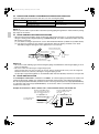
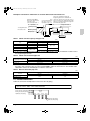
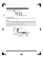
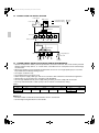
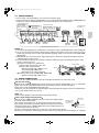
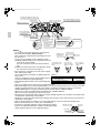
00_CV_3P194121-4J.fm Page 1 Saturday, May 23, 2009 2:44 PM
INSTALLATION MANUAL
English
III SYSTEM Air Conditioners
Deutsch
MODELS
〈BS unit〉
BSV4Q100PV1
BSV6Q100PV1
Français
Español
Italiano
READ THESE INSTRUCTIONS CAREFULLY BEFORE INSTALLATION.
KEEP THIS MANUAL IN A HANDY PLACE FOR FUTURE REFERENCE.
LESEN SIE DIESE ANWEISUNGEN VOR DER INSTALLATION SORGFÄLTIG DURCH.
BEWAHREN SIE DIESE ANLEITUNG FÜR SPÄTERE BEZUGNAHME GRIFFBEREIT AUF.
LIRE SOIGNEUSEMENT CES INSTRUCTIONS AVANT L’INSTALLATION.
CONSERVER CE MANUEL A PORTEE DE MAIN POUR REFERENCE ULTERIEURE.
LEA CUIDADOSAMENTE ESTAS INSTRUCCIONES ANTES DE INSTALAR.
GUARDE ESTE MANUAL EN UN LUGAR A MANO PARA LEER EN CASO DE TENER
ALGUNA DUDA.
PRIMA DELL’INSTALLAZIONE LEGGERE ATTENTAMENTE QUESTE ISTRUZIONI.
TENERE QUESTO MANUALE A PORTATA DI MANO PER RIFERIMENTI FUTURI.
ÄΙΑΒΑΣΤΕ ΠΡΟΣΕΚΤΙΚΑ ΑΥΤΕΣ ΤΙΣ ΟÄΗΓΙΕΣ ΠΡΙΝ ΑΠΟ ΤΗΝ ΕΓΚΑΤΑΣΤΑΣΗ ΕΧΕΤΕ ΑΥΤΟ
ΤΟ ΕΓΧΕΙΡΙÄΙΟ ΕΥΚΑΙΡΟ ΓΙΑ ΝΑ ΤΟ ΣΥΜΒΟΥΛΕΥΕΣΤΕ ΣΤΟ ΜΕΛΛΟΝ.
LEES DEZE INSTRUCTIES ZORGVULDIG DOOR VOOR INSTALLATIE. BEWAAR DEZE HANDLEINDING WAAR U HEM KUNT TERUGVINDEN VOOR LATERE NASLAG.
LEIA COM ATENÇÃO ESTAS INSTRUÇÕES ANTES DE REALIZAR A INSTALAÇÃO.
MANTENHA ESTE MANUAL AO SEU ALCANCE PARA FUTURAS CONSULTAS.
ПЕРЕД НАЧАЛОМ МОНТАЖА ВНИМАТЕЛЬНО ОЗНАКОМЬТЕСЬ С ДАННЫМИ
ИНСТРУКЦИЯМИ. СОХРАНИТЕ ДАННОЕ РУКОВОДСТВО В МЕСТЕ, УДОБНОМ ДЛЯ
ОБРАЩЕНИЯ В БУДУЩЕМ.
MONTAJDAN ÖNCE BU TALÝMATLARI DÝKKATLÝ BÝR BÝÇÝMDE OKUYUN.
GELECEKTE BAÞVURMAK ÜZERE BU ELKÝTABINI KOLAY ULAÞABÝLECEÐÝNÝZ BÝR YERDE
MUHAFAZA EDÝN.
ÅëëçíéêÜ
Nederlands
Portugues
Ðóññêèé
EN60335-2-40,
Shinri Sada
Manager Quality Control Department
1st of Mar. 2009
Umeda Center Bldg., 2-4-12, Nakazaki-Nishi,
Kita-Ku, Osaka, 530-8323 Japan
0510260101
TÜV Rheinlard EPS B.V.
DAIKIN.TCF.024D11/02-2009
REYQ8PY1, REYQ10PY1, REYQ12PY1, REYQ14PY1, REYQ16PY1,
REYQ18PY1, REYQ20PY1, REYQ22PY1, REYQ24PY1, REYQ26PY1, REYQ28PY1, REYQ30PY1, REYQ32PY1,
REYQ34PY1, REYQ36PY1, REYQ38PY1, REYQ40PY1, REYQ42PY1, REYQ44PY1, REYQ46PY1, REYQ48PY1,
REYQ8PY1B, REYQ10PY1B, REYQ12PY1B, REYQ14PY1B, REYQ16PY1B,
REMQ8PY1, REMQ10PY1, REMQ12PY1, REMQ14PY1, REMQ16PY1,
BSVQ100PV1, BSVQ160PV1, BSVQ250PV1, BSV4Q100PV1, BSV6Q100PV1,
REYQ8P8Y1B, REYQ10P8Y1B, REYQ12P8Y1B, REYQ14P8Y1B, REYQ16P8Y1B,
RWEYQ8PY1, RWEYQ10PY1, RWEYQ16PY1, RWEYQ18PY1, RWEYQ20PY1, RWEYQ24PY1, RWEYQ26PY1, RWEYQ28PY1, RWEYQ30PY1,
Low Voltage 2006/95/EC
Machinery Safety 98/37/EC
Electromagnetic Compatibility 2004/108/EC
RXYQ5PY1(E), RXYQ8PY1(E), RXYQ10PY1(E), RXYQ12PY1(E), RXYQ14PY1(E), RXYQ16PY1(E), RXYQ18PY1(E),
RXYQ20PY1(E), RXYQ22PY1(E), RXYQ24PY1(E), RXYQ26PY1(E), RXYQ28PY1(E),
RXYQ30PY1(E), RXYQ32PY1(E), RXYQ34PY1(E), RXYQ36PY1(E), RXYQ38PY1(E),
RXYQ40PY1(E), RXYQ42PY1(E), RXYQ44PY1(E), RXYQ46PY1(E), RXYQ48PY1(E),
RXYQ50PY1(E), RXYQ52PY1(E), RXYQ54PY1(E),
RTSYQ10PY1, RTSYQ14PY1, RTSYQ16PY1, RTSYQ20PY1,
RTSQ8PY1, RTSQ10PY1, RTSQ12PY1, RTSQ14PY1, RTSQ16PY1,
BTSQ20PY1,
DAIKIN INDUSTRIES, LTD.
3P216950-1D.fm Page 1 Tuesday, March 31, 2009 1:44 PM
3P216950-1D
01_EN_3P194121-4J.fm Page 1 Wednesday, June 10, 2009 12:39 PM
BSV4Q100PV1
BSV6Q100PV1
VRVIII SYSTEM Air Conditioners
Installation manual
CONTENTS
1
2
3
4
5
6
7
8
9
SAFETY PRECAUTIONS...............................................................................................1
BEFORE INSTALLATION ..............................................................................................3
SELECTING INSTALLATION SITE................................................................................5
PREPARATIONS BEFORE INSTALLATION .................................................................5
BS UNIT INSTALLATION...............................................................................................6
REFRIGERANT PIPING WORK ....................................................................................7
ELECTRIC WIRING WORK .........................................................................................11
INITIAL SETTING.........................................................................................................15
CHECK OPERATION AND TEST OPERATION..........................................................15
1. SAFETY PRECAUTIONS
Please read these “SAFETY PRECAUTIONS” carefully before installing air conditioning unit and be sure to
install it correctly. After completing the installation, make sure that the unit operates properly during the startup operation. After completing installation, conduct a trial operation to check for faults. Inform customers that
they should store this installation manual for future reference.
This air conditioner comes under the term “appliances not accessible to the general public”.
BS unit is a class A product. In a domestic environment this product may cause radio interference in which
case the user may be required to take adequate measures.
Meaning of WARNING and CAUTION notices
WARNING .........Failure to follow these instructions properly may result in personal injury or loss of life.
CAUTION ..........Failure to observe these instructions properly may result in property damage or personal injury, which may be serious depending on the circumstances.
•
•
•
•
•
•
WARNING
Ask your dealer or qualified personnel to carry out installation work.
Do not attempt to install the air conditioner yourself. Improper installation may result in water leakage,
electric shocks or fire.
Install the air conditioner in accordance with the instructions in this installation manual.
Improper installation may result in water leakage, electric shocks or fire.
Consult your local dealer regarding what to do in case of refrigerant leakage.
When the air conditioner is to be installed in a small room, it is necessary to take proper measures so that
the amount of any leaked refrigerant does not exceed the concentration limit in the event of a leakage. Otherwise, this may lead to an accident due to oxygen depletion.
Be sure to use only the specified accessories and parts for installation work.
Failure to use the specified parts may result in the unit falling, water leakage, electric shocks or fire.
Install the air conditioner on a foundation strong enough to withstand the weight of the unit.
A foundation of insufficient strength may result in the equipment falling and causing injury.
Carry out the specified installation work after taking into account earthquakes.
Failure to do so during installation work may result in the unit falling and causing accidents.
English
1
01_EN_3P194121-4J.fm Page 2 Wednesday, June 10, 2009 12:39 PM
• Make sure that a separate power supply circuit is provided for this unit and that all electrical work is carried
out by qualified personnel according to local laws and regulations and this installation manual.
An insufficient power supply capacity or improper electrical construction may lead to electric shocks or fire.
• Be sure to earth the air conditioner.
Do not earth the unit to a utility pipe, lightning conductor or telephone earth lead. Imperfect earthing may
result in electric shocks or fire.
A high surge current from lightning or other sources may cause damage to the air conditioner.
• Be sure to install an earth leakage breaker.
Failure to install an earth leakage breaker may result in electric shocks or fire.
• Be sure to switch off the unit before touching any electrical parts.
• Make sure that all wiring is secured, the specified wires are used, and that there is no strain on the terminal
connections or wires.
Improper connections or securing of wires may result in abnormal heat build-up or fire.
• When wiring the power supply and connecting the wiring between the indoor and outdoor units, position the
wires so that the EL. COMPO. BOX lid can be securely fastened.
Improper positioning of the EL. COMPO. BOX lid may result in electric shocks, fire or overheating terminals.
• If refrigerant gas leaks during installation, ventilate the area immediately.
Toxic gas may be produced if the refrigerant gas comes into contact with fire.
• After completing installation, check for refrigerant gas leakage.
Toxic gas may be produced if the refrigerant gas leaks into the room and comes into contact with a source
of fire, such as a fan heater, stove or cooker.
• Do not directly touch refrigerant that has leaked from refrigerant pipes or other areas, as there is a danger
of frostbite.
•
CAUTION
Install the BS units, power cord and connecting wires at least 1 meter away from televisions or radios to prevent picture interference and noise.
(Depending on the incoming signal strength, a distance of 1 meter may not be sufficient to eliminate noise.)
Remote controller (wireless kit) transmitting distance can be shorter than expected in rooms with electronic
fluorescent lamps (inverter or rapid start types).
Install the BS unit as far away from fluorescent lamps as possible.
Make sure to provide for adequate measures in order to prevent that the outdoor unit be used as a shelter
by small animals.
Small animals making contact with electrical parts can cause malfunctions, smoke or fire. Please instruct
the customer to keep the area around the unit clean.
Do not install the air conditioner in the following locations:
1. Where there is a high concentration of mineral oil spray or vapour (e.g. a kitchen).
Plastic parts will deteriorate, parts may fall off and water leakage could result.
2. Where corrosive gas, such as sulphurous acid gas, is produced.
Corroding of copper pipes or soldered parts may result in refrigerant leakage.
3. Near machinery emitting electromagnetic radiation.
Electromagnetic radiation may disturb the operation of the control system and result in a malfunction of
the unit.
4. Where flammable gas may leak, where there is carbon fibre or ignitable dust suspensions in the air, or
where volatile flammables such as paint thinner or gasoline are handled.
Operating the unit in such conditions may result in fire.
5. Do not use in areas where the air is salty, such as along seacoasts, in factories or other areas with significant voltage fluctuations, or in automobiles and watercraft.
Doing so could result in a malfunction.
The BS unit is not intended for use in a potentially explosive atmosphere.
2
English
•
•
•
•
01_EN_3P194121-4J.fm Page 3 Wednesday, June 10, 2009 12:39 PM
CAUTION
The refrigerant R410A requires that strict precautions be observed for keeping the system clean, dry
and tightly sealed.
Clean and dry
Strict measures must be taken to keep impurities (including SUNISO oil and other mineral oils as well as
moisture) out of the system.
Tightly sealed
R410A contains no chlorine, does not destroy the ozone layer and so does not reduce the earth’s protection against harmful ultraviolet radiation. R410A will contribute only slightly to the greenhouse effect
if released into the atmosphere. Therefore, sealing tightness is particularly important in installation.
Carefully read the chapter “REFRIGERANT PIPING WORK” and strictly observe the correct procedures.
Disposal requirements
Dismantling of the unit, treatment of the refrigerant, of oil and of other parts must be done in accordance
with relevant local and national legislation.
2. BEFORE INSTALLATION
2-1 CAUTION CONCERNING NEW REFRIGERANT SERIES
• Since design pressure is 4.0 MPa or 40 bar (for R407C units: 3.3 MPa or 33 bar), the thickness of pipes
must be greater than previously. Since R410A is a mixed refrigerant, the required additional refrigerant
must be charged in its liquid state. (If the system is charged with refrigerant in its gaseous state, due to composition change, the system will not function normally.)
The indoor/outdoor unit is designed for R410A use. See the catalogue for indoor/outdoor unit models that
can be connected.
(Normal operation is not possible when connecting units that are originally designed for other refrigerants.)
2-2 PRECAUTIONS
• Hold the unit by the Hanging brackets (4 points) when opening the box and moving it, and do not lift it holding on to any other part especially the refrigerant piping.
• About installation of outdoor and indoor unit, refer to the installation manual provided with the outdoor and
the indoor unit.
• This unit, both indoor and outdoor, is suitable for installation in a commercial and light industrial environment.
If installed as a household appliance it could cause electromagnetic interference.
2-3 ACCESSORIES
Check the following accessories are included with your unit.
NOTE
• Do not throw away any of the accessories until installation is complete.
〈BSV4Q100PV1〉
Name
Quantity
1) Accessory pipes
4 pcs.
1)-1
4 pcs.
1)-2
2) Clamp
12 pcs.
2)-1
3) Insulation tube
16 pcs.
2)-2
4 pcs.
3)-1
4 pcs.
1 copy
3)-2
Installation
manual
Shape
φ9.5
English
Explanation
Document
φ15.9
(Small)
(Large)
(Small)
(Large)
3
01_EN_3P194121-4J.fm Page 4 Wednesday, June 10, 2009 12:39 PM
〈BSV6Q100PV1〉
Name
Quantity
1) Accessory pipes
6 pcs.
1)-1
2) Clamp
6 pcs.
1)-2
16 pcs.
2)-1
3) Insulation tube
24 pcs.
6 pcs.
2)-2
Explanation
Document
6 pcs.
3)-1
1 copy
3)-2
Installation
manual
Shape
φ9.5
φ15.9
(Small)
(Large)
(Small)
(Large)
* • A reducing joint (field supply) will be required if the on-site piping diameter specified in the installation
manual for the outdoor unit or in the relevant Engineering data book differs from the piping diameter on the
outdoor unit side of the BS unit.
* • The insulation material on the outdoor unit side is a field supply.
2-4 COMBINATION
• This BS unit is only for systems for Models REYQ-P and RWEYQ-P.
It cannot be connected to systems for Models REYQ-M.
• For series of applicable indoor units, refer to the catalog or other literature.
• Select the BS unit to fit the total capacity (sum of unit’s capacity) and max. number of the indoor units to be
connected downstream, refer to the Table 1. About indoor unit’s capacity, refer to the Table 2.
Table 1
Model
Total capacity of all downstreem indoor units
Max. number of all downstreem indoor units
BSV4Q100PV1
A ≤ 400
(*)
20
(*)
BSV6Q100PV1
A ≤ 600
(*)
30
(*)
* The total capacity and number of indoor units connectable to each branch connector are up to 100 and 5,
respectively.
Table 2
Capacity expressed as indoor unit’s model No.
20
25
32
40
50
63
80
100
Indoor unit’s capacity (for use in computation)
20
25
31.25
40
50
62.5
80
100
* About indoor unit’s capacity for HRV type (VKM), refer to the Engineering data book.
<Example>
In case of the BS unit witch connect a FXCQ32M and a FXSQ40M.
Total capacity = 31.25+40 = 71.25
2-5 CHECK ITEM
• For the following items, take special care during construction and check after installation is finished.
Completion check items
Check items
Problems
Are the BS units installed securely?
Falling, vibration, and operating noise
Have you performed a gas leak test?
Does not cool or heat
Is the insulation complete? (Refrigerant piping and pipe connection part)
Water leaking
Is the voltage the same as that listed on the unit’s nameplate?
Does not operate/burnt out
Are all the wiring and piping correct?
Does not operate/burnt out
Is the unit grounded?
Dangers during electrical leak
Is the thickness of the power cord as specified?
Does not operate/burnt out
Check
Hand-over check items
Check items
Check
Did you close the EL. COMPO. BOX lid?
Did you hand the operating manual and warranty card to the customer?
Are the transmission wiring and piping lines of each unit not connected in reverse?
4
English
01_EN_3P194121-4J.fm Page 5 Wednesday, June 10, 2009 12:39 PM
3. SELECTING INSTALLATION SITE
Select an installation site where the following conditions are satisfied and that meets with your customer’s
approval.
• Where is resistible against weight of BS unit.
• Locations where the wall is not significantly tilted.
• Where sufficient clearance for maintenance and service can be ensured. (Refer to Fig. 1, Fig. 2)
• Locations where an inspection hole (Refer to Fig. 1) can be installed to EL. COMPO. BOX side (*1).
• Where the total piping length involving indoor unit and outdoor unit is below the allowable piping length.
(See installation manual attached to outdoor unit.)
• Where the sound of passing refrigerant does not cause problems. Never install the BS unit on the opposite
side of the ceiling of the living room.
(mm)
Top of
BS unit
300 or
more
300 or
more
Top of
BS unit
300 or
more
450(*1)
In the case of BSV4Q100PV1
Inspection hole
Indoor
unit side
(two pipes)
450(*1)
In the case of BSV6Q100PV1
Fig. 1
50 or
more
Inspection hole
(600)(*3)
(600)(*3)
250 or
more
300 or
more
(mm)
(*2)
Fig. 2
(*1) Be sure to install the inspection hole on the EL. COMPO. BOX side. Another opening is required in the case of taking down
the product.
(*2) Secure the service space for the local piping.
(*3) The space is required to locate the top plate of the BS unit at the time of servicing.
NOTES
• Study if the installation location is strong enough to hold the weight of the unit, and if necessary reinforce
the area with a beam or other member and then install suspension bolts. Use the suspension bolts to install
the unit. (Refer to “4. PREPARATIONS BEFORE INSTALLATION”)
• Install the BS unit and its power cord and connecting wires at least 1 meter away from televisions and radios
to prevent picture interference and noise. (Depending on the incoming signal strength, a distance of 1 meter
may not be sufficient to eliminate noise.)
4. PREPARATIONS BEFORE INSTALLATION
Refer the figure 3 and install the suspension bolts and hanging brackets.
〈Suspension bolts: For supporting the product〉
• Use M8-M10 suspension bolts.
• When holes are to be made anew, used embedded inserts and embedded foundation bolts. When holes
are already provided, use hole-in-anchors or the like.
Install the BS unit so that its weight can be withstood.
English
5
01_EN_3P194121-4J.fm Page 6 Wednesday, June 10, 2009 12:39 PM
〈Hanging bracket: For supporting the connection pipe〉
• Be sure to support the connection piping around the unit using hanging brackets that are kept within
1 meter of the body side surface. Hanging excessive weight on the BS unit hanging bracket could cause the
unit to fall and injure someone.
A
495
(mm)
BS unit
BSV4Q100PV1
BSV6Q100PV1
A
1102
1626
<Suspension bolt pitch>
Slab
Hanging
bracket
Unit proper
1m or less
Anchor
Long nut or
turnbuckle
Suspension
bolt
1m or less
Note: All the above parts are part to be procured in the field.
<Example installation>
Fig. 3
5. BS UNIT INSTALLATION
Use only accessories and parts which are of the designated specification when installing.
(1) Attach the hooks to the suspension bolts.
Be sure to use the nuts (M8 or M10: 3 pcs, 4 locations) and washers
(For M8: Outside diameter dimension 24 to 28mm, For M10: Outside
diameter 30 to 34mm: 2 pcs, 4 locations) (field supply) from both the
top and bottom sides of the hanging bracket and make sure they are
tightened correctly.
Washer
(Field supply)
Nut
(Field supply)
Hanging
bracket
10 – 15mm
Nut
(Double nut)
(Field supply)
BS unit
proper
NOTES
Suspension bolt
• The BS unit has a top and a bottom, so install it so that the diagonal
(Field supply)
lines in the figure 4 are where the top is.
(Failing to do so may prevent the unit from operating properly and increase the volume of the operating
noise.)
Fig. 4
6
English
01_EN_3P194121-4J.fm Page 7 Wednesday, June 10, 2009 12:39 PM
6. REFRIGERANT PIPING WORK
• For instruction for installing piping between the outdoor unit and BS unit, selecting a refrigerant branch kit,
and installing piping between the refrigerant branch kit and the indoor unit, refer to the installation manual
and equipment design materials included with the outdoor unit.
• Before beginning the work, always check to make sure the type of refrigerant used is R410A. (The unit will
not operate correctly with a different type of refrigerant.)
• Insulate all of the piping including the liquid pipes, HP/LP gas pipes, suction gas pipes, gas pipes, and the
pipe connections for these. Not insulting these pipes could result in water leaks or burns. In particular, suction gas flows in the HP/LP gas piping during full cooling operation, so the same amount of insulation as
used for the suction gas piping is required. In addition, high-pressure gas flows in the HP/LP gas piping and
gas piping, so use insulation that can withstand more than 120°C.
• Reinforce the insulation material when necessary for the installation environment. Refer to the following as
a guideline.
• For 30°C, RH75% to 80%: Thickness at least 15mm
• For 30°C, over RH80%: Thickness at least 20mm
If not reinforced, condensation could form on the surface of the insulation. For details, refer to the Engineering data book.
NOTES
• This product only uses the new refrigerant (R410A). Be sure to use the special pipe cutters for R410A, during installation.
• Make sure that nothing besides the specified refrigerant, such as air, gets into the refrigerant piping.
• If refrigerant gas leaks during the work, ventilate the area. (The outdoor units are filled with refrigerant.)
6-1 PIPING MATERIAL SELECTION
• Use only pipes which are clean inside and outside and which do not accumulate harmful sulfur, oxidants,
dirt, cutting oils, moisture, or other contamination. (Foreign materials inside pipes including oils for fabrication must be 30mg/10m or less.)
• Use the following items for the refrigerant piping.
Material: Jointless phosphor-deoxidized copper pipe
Size: See “Example of connection” to determine the correct size.
Thickness: Select a thickness for the refrigerant piping which complies with national and local laws.
For R410A, the design pressure is 4.0 MPa (40bar).
The minimum thickness of piping according to Japan’s High-Pressure Gas Safety Law (as of January
2003) is shown below.
Temper grade (O type, 1/2H type) in the table indicate the material types specified in JIS H 3300.
(mm)
Temper grade
O type
outer diameter
φ6.4
φ9.5
φ12.7
φ15.9
smallest thickness
0.80
0.80
0.80
0.99
(mm)
Temper grade
1/2H type
outer diameter
φ19.1
φ22.2
φ25.4
φ28.6
φ31.8
φ34.9
φ38.1
φ41.3
smallest thickness
0.80
0.80
0.88
0.99
1.10
1.21
1.32
1.43
• For information regarding the piping allowable maximum length, allowable height difference, and allowable
length after a branch, refer to the installation manual that came with the outdoor unit or Engineering data
book.
• The refrigerant branch kit (sold separately) is required for piping branches. For information on how to select
a refrigerant branch kit, refer to the Installation Manual that came with the outdoor unit or Engineering data
book.
English
7
01_EN_3P194121-4J.fm Page 8 Wednesday, June 10, 2009 12:39 PM
6-2 PROTECTION AGAINST CONTAMINATION WHEN INSTALLING PIPES
Protect the piping to prevent moisture, dirt, dust, etc. from entering the piping.
Place
Outdoor
Indoor
Installation period
Protection method
More than a month
Pinch the pipe
Less than a month
Pinch or tape the pipe
Regardless of the period
NOTE
Exercise special caution to prevent dirt or dust when passing piping through holes in walls and when passing
pipe edges to the exterior.
6-3 PIPING CONNECTION WORK PRECAUTIONS
• When brazing refrigerant piping, begin working after replacing the nitrogen (*1) or perform brazing while
nitrogen is flowing in the refrigerant piping (*2) (Refer to Fig. 5), and at the end made the indoor unit and
BS unit flare connection.
(*1) For details on nitrogen replacement, see the “VRV Installation Manual” (available at any Daikin dealer).
(*2) The pressure regulator for the nitrogen released when doing the brazing should be set to about
2
0.02 MPa (0.2kg/cm :Enough to feel a slight breeze on your cheek).
Pressure-reducing valve
Part to be brazed
Taping
Nitrogen
Nitrogen
Valve
Refrigerant piping
Fig. 5
NOTES
• Do not use an anti-oxidizing agent when brazing the piping. Residual debris could clog the piping or cause
parts to malfunction.
• Do not use a flux when brazing the refrigerant pipe joints.
Using a chlorine flux may cause the pipes to corrode, and if it contains fluoride it may cause the refrigerant
lubricant to deteriorate, adversely affecting the refrigerant piping system.
Use phosphor copper brazing (BCuP-2: JIS Z 3264/B-Cu93P-710/795: ISO 3677) which does not require flux.
6-4 PIPING SIZE SELECTION
From Example of connection 1 and 2 below and Table 1, 2, select the piping size between the outdoor unit
(refrigerant branch kit) and BS unit, and between the BS unit and the indoor unit (refrigerant branch kit).
The closed pipe kit (KHFP26A100C) should be used for selecting reluctantly 6-branch type (BSV6Q100PV1)
as 5-branches and 4-branch type (BSV4Q100PV1) as 3 branches, and it is connected to the branch not connected for the indoor unit.
Example of connection 1: When 1 indoor unit is connected downstream from the BS unit
Select from Table 2 depending
on the capacity type of the
indoor unit.
<Upstream>
<Downstream>
Suction gas pipe
*2
Gas
pipe
HP/LP gas pipe
Liquid pipe
8
BS
unit
Liquid
pipe
To refrigerant branch
kit or outdoor unit
Determine using Table 1 based
on the total capacity of the indoor
units connected downstream. *1
Indoor unit
<Downstream>
English
01_EN_3P194121-4J.fm Page 9 Wednesday, June 10, 2009 12:39 PM
Example of connection 2: When there is a branch downstream from the BS unit
(mm)
Use the following pipes:
Gas pipe: φ15.9 × 1.0
Liquid pipe: φ9.5 × 0.8
Determine using Table 1
based on the total capacity
of the indoor units
connected downstream. *1
<Upstream>
Suction gas pipe
Refrigerant branch kit
<Downstream>
BS
unit
HP/LP gas pipe
Liquid
pipe
Liquid pipe
Gas
pipe
To refrigerant branch
kit or outdoor unit
Refer to the installation manual and
Engineering data book included with the
outdoor it to decide on the respective sizes of
pipes connecting to the refrigerant branch kits
and those connecting between the refrigerant
branch kits and indoor units.
Indoor unit
Indoor unit
Indoor unit
Table 1 Indoor unit total capacity and pipe size
(mm)
Piping size (outer diameter × minimum thickness)
Indoor capacity index
(Q)
Suction gas pipe
HP/LP gas pipe
Q < 150
φ15.9 × 0.99
φ12.7 × 0.80
150 ≤ Q < 200
φ19.1 × 0.80
φ15.9 × 0.80
200 ≤ Q < 290
φ22.2 × 0.80
290 ≤ Q < 420
420 ≤ Q ≤ 600
Liquid pipe
φ9.5 × 0.80
φ19.1 × 0.80
φ28.6 × 0.99
φ12.7 × 0.80
φ28.6 × 0.99
φ15.9 × 0.80
*1 In the case of connection to the main pipe, refer to the installation manual provided to the outdoor unit or
the Engineering data book.
Table 2 Indoor unit connection pipe size
(mm)
Piping size (outer diameter × minimum thickness)
Capacity type of indoor units
Gas pipe
Liquid pipe
20, 25, 32, 40, 50
φ12.7 × 0.80
φ6.4 × 0.80
63, 80, 100
φ15.9 × 0.99
φ9.5 × 0.80
*2 The BS unit downstream connection pipe sizes are shown below. If the pipe diameter differs from that of
the indoor unit connection pipe size selected from Table 2, follow the instructions in “6-5 PIPING CONNECTION” and use the included pipe to make the connection.
Table 3 BS unit connection pipe size
(mm)
Piping size (outer diameter)
BS unit
BSV4Q100PV1
BSV6Q100PV1
Gas pipe
Liquid pipe
φ15.9
φ9.5
6-5 PIPING CONNECTION
Follow the connection example below and connect the site piping.
When the downstream indoor unit total capacity is 100 or less and when one indoor unit with
a capacity of 63 to 100 is connected downstream.
Suction gas pipe (Site piping)
BS unit
(Top)
HP/LP gas pipe (Site piping)
Liquid pipe (Site piping)
Unit D
Unit C
Unit B
Unit A
Gas pipe (Site piping)
Liquid pipe (Site piping)
English
9
01_EN_3P194121-4J.fm Page 10 Wednesday, June 10, 2009 12:39 PM
When one indoor unit with a capacity of 20 to 50 is connected downstream
Suction gas pipe (Site piping)
BS unit
(Top)
HP/LP gas pipe (Site piping)
Liquid pipe (Site piping)
Unit D
Unit C
Unit B
Unit A
Accessory pipes 1)-2
Gas pipe (Site piping)
Accessory pipes 1)-1
Liquid pipe (Site piping)
6-6 PIPING INSULATION
• After the gas leak inspection is completed, refer to the following figures and use the included insulation tube
3) and clamps 2) to apply the insulation.
NOTES
• Insulate all of the piping including the liquid pipes, HP/LP gas pipes, suction gas pipes, gas pipes, and the
pipe connections for these. Not insulting these pipes could result in water leaks or burns. In particular, suction gas flows in the HP/LP gas pipes during full cooling operation, so the same amount of insulation as
used for the suction gas pipes is required. In addition, high-pressure gas flows in the HP/LP gas pipes and
gas pipes, so use insulation that can withstand more than 120°C.
• When reinforcing the insulation material for the installation environment, also reinforce the insulation on the
piping protruding from the unit and on the pipe connections. Locally purchase the insulation required for the
reinforcement work.
Insulation tube
(Field supply)
Suction gas pipe
(Note 1)
HP/LP gas pipe
(Note 1)
Clamp (Field supply)
BS unit
Liquid pipe
Insulation tube
(Field supply)
Clamp 2)-2
(Accessory)
Insulation tube 3)-1
(Accessory)
Clamp (Field supply)
10
Clamp 2)-2
(Accessory)
Insulation tube 3)-2
(Accessory)
Gas pipe
(Note 1)
Liquid pipe
English
01_EN_3P194121-4J.fm Page 11 Wednesday, June 10, 2009 12:39 PM
Insulation Attachment Instructions
Two-pipe distribution side: Indoor unit connection side
Insulation Attachment Instructions
(on three-pipe side)
(1) Attach the insulation.
(Field supply)
Piping insulation
(Site piping side)
Reducer (Field supply)
(1) Attach the included
insulation.
Pipe connection
(Field supply)
Bind the insulation material with an
appropriate material, such as a tape,
so that there will be no clearance.
Piping insulation
(Product piping side)
Main unit
(3) Use the clamps (field supply)
to hold both ends.
Note 1: For suction gas pipes, HP/LP gas
pipes, and gas pipes, after
attaching the included insulation
tube, wrap more insulation (field
supply) around the connections.
Piping insulation
(Product piping side)
Pipe connection
Piping insulation
(Site piping side)
Main unit
(2) Seal
(2) Seal
(3) Use the clamps (accessory)
to hold both ends.
Insulation material
(Field supply)
Insulation Installation Precautions
1. Seal so that air cannot be in and out of the end.
2. Do not over tighten the clamp so as to maintain the insulation thickness.
3. Be sure to attach the insulation (field supply) with the seams facing up.
(See figure at right.)
Seam
Attach facing up
7. ELECTRIC WIRING WORK
7-1 GENERAL INSTRUCTIONS
•
•
•
•
•
•
•
•
•
•
All wiring must be performed by an authorized electrician.
All field supplied parts and materials, electric works must conform to local codes.
Always ground wires. (In accordance with national regulations of the pertinent country.)
Always turn off the power before performing the electric wire installation work.
Follow the “WIRING DIAGRAM” attached to the unit body to wire the outdoor unit and indoor units.
Properly connect wire of the specified wire type and copper thickness. Also use the included clamp to avoid
applying excessive force to the terminal (field wire, ground wire).
Do no let the ground wire should come in contact with gas pipes, water pipes, lighting rods, or telephone
ground wires.
• Gas pipes: gas leaks can cause explosions and fire.
• Water pipes: cannot be grounded if hard vinyl pipes are used.
• Telephone ground and lightning rods: the ground potential when struck by lightning gets extremely high.
A circuit breaker capable of shutting down the power supply to the entire system must be installed.
This system consists of multiple BS units. Mark each BS unit as unit A, unit B . . . , and be sure the terminal
board wiring to the outdoor unit and indoor unit are properly matched. If wiring and piping between the outdoor unit, BS unit and an indoor unit are mismatched, the system may cause a malfunction.
Do not turn on the power supply (branch switches, overload interrupters) until all other work is done.
English
11
01_EN_3P194121-4J.fm Page 12 Wednesday, June 10, 2009 12:39 PM
7-2 EXAMPLE FOR THE WHOLE SYSTEM
Power supply
Outdoor unit
Power supply wiring
Main
switch
Power supply
Transmission wiring
Switch
Fuse
Main
switch
BSV4Q unit
Indoor unit
Remote controller
BSV4Q unit
Indoor unit
Cooling-dedicated
indoor unit
Remote
controller
Remote
controller
7-3 POWER CIRCUIT, SAFETY DEVICE AND CABLE REQUIREMENTS
• A power circuit (Refer to Table 3) must be provided for connection of the unit. This circuit must be protected
with the required safety devices, i.e. a main switch, a slow blow fuse on each phase and an earth leakage
circuit breaker.
• When using residual current operated circuit breakers, be sure to use a high-speed type (0.1 second or
less) 30mA rated residual operating current.
• Use copper conductors only.
• Use insulated wire for the power cord.
• Select the power supply cable type and size in accordance with relevant local and national regulations.
• Specifications for local wiring are in compliance with IEC60245.
• Use wire type H05VV-U3G for power supply wiring. And the size must comply with local codes.
2
• Use vinyl cord with sheath or cable (2 wire) of 0.75-1.25mm for transmission wiring.
Table 3
Units
Model
BSV4Q100P
BSV6Q100P
Type
V1
MCA: Min. Circuit Amps (A);
Hz
50
Voltage
220-240
Power supply
Min.
198
Max.
264
MCA
0.5
0.8
MFA
15
MFA: Max. Fuse Amps (A)
NOTES
• The above Table 3 of Electrical Characteristics refers to one BS unit.
• See the Engineering data book for other details.
12
English
01_EN_3P194121-4J.fm Page 13 Wednesday, June 10, 2009 12:39 PM
7-4 WIRING EXAMPLE
• Here is shown a wiring example for one system transmission wiring.
• Connect terminals F1 and F2 (TO IN/D UNIT) on the control PCB in the outdoor unit EL. COMPO. BOX and
terminals F1 and F2 (TO OUT/D UNIT) of the control PCB (A1P) of the first BS unit A.
COOL/HEAT SELECTOR wiring
Transmission wiring
Absolutely do not
connect the power
supply wiring.
Use 2-core wires.
(There is no polarity.)
IN / OUT OUT / OUT
F1 F2 F1 F2
C/H SELECTOR
C B A
PC board
Indoor
unit A
F1 F2
C/H SELECTOR
C B A
PC board
Indoor
unit B
F1 F2
C/H SELECTOR
C B A
BS unit B
PC board
Indoor
unit C
F1 F2
C/H SELECTOR
C B A
F1 F2
F1 F2
F1 F2
Indoor unit
Indoor unit
Indoor unit
COOL/HEAT
SELECTOR
COOL/HEAT
SELECTOR
COOL/HEAT
SELECTOR
Indoor
unit D
F1 F2
F1 F2
Outdoor
BS unit
unit
F1 F2 F1 F2
F1 F2
Indoor unit
COOL/HEAT
SELECTOR
TO IN/D UNIT TO OUT/D UNIT
F1 F2 F1 F2
F1 F2
Final BS unit
A
TO IN/D UNIT TO OUT/D UNIT
F1 F2 F1 F2
B
C
F1 F2
Indoor unit
Indoor unit
COOL/HEAT
COOL/HEAT
SELECTOR
SELECTOR
C/H SELECTOR
BS unit A
PC board
Cooling-dedicated
air conditioner
Outdoor unit
C/H SELECTOR
Use 3-core wires.
(There is polarity.
Match the terminal
numbers.)
A
B
C
F1 F2
F1 F2
Cooling/Heating selectable indoor unit
NOTES
1. Connect cooling-dedicated air conditioners to terminals F1 and F2 (TO OUT/D UNIT) of the final BS unit.
2. Use 2-core wire for the transmission wiring. Using a multi-core wire with 3 or more cores when two or more
indoor units are used at once could cause abnormal stoppage. (Only use 3-core wire in the COOL/HEAT
SELECTOR.)
3. Absolutely do not connect the power supply wiring to the transmission wiring terminal block. Doing so
could damage the entire system.
4. For the transmission wiring, use wire that is within the following ranges. Exceeding these limits could
cause a transmission error.
(1) Between an outdoor unit and BS unit,
Sub-branching
Between a BS unit and indoor unit, and
Between a BS unit and BS unit
F1 F2
F1 F2
F1 F2
branch
Maximum wiring length: 1000m or less
Total wiring length: 2000 or less
Branch point max: 16 branch points
F1 F2
F1 F2
F1 F2
F1 F2
(2) Between a BS unit and COOL/HEAT SELECTOR
Maximum wiring length: 500m or less
7-5 WIRING CONNECTIONS
Remove the EL. COMPO. BOX lid on the side and follow the directions to connect the wires.
〈Transmission wiring〉
Remove the EL. COMPO. BOX lid and connect the wires to F1 and F2 (TO IN/D UNIT: A~F) , F1 and F2 (BS
UNIT) and F1 and F2 (TO OUT/D UNIT) transmission wiring terminals (control PCB (A1P)).
Indoor units E and F are BSV6Q models (PV1 only)
At this time, pass the wiring into the unit through the wiring through hole (right) and use the included clamps
2) to securely hold the wires (in 2 places).
NOTE
Check that the piping line coincides with the transmission wiring.
〈Power supply wiring and ground wire〉
Cup washer
Remove the EL. COMPO. BOX lid and connect the power supply wiring to
Ring-type crimp
the power terminal block (X1M).
style terminal
Also connect the ground wire to the ground wire terminal. Pass both the
power supply wire and the ground wire together through the wire through
Cut out section
hole (left) and into the EL. COMPO. BOX and use the included clamps 2) to
securely hold the wires (in 2 places).
Be sure to wire the ground wire so that comes out of the slit in the cup washer.
(Not doing so could cause insufficient ground wire contact and causing the wire not to function as a ground.)
English
13
01_EN_3P194121-4J.fm Page 14 Wednesday, June 10, 2009 12:39 PM
Transmission wiring from indoor unit
(to F1 and F2 terminals of indoor unit)
Terminal block
Clamp 2)-1 (Accessory)
Transmission wiring from BS unit
(to F1 and F2 terminals of BS unit)
Clamp 2)-1 (Accessory)
Power supply wiring
(to P1 and S terminals
of terminal block)
Wiring through hole
Ground wire
Ground terminal
Transmission wiring
from outdoor unit
(to F1 and F2 terminals
of outdoor unit)
Wire
Wire fitting
Clamp 2)-1
(Accessory)
Transmission wiring
from indoor unit
(to F1 and F2 terminals
of indoor unit)
Clamp 2)-1 (Accessory)
Clamp 2)-1 (Accessory)
Liquid side pipe
Transmission wiring to
indoor unit (to F1 and F2
terminals on indoor side)
Rear side
NOTES
• Use ring-type crimp style terminal for connections to
Insulation sleeve
Ring-type crimp
the power terminal block. (Refer to Fig. 6)
Electric wire
style terminal
Also, insulate the crimped area by attaching an insulation sleeve, etc.
If these are not available, see the following section.
Fig. 6
(a)Wiring of different thicknesses cannot be connected
to the power terminal block.
Connect wires of the
Do not connect
Do not connect
same gauge to both
wires of the same
wires of different
(A loose connection could cause abnormal heatsides.
gauge to one side.
gauges.
ing.)
(b)When connecting wire of the same diameter, make
the connection as shown in the figure 7.
• Do not finish the conductive part of the power supply
wires with lead-tin solder.
Fig. 7
• Use an appropriate screwdriver for tightening the terTable 4
minal screw.
Terminal screw size
Tightening torque (N/m)
Using a screwdriver that is too small could damage the M3.5 (COOL/HEAT SELECTOR/transmission
0.80-0.96
wiring terminal block)
screw head and prevent proper tightening.
1.18-1.44
• Over tightening the terminal screw could damage the M4 (Power supply terminal block)
M4 (Ground terminal)
1.52-1.86
screw.
Refer to the Table 4 for the terminal screw tightening torque.
• When fastening the wire, use the included clamp 2)-1 so as not to apply tensile force to the wire connection
and then securely fasten the wire. Also, after wiring is completed, organize the wiring so that the EL.
COMPO. BOX lid does not pop up and then properly replace the EL. COMPO. BOX lid.
Make sure no wires are pinched when replacing the EL. COMPO. BOX lid.
Always use the wire through hole to protect the wires.
• Do not pass the transmission wiring and power supply wiring through the same locations and outside of the
unit keep them separated by at least 50mm.
Not doing so could cause the transmission wiring to pick up electric noise (external noise) and result in a
malfunction or breakdown.
• After the wiring working is complete, use sealer (field supply) to seal closed the wire through hole.
(Entry by small animals, etc., could cause a malfunction.)
• As shown on the right-hand side, wrap the transmission wiring
Gas pipe
Transmission wiring
between each BS unit and indoor unit with a finishing tape (field
supply) together with the on-site refrigerant piping.
Liquid pipe
Finishing tape
14
Insulation
material
English
01_EN_3P194121-4J.fm Page 15 Wednesday, June 10, 2009 12:39 PM
8. INITIAL SETTING
• When the refrigerant piping and wire installation work is completed, make the following settings as required.
1. Setting for when connecting the COOL/HEAT SELECTOR to the BS unit.
〈Setting description〉
Set the input signal from the COOL/HEAT SELECTOR (sold separately) to ON/OFF.
〈Setting method〉
Set the dip switches (DS1-1) on PCB (A1P) as shown at left before turning on the power to the BS unit.
Terminal block
(COOL/HEAT SELECTOR)
DIP switch
Turn on ON
DS1-1. OFF
DS1-1
Normal monitor for
microprocessor (HAP green)
PC board
NOTES
This setting is read by the microcomputer when the BS unit power is turned on.
• Be sure to make the setting before turning on the power.
• Always close the EL. COMPO. BOX lid after making the setting.
2. Setting when changing the “Automatic mode differential” in the Cooling/Heating Automatic Operation Mode.
〈Setting description〉
• The “Automatic mode differential” can be changed within the range of 0°C to 7°C (0°C at factory shipment).
• For details regarding the “Automatic mode differential” and indoor unit operation, refer to the “Engineering
data book”.
〈Setting method〉
The setting is made using the “Local Setting Mode” by the remote controller of indoor unit connected to the
BS unit.
For information regarding the setting method, refer to “Engineering data book”.
The following table gives a list of the “MODE NO.,” “FIRST CODE NO.,” and “SECOND CODE NO.”
NOTES
This setting is operated by the operation remote controller while the indoor unit power is turned on.
• When the indoor unit, outdoor unit, and BS unit installation work is completed, confirm that it is safe even
with the power turned on before proceeding with the work.
MODE NO.
12 (22)
FIRST CODE NO.
4
SECOND CODE NO.
Automatic mode differential (°C)
1
0
2
1
3
2
4
3
5
4
6
5
7
6
8
7
← At factory shipment.
9. CHECK OPERATION AND TEST OPERATION
(1) Check to make sure the EL. COMPO. BOX lid is closed.
(2) Refer to the installation manual provided to the outdoor unit and conduct a check and a test run after all
the work on the BS unit and outdoor and indoor units is completed and the operational safety of the units
is confirmed.
• Clicking or humming sounds will continue for about 20 sec immediately after the power is turned on due
to the start of automatic initialization operation (closing) of the solenoid valve, but this is not a problem.
English
15
00_CV_3P194121-4J.fm Page 2 Saturday, May 23, 2009 2:44 PM
3P194121-4J EM09A001A
(0907) HT