1
The XS650 Garage Carburetor Guide
Introduction
This manual has been prepared by Grizld1 (aka Dick Russell, Yamaha 650 Society
Tech Advisor) and 5twins. Material has been peer reviewed by Garage staff (thanks,
y'all!), and is as accurate as we know how to make it.
We've tried to gather the most frequently-requested information into a single reference.
In the process, we've cannibalized our own posts ruthlessly. We do not offer this guide
as the last word on XS650 carburetion; references online and in print that we've found
valuable have been recommended, and we hope you find them useful.
Please note: Directional terms (right/left, forward/back, above/below) refer to position
from the perspective of the rider in the saddle.
For ease of use, each major section below appears in a separate post.
.................................Contents
I. Tools: Post 2
II. OEM Carbs, BS38 (70-79) and BS34 (80-83): Cleaning, Adjustment, Tuning
...Post 3. Carburetor removal and installation
...Post 4. Floats and slides
...Addendum March 9, 2009 Potential Float System Defect
...Post 5. Pilot circuit
......a. pilot jets
......b. air and mixture passages
......c. mixture screws
...Post 6. Main circuit, Enricher (Choke), Synchronizing
......a. main jets
......b. needle jets and needles
......c. Enricher (choke)
......d. Synchronizing
...Post 7. Sealing Air Leaks
......a. Finding air leaks
......b. Sealing mounting boots
......c. Sealing throttle shafts
...Post 8. Tuning for Modifications
...Post 9. Troubleshooting
...Post 10. Appendix
......1. Chart, specifications
......2. Basic CV carb operation: schematic
......3. Starter system: schematic
......4. Pilot jets, comparison chart
......5. Starter pickup tube, photo
......6. BS34 Air jets, photo
......7. BS38 Air jets, photo
......8. Pilot jets and needle, photo
......9. BS38 Mix screws & vacuum ports, photo
.....10. BS34 Mix screw location, photo
.....11. Mix screw & by-pass outlets, photo
.....12. Idle & sync adjustment screws, photo
....13. BS38 Float Variations
Waning! Rebuild kits are produced cheaply to fit a variety of applications, and some
parts found in them will not be correct for your application. Always check parts against
OEM components before installing. Mike's XS is very clear about this but many vendors
are not, assuming that buyers already know. The issue isn't that rebuild kits are
defective; they're generic, and not everything in them is intended to fit every application
listed for the kits.
Post 2: TOOLS
Screwdrivers.
Jets with slotted heads are easily deformed, and problems can be avoided by grinding
screwdrivers to achieve a tight, no-slop fit in main and pilot jets. Screwdrivers and bits
with tapered blades tend to apply pressure only at the upper edges of the slot; hollow
ground screwdrivers make contact equally from top to bottom, and are less likely to
damage jets. If your carbs have float bowl plugs, main jets can be installed and
removed without removing float bowls. For BS series, use a 1/4" drive bit, ground as
above, and turn down the shank until it clears. Turn it with a 1/4" box end wrench, or
5twins' weapon of choice, a Sears finger bit driver (http://tinyurl.com/y9xar5). 5twins
also notes that Wiha 2" metric power bits in 4 mm (pilots), 6.5 mm (small round mains)
and (possibly, this is untried) 8 mm. (large round mains) are a good fit; see
www.wihatools.com For VM carbs, use a 6 mm. 1/4" drive deep socket and hex drive
adaptor for the main jets, turning with a 1/4" box end wrench. Set the screwdrivers and
bits aside for use only in carb work.
Caliper or Steel Rule.
A caliper is useful for measuring float height (see Section II. or Section III). The end of
the depth probe can be set on the carb body while the corner of the shank is sighted on
the float top. Some prefer to sight the float top with a small steel rule.
Fuel Level Sight Tube.
A direct reading of fuel level can be taken with a sight tube. Find a rubber plug to fit the
plug port in the bottom of the float bowl. Drill it and fit it with a hard plastic tube or hose
barb,and attach about 8" of clear plastic hose. Some BS-series carbs are fitted with a
drain valve in the float bowl, opened by a screw, with a nipple for a drain tube, to which
a sight tube can be attached. See Section II. for use.
Manometer (Synchronizer).
XS650's after 1976 are fitted with vacuum ports in the carb bodies, vacuum line barbs in
the mounting boots, or both. Synchronizers can be connected to either location (see
Section II. or III.)
Inexpensive dial gauges should be avoided. Mercury manometers ("mercury sticks") are
commercially available, but mercury is highly toxic and the device is easily broken.
Morgan makes the Carbtune synchronizer, employing steel rods, but it is limited in
accuracy and expensive.
A very accurate and durable tool can be made with a yardstick, 10 ft. of 3/16" clear
plastic tubing, a few ounces of automatic transmission fluid (some folks prefer 2-stroke
oil), and a pair of pilot jets (the long-pattern jets for Mikuni flat slide carbs, sizes 15 to
35, work nicely).
Loop the hose around the bottom of the yardstick and secure it with wire or twist ties so
that it runs straight up both sides; avoid pinching. Trim the ends to the same length, and
cut an 8" piece from each end. Suck ATF into the line so that it fills the tubing about 8"
high on each side. Splice the end pieces back on with the pilot jets.
Remote Fuel Bottle.
On OEM carbs with a central synchronizing screw,adjustment (see Section II.) is easiest
with the tank removed. Make a remote tank from a 1 qt. plastic bottle. Install a 1/4" hose
barb in the bottom of the bottle and a lawn mower fuel valve in the line (an in-line filter is
also a good idea). Attach a wire to the top of the bottle and hang it where you need it.
Safety note: many plastics will break down with exposure to fuel. Be sure your material
is fuel resistant, and empty the container immediately after use.
This item is not strictly necessary. 5twins recommends rough adjustment with the tank
removed, using fuel remaining in the float bowls, followed by fine adjustment with the
tank in place, reaching in with a long screwdriver. You can also set the tank on a work
bench or other elevated surface and run extensions to the carburetor lines.
Compressor
If you intend to do much mechanical work at all, an air compressor with sufficient
capacity to power an impact wrench will pay for itself quickly. For carb cleaning, attach
an air gun with a rubber tip.
©2007, , All Rights Reserved.
To the best of our knowledge, the text on this page may be freely reproduced and
distributed.
Sale of this information is prohibited.
Post 3: Stock Carb Removal and Installation
When I first got my 650, I had a difficult time getting the carb set out and had to resort to
removing the left manifold to provide enough clearance. I've since learned a few tricks
and now the removal and installation is much easier.
First, you'll want to remove the cam chain adjuster cap. This will give you more room
below the carbs. Next, and this is the biggie, remove the butterfly shaped bracket
between the carb tops (if you have one). This bracket stops the carb bank from moving
far enough to the rear to clear the intake manifolds. With it removed, the carbs will pull
back far enough to clear the manifolds and you won't have to pull one. Once clear, you
can work the set out the left side. It will take a little rolling and twisting, but they will
come out.
Now for getting the carbs in and out of the manifolds. For removal, first you'll want to
lube the boots with WD40 or silicone spray. Rock the carb bank up and spray some
lube in the bottom gap, rock it down and lube the top gap. Now rock them up and down
to distribute the lube. Once that's done, it's time to pull 'em. Use the same up and down
rocking motion as you pull back on the carbs and they should work their way right out.
For install, lube the inside of the boots and the outside of the carbs. Then use the same
rocking motion as you push them in. You'll feel a bit of a "pop" as they fully seat in. The
WD or silicone will work here for lube but Race Tech makes a seal grease (for oil seals)
that is very rubber "friendly". White lithium grease can also be used (just a thin smear don't goop it on).
If you're doing this in the dead of winter in an unheated garage or the boots are really
old and hard, you might want to heat them up a bit first with a hair dryer. I know my
carbs certainly popped into my new soft manifolds easier than they pulled out of the old
hard ones.
A note on the manifold clamps. These need to be tightened fully so the 2 clamp halves
touch, especially on new soft manifolds. These old bikes, even in a good state of tune,
sometimes spit back or backfire through the carbs, usually on start-ups. If the clamps
aren't tightened fully, the carb can pop out of the manifold. If the head of the original
phillips clamp screw is buggered up at all, you may not be able to fully tighten the clamp
so I suggest switching to allens. While the original phillips screw is longer, an M5 x 16
allen is plenty long enough for use here. ©2007, , All Rights Reserved.
To the best of our knowledge, the text on this page may be freely reproduced and
distributed.
Sale of this information is prohibited
Post 4: Slides and Floats
Slide diaphragm function can be tested as follows. If carb top screws were removed
above, reinstall them. Then look at the backs of the carburetors. At the top of each
intake bell there is a curved hole which opens into the chamber below the diaphragm,
exposing it to atmosphere. If you raise a slide, cover the port firmly with a thumb, then
release the slide, it should fall very slowly. If it falls quickly, the diaphragm is breached,
and the slide/diaphragm assembly must be replaced. Member donmurray has noted
that there is a passage from the diaphragm chamber to the enricher chamber which is
opened if the enricher cover or enricher plunger is removed. The passage must be
covered to test diaphragm integrity.
Remove the carb tops and springs and push the slides up, removing the needle
retainers and needles with them. Free the diaphragm gently. Use marked plastic bags
to keep the slides paired to their carburetors. Remove retainers and needles. Examine
each diaphragm visually for pinholes against a bright light.
Note that in addition to the hole for the needle, there is a second hole in each slide.
When the throttle is opened, air passing though the venturi (central part of the
carburetor) into the engine sweeps past this hole, creating negative pressure in the
upper part of the diaphragm chamber, which causes the slide to lift. The hole must be
clear. If it is obstructed, clear it with compressed air, probing with a wire if necessary.
Bag the marked slides and set them aside to prevent damage or contact with solvents.
To reinstall, note that each diaphragm has a "tab" that fits a matching recess in the carb
body. Be sure to align the diaphragms correctly.
The floats hang from a pin passing through two posts cast into the carb body. Care
must be taken not to damage the posts. A broken post can be repaired by carefully
drilling small matching holes in the post and the carb body and pinning the pieces
together, using JB Weld as an adhesive; but this is a touchy procedure, and damage is
entirely unnecessary. Don't try to beat the pins out!
BS38 carbs (70-79) use straight pins that fit flush with the sides of the posts. The pins
should push out. If they do not, apply a bit of spray-type carb cleaner and try to free
them. As a last resort, set a small nut against one post to relieve the end of the pin,
drive a tack through a thin piece of carpenter's shim so that the point protrudes, and use
a small C-clamp to gently press out the pin. As soon as you have movement, apply
more solvent and extract the pin with pliers. Remove the floats and float needles. Keep
float needles paired to their carburetors. If needle seats are varnished, spray with carb
cleaner and clean with Q-tips. The seat is threaded; turn CCW to remove. If needles or
seats show wear or corrosion, replace them.
BS34 carbs (80-83) use pins with flat heads and ends that protrude slightly from the
posts. They are snap-fits, and must be pressed out. Relieve the head of the pin with a
nut, press the protruding end flush with the post with a small C-clamp, and work the pin
free by prying gently under the head with a screwdriver until it can be gripped with pliers
and pulled out. The BS34 float needle is retained by a screwed-down tab, and it is
Viton-tipped; avoid contact with solvents. The BS34 seat is push-in type, sealed and
secured by an O-ring. There is a fuel screen above the needle seat in many BS34
carbs. Be sure it's clear. Clean with solvent and compressed air. Again, keep seats and
needles paired.
If the carbs have been in recent service, shake the floats. If you feel fuel sloshing in
them, replacement is the best course, although brass floats can be soldered. If the
carbs have been out of service, put the floats in a container of gas with a lid tight
enough to push them below the level of the fuel and let them sit overnight, then inspect.
Adjustment
Float level is adjusted by moving the tang that contacts the float needle. Floats must be
level (same reading on each side); this is done by adjusting the bridge between them.
Carbs must be adjusted to the same float level.
If the float bowls are fitted with drain plugs, fuel level can be inspected directly by fitting
a piece of clear hose to a plug and inserting the plug in the float bowl. Some float bowls
are fitted with drain valves opened by a screw, with a hose nipple on the outlet. To read
fuel level, attach the sight tube to the outlet and set vacuum petcocks, if fitted, on
"Prime," and open the screw until fuel flows into the sight tube. With the motorcycle
level, hold the sight tube upright beside the carburetor body. Fuel should rise in the tube
no higher than the lower lip of the carb body where it overlaps the float bowl, and no
lower than 2 mm. below it.
A second procedure is to read float height. This is measured from the surface on the
carb body on which the gasket seats to the top of the float, with the gasket removed. If
the gasket cannot be removed without damage, reduce the specification given by 1 mm.
and measure from the gasket. Holding the carburetor with the floats up, lower the floats
gently onto the float needle, taking care not to compress the float needle spring. Since
the reading is taken with the carb upside down, raising the float level will lower fuel
level, and conversely.
All BS38 carbs are set at 24 mm. +/- 1 mm.
For early BS34 carbs with brass floats, a float height of 27.3 mm. +/-1 mm. is specified.
For later units with plastic floats, 22 mm. +/-1mm. is given. The usual recommendation
is to use the specification given for the float type. All BS34 carburetors have a drain
valve at the bottom of the float bowl (see above). Fuel should rise no higher than the
lowest point of the flange on the carburetor body, and no lower than 2 mm. below that
level. ©2007, , All Rights Reserved.
To the best of our knowledge, the text on this page may be freely reproduced and
distributed.
Sale of this information is prohibited.
Addendum 3/9/2009
Member "stevesemti" has identified another potential float system defect. In pre-'78
carbs, the float chamber is vented at the bottom of the float bowl through a brass pipe
seated in the float bowl, which opens above the correct fuel level. It prevents vacuum
from forming as fuel level drops and drains off excess fuel in the event of overflow.
Steve traced a fuel leak through the vent (usually caused by float level or float valve
problems) to the seat of the vent pipe (below fuel level in the float bowl). He reports that
attempted repair with JB Weld slowed the leak but didn't stop it. Any fuel leak is a
dangerous condition. It might be possible to use a micro torch to sweat the pipe to the
seat with solder. Failing that, the float bowl should be replaced. Thanks for the headsup, Steve!
Post 5: Cleaning and Adjustment, Pilot Circuit
1. Cleaning
The most important thing to know about carb cleaning is how to avoid it in future once
you have it done. Sintered or paper in-line fuel filters will keep debris out of the
carburetors. If the bike will not be run for awhile, draining the carbs will prevent varnish
from accumulating. For extended storage, drain the carbs, lift the slides, stick a few
silica gel cylinders from an aspirin container under each slide and in the air intake
throat, and seal, to prevent condensation and corrosion.
The pilot circuit fuels the engine in low-speed operation, when the slide is lowered.
On the back of the BS38 (70-79) carburetor, you will see two small holes in the sides of
the intake bell (see Appendix, item 6). One is marked with a cast "M" on most
carburetors This is the main circuit air jet, which feeds air to the needle jet of the main
circuit. The unmarked hole is the pilot circuit air jet, which feeds air to the pilot circuit. In
BS 38 carburetors, both of these jets are fixed; nothing is removable.
In the back of the BS34 (80-83) you will find four round holes (see Appendix, item 6).
The upper pair (below curved diaphragm chamber vent) vent the carb body above the
floats. Below those are the air jets. The pilot air jet is removable, and the main air jet is
fixed.
The BS38 pilot jet seats inside the float bowl. It is the small brass fitting with a slotted
head. Above the pilot jet in the BS38 there is a recessed area in the float bowl casting,
and above that, a small hole in the carburetor body. This is where the pilot air passage
emerges after running through a tubular casting. On the other side of center, the main
air jet feeds into a similar hole and casting. In BS34 carbs the pilot jet is under a rubber
plug at the end of the smaller vertical tubular casting in the carburetor body; the plug
must seal correctly.
Use a screwdriver or bit that completely fills the slot of the jet (see Section I). If the jet
area is fairly clean and uncorroded, one sharp push-and-twist should free the jet. If jets
are fuel varnished, prep them for removal with solvent. The BS38 float bowls can be
immersed in Chem-Dip or similar solvent. In the BS34, spray-in solvent can be applied
to the jet area and followed by compressed air until varnish breaks up--never immerse
carb bodies. Apply a bit of penetrating oil and allow it to soak in. Then seat the
workpiece firmly in a padded vise or clamp, and remove the jet. Use a sharp push-and
twist motion to break the jet loose. Light taps on the screwdriver will often break a
stubborn jet free. If the slot deforms, use a screwdriver with a thicker blade or regrind
the one you're using.
Once the jets are removed, check to see that the correct series is in place. From 19701975 (XS1 through XS650B), the BS30/96 pilot jet was used. In this jet, the tightest
restriction (metering orifice) is located toward the barbed end of the jet, opposite the
threaded end. The VM22/210 jet was used from 1976-1979 XS650C-XS650F). In this
series, the metering orifice is located toward the threaded end of the jet. Either series
will thread into the carb body, and installation of incorrect jets is common. Many OEM
jets were produced with no bleed holes in the shank, while all aftermarket pilot jets have
them; this difference is not significant. See Appendix items 1., 4., and 7. for pilot jet
types and stock sizes.
Soak the jets in Chem-Dip or similar immersion-type solvent, and blow them clean with
compressed air. Blow aerosol carb cleaner through the air jets and follow with
compressed air, and do the same in the pilot jet seat areas.
On BS38 carburetors, the mixture screw is a small brass fitting with slotted head,located
on the outward side of each carburetor, forward of the slide tower (see Appendix, item
9). Remove the screws and the springs below them and clean with solvent, and blow
out the seat areas. Carbs fitted to 1970-1975 (XS1-XS650B) require the 256 series
screw; it is shorter than others, and threaded all the way to the slot. The 584 series was
used on carbs fitted in 1976 and 1977 (XS650C and D); it is longer, with a relieved area
between the slot and the threads. The screw used in carbs fitted in 1978 and 1979 is
the longest. It is stepped, has a recessed area past the slot, and is sealed by an O-ring.
The screws cannnot be interchanged. Some fuel screws were fitted with plastic caps to
restrict range of adjustment. Remove the caps and discard them.
The fuel screw in the BS34 carburetor is recessed in a vertical tubular casting on the
carb body toward the center line of each carb, forward of the slide tower (see Appendix
item 10). Unless it has been removed, the screw is covered with a thin brass cap, which
must be removed for cleaning and adjustment. Pierce the cap with a drill, being careful
not to damage the casting or the screw; just penetrate the cap. Sometimes a sheet
metal screw will hold firmly enough to grip the cap while pliers are used to extract it
(don't run the screw in deeply; avoid damage to the mixture screw beneath). Sometimes
it can be pried out after drilling. Remove the mixture screw, with the spring. A rubber Oring is at the bottom of the mixture screw seat, with a metal washer on top of it. Remove
these with a probe. When new, the washer is somewhat flattened; this does not indicate
defect. Be sure that it's flexible and has no nicks or cracks.
If fuel screws show signs of damage, wear or corrosion pits, replace them.
In the forward end of the carburetor bore, you'll find a number of holes (see Appendix,
item 11). In front of the throttle plate (butterfly), you'll find either one or two large holes
and one small hole. One of the large holes draws mixture from the enricher, and the
other will either be blind or open into the synchronizer attachment port if the carb is so
equipped. Do not apply solvent without removing the choke plunger (see enricher
section). The small hole draws mixture from the fuel screw. Blow aerosol carb cleaner
into the hole until it flows freely from the fuel screw area. Then block the hole with a rag,
insert the tube from a can of carb cleaner in the fuel screw seat area, sealing with a rag,
and blow cleaner in until it flows freely from the hole in the carb body that sits above the
pilot jet (BS38) or the pilot jet casting (BS34). Follow with compressed air.
Behind the throttle plate are more small holes, 2 in BS38's, a cluster of 3 in BS34's (see
Appendix, item 11). In early BS38 carbs these are fed by the bypass pipe, a brass tube
between the slide and the throttle plate in the middle of the bore. Find its source in the
carburetor body and shoot with carb cleaner and air until clear.
In later BS38 carbs and all BS34's, the bypass nozzles are fed from the fuel screw
passage, and no tube is present. Seal the tube on a can of carb cleaner in the fuel
screw hole with a rag or drilled plug, cover the small nozzle in front of the throttle plate
with another rag and hold it in place with your thumb, hold the throttle plate open, and
spray until cleaner emerges from the nozzles. Follow up with compressed air.
In badly corroded carbs it may be necessary to probe passages with a wire to clear
them. This should be resorted to only as a last-ditch measure and avoided if at all
possible; it's easy to block, enlarge or deform the passages, and if this occurs, grief will
follow and require a new carb body for correction.
2. Adjustment
Before attempting to adjust fuel screw settings, ensure that you are not compensating
for incorrect settings elsewhere. Inspect and if necessary adjust cam chain tension,
valve lash, and ignition timing, in that order.
Turning the fuel screw clockwise (in) leans the mixture, turning counterclockwise (out)
richens. Adjustment of fuel screws is best performed using the "dead cylinder" method.
Turn the fuel screws in until they bottom lightly (overtightening will damage the screw
and/or seat), and turn them out to one of the following settings.
XS1, XS1B: 1 turn
XS2, TX650, TX650A: 0.75 turns, XS650B: 0.75 turns
XS650 C, D: 1.5 turns
XS650E, F: 2.25 turns
BS34, all: 3 turns
Warm the engine to operating temperature, then raise the idle to around 1500 rpm. On
bikes with breaker point ignitions, pull off a sparkplug cap. Electronic ignitions can be
damaged by operation with an ungrounded ignition wire. To prevent that, shut down the
engine, attach a spare sparkplug to a cap, ground the plug solidly on the engine, and
restart. Adjust the throttle stop to hold lowest steady idle, then move the fuel screw 1/4
turn each way, seeking highest idle. When you find the direction of improvement, set the
screw 1/8 turn in that direction from your starting point and again move it 1/4 turn each
way. As idle rises, lower it with the throttle stop, as changes are easiest to detect at low
engine speeds. Set the screw at the inmost (leanest) position that yields highest idle
speed. (And yes, I know; some owners advocate finding the point where idle drops due
to leanness, then the point where it drops due to richness, and setting the screw at the
center point. I do not concur.) Repeat for the other cylinder.
Note: this process will go very quickly after practice but can take awhile the first few
times through. A big fan and some cooling breaks will do your engine (and maybe
yourself) a lot of good.
©2007, , All Rights Reserved.
To the best of our knowledge, the text on this page may be freely reproduced and
distributed.
Sale of this information is prohibited.
Post 6: Main Circuit, Enricher (Choke), and Synchronizing
Main Circuit: Cleaning
The main circuit has three components. The jet needle is secured in the slide by a clip
and a plastic retainer held down by the slide spring (70-77), a snap ring (78-79), or a
screwed down plate (BS34, 80-83). It hangs into the needle jet; as the needle rises with
the slide, more fuel is drawn up through the needle jet. The main jet meters fuel flow
into the needle jet. In the BS38, the main jet threads into the float bowl. Remove it by
removing the float bowl plug and inserting a tight-fitting screwdriver or screwdriver bit. If
it is badly varnished, apply solvent to free it. In the BS34, the main jet threads into the
base of the needle jet. Remove, soak in solvent, and blow out with compressed air.
The BS38 needle jet is the large perforated brass tube that hangs down from the middle
of the carburetor body. It is secured by an O-ring. Using solvent to free it if necessary,
pull it free of the carb, soak, and follow with compressed air. Avoid marring or deforming
the needle jet with tools. Replace using a new O-ring. The BS34 needle jet is enclosed
by the carb body and is installed and removed through the venturi. To remove it, install
a main jet and push the needle jet up; if necessary, tap it gently with a plastic drift until
the needle jet comes free, using solvent and penetrating oil as needed. In reassembly,
the BS34 needle jet is aligned by a pin in the carb body which matches a groove in the
jet. Be sure they are lined up correctly before trying to seat the jet.
Needles are cleaned by wiping with solvent. Do not sand or remove material.
Inspect the needle jets and needles for wear or corrosion damage. If worn or corroded,
replace them.
Enrichers (Chokes): Cleaning
The BS-series carburetor uses enricher valves to richen the fuel mixture for starting. In
the BS38, the valve is mounted vertically and is opened by a fork on a rotating shaft
which lifts the enricher plunger from its seat, admitting extra fuel through one of the
large nozzles in front of the throttle plate (see pilot section, above). The enricher
chamber is covered by a removable plate, secured by three screws. In the BS34 the
plunger is mounted horizontally in a fixed casting and the fork is mounted on a push-pull
rod. In both, plungers are secured by a nut under a seal. With the plunger lifted, back
the nut off. The plunger can then be compressed against its spring, giving enough play
to slip the plunger top away from the fork and remove it. Some models have viton tips at
the foot of the plunger. Be sure it is intact; if it shows nicks or cracks, replace the
plunger.
In both carburetors, fuel is fed to the enricher through a brass pipe in the forward edge
of the carb body, which hangs down into a tubular casting in the float bowl (see
Appendix, item 5). The casting has a port opening into the float bowl. Clear it with carb
cleaner and compressed air. To clean the fuel pipe, cover the enricher nozzle in front of
the throttle plate tightly with a rag, insert the tube from a can of carb cleaner into the
enricher valve chamber, sealing with a rag, and spray until cleaner emerges from the
pipe. Spray carb cleaner into the intake nozzle until it flows from the enricher chamber.
Follow with compressed air.
Synchronizing
The throttles of the two carburetors need be adjusted so that they open together. As in
all carb adjustment, make sure that cam chain adjustment, valve lash settings and
ignition timing are correct first. Procedures differ for early and late carburetors.
Early carbs (70-75) have separate throttle cables and separate throttle stop adjustors on
the carb cable perches. They also lack vacuum barbs on the mounting boots and
vacuum ports in the carb bodies. Vacuum barbs can be ordered from 650 Central and
installed in the boots. From the TX650A (74) up, boots for 78-79 models with vacuum
barbs can be installed. Barbs are covered with blind plugs during normal operation or
attached to vacuum petcocks on machines so equipped.
If synch. is badly out of adjustment due to full disassembly of the carbs, random
tweaking, etc., remove the slides and sight through the venturi at a light source,
adjusting the throttle plates for equal openings; this should be close enough to start the
machine and proceed with adjustment. On early machines the throttle stop ("idle")
screws (see Appendix, item 12) are used to adjust the throttle plates. Later carburetors
use a synchronizing screw, located between the carburetors (see Appendix, item 12).
Turning the screw clockwise opens the throttle plate on the right hand carburetor;
turning counterclockwise closes it.
Early machines that lack vacuum barbs and vacuum ports in the carb bodies can be
synched by the "dead cylinder" method. Idle on both cylinders is stepped up until high
enough for the engine to run on one cylinder at a time. A plug cap is removed, and the
throttle stop on the running cylinder is backed off just to the point that the engine dies;
then the same procedure is applied to the other cylinder. Moving both screws the same
amount, idle is then set between 1,000 and 1,200 rpm. For a number of reasons this
method is prone to error, and better results might be achieved by using a tuning
tachometer to equalize lowest stable rpm between the two cylinders. (Note: if an
electronic ignition is fitted, warm the engine and shut down before removing a plug cap,
fit a spare plug in the cap and ground it solidly on the engine, and restart on one
cylinder.)
On 76 and 77 models without vacuum barb boots, vacuum fittings are attached in ports
on the outside of each carburetor directly above the throttle shaft (see Appendix, item
9). These are present on 78 and 79 models as well. The ports are plugged by brass
screws with slotted heads. Remove the plugs and insert correct threaded vacuum
fittings; on the left side carb the fitting must sometimes be ground down to clear the
throttle shaft return spring.
Warm the engine to operating temperature. Attach a vacuum gauge (damp until needles
still pulse slightly) or fluid manometer to the vacuum barbs or carb body fittings; if
vacuum barbs are used, set vacuum petcocks on "Prime." It is possible to reach the
synchronizing screw between the carburetors with a long screwdriver; if this is difficult
for you, the tank can be removed and a remote fuel supply can be used (see "Tools").
Open the throttle plate on the high vacuum side and close the one on the low vacuum
side until readings are even. Very small movements of the screw produce changes; you
only need to nudge it slightly to get results.
If you are using a fluid manometer (mercury sticks or ATF "yardstick" type), avoid
revving the engine; this can cause manometer fluid to be sucked into the engine. If one
side starts to climb rapidly, shut down the engine quickly and make a small adjustment,
and continue shutting down and restarting until readings are stable enough to let the
engine run while you make fine adjustments.
©2007, , All Rights Reserved.
To the best of our knowledge, the text on this page may be freely reproduced and
distributed.
Sale of this information is prohibited.
Post 7: Sealing Air Leaks
Locating Air Leaks
Air leaking into the intake stream leans the fuel/air mixture. Symptoms include popping
in the exhaust under engine braking and excessively high idle once the engine is fully
warm. To check for air leaks, spray brief bursts of carb cleaner on carb mount joints and
throttle shaft ends. When the spray hits an air leak, the idle will rise or fall; allow a
second or so for response.
Mounting Boots.
If a leak is found at the back of the mount, tighten the clamp and retest. If unsuccessful,
remove the boot. If a leak is found between the boot and the engine, check torque on
the mounting screws, but don't overtighten (at best, overtightening only deforms the
flanges under the screws, leaving the rest of the sealing surface unaffected). If
unsuccessful, remove the boot.
Examine the boots for cracks, cuts and other damage, and for flatness of the sealing
surface. If they have been overtightened and warped (see above), it is sometimes
possible to relieve the area under the screws and get them to seal, using fresh gaskets
and sealant. Examine the screw holes in the cylinder head; these sometimes become
extruded from overtightening and must be flattened. If this is the case, seal the intake
port to keep grit and debris out; then use a flat file (one you've checked for flatness) to
carefully level off the intake flange area and follow up with 400 grit paper.
Throttle Shaft Seals
BS38 (70-79) and BS34 (80-83) throttle shafts have a rubber seal at each end. Before
attempting to replace the seals, remove the throttle shaft springs and check the shaft for
play. If it's wobbly, new seals may work for awhile, but the pivot area in the throttle body
is worn. Replacement is cheaper, but motorcyclecarbs.com remanufactures to spec.
Mike's XS lists seals for the BS38 but excludes the BS34 from the application list. For
the purposes of this article, I dismantled a BS34 from a 1982 machine. Comparing its
seals to a new one sold by Mike's for the BS38 showed no visible differences--same
seal type, depth, and diameters. The reason for the exclusion may simply be that for
some inscrutable reason the seal was not shown in XS650 parts books from 1980 on,
and Mike's has followed that lead.
To remove the throttle shaft for seal replacement, the throttle plate must be removed. If
you open a throttle and look at the back of the throttle shaft, you'll notice that the tips of
the screws protruding from it are cross-hatched. They've been staked--that is, deformed
slightly to prevent them from backing out, entering the intake port, and tearing up more
stuff than you even want to think about just now. They're brass, so it's very easy to
destroy the head, and removal is usually troublesome.
(Edit, 10/01/08: I've noticed that Mike's XS has changed
the application list to include the BS34. You're welcome, Mr. Lalonde.)
Your chances are improved by using the right tool and controlling the workpiece. First,
note the orientation of the throttle plate, and mark the shaft for its exact position. If
you're rebuilding more than one carb, keep the throttle plates paired to them. Set the
carb spigot-up in a carefully padded vice, with the slide removed and the back of the
throttle shaft supported--a wood or plastic screwdriver handle minus the shaft or a piece
of large wooden rod works well. Choose a screwdriver with a precise fit to the screws,
give it a light but firm tap to seat it, and use both hands to apply a short, sharp pushand-twist. This will usually break the screw loose. If the screw does not break free, try
heating the area with a hair dryer or soldering iron (not a torch or high-temp heat gun!)
and quenching with penetrating oil from a spray can. Back it out two-handed, applying
downward force as you turn, until the staked brass cleans itself up in the steel threads
of the shaft and turns easily. If the screws must be drilled out, bear in mind that a trip to
the machine shop will be cheaper than new carburetors.
Member Fry posted an excellent tip on removing the screws. After carefully drilling the
screw heads and removing throttle springs and stops so that the plates would rotate
fully, he was able to grip the staked tips of the screws with needlenose pliers and back
them out. Thanks, Fry!
When you reassemble, use blue Loctite and restake the screws with locking pliers
(Visegrips) or waterpump pliers (Channel Locks).
©2007, , All Rights Reserved.
To the best of our knowledge, the text on this page may be freely reproduced and
distributed.
Sale of this information is prohibited.
Post 8: Tuning for Modifications
There are several jetting guidelines out there already, most notably the tips on the
MikesXS site and the "Minton Mods" article. In this section, I'll attempt to expand on
those, plug any holes they've left, and correct any inaccuracies I've found.
Some important notes up front. Every one of these 650s seems to respond differently to
mods and the jetting changes required for them. You must base your jetting on what
was stock for your year carb set, not the year of the bike. Many of these bikes have had
different year carb sets swapped onto them. The jetting specs were changed many
times over the model run. Also check the jetting you have as it may have already been
fooled with. CV carbs are very easy to over-jet. The slide lifts by vacuum and only as
much as the engine demands or needs. For this reason, you can have way too big of a
main and the bike will still seem to run halfway decent. The slide isn't lifting fully so that
large main isn't flowing at its max rate.
Now for some critique of the old standards. The "Minton Mods" deals with a '78 Special
so his jetting guidelines really only apply to the '78-'79 carb sets. Also, he makes no
mention of changing pilot jets, which these bikes usually need, especially if you drop
your needle all the way to its lowest position like he did. I guess he didn't mind that huge
flat spot he must have created just off idle .
The MikesXS Tips for the BS38s seem to mirror Joe Minton's as far as main jet size
goes. A 140 to 145 main is usually fine for a '78-'79 carb set which came with a 135 as
stock but would probably be too rich for the earlier carb sets. For instance, the '76-'77
carb sets had a 122.5 main as stock. I doubt you'd get a minorly modded '76-'77 model
to run right with 140 to 145 mains. That's an increase of 7 to 9 sizes which is a big jump
for any bike. Mike's recommendations for the BS34s seem pretty good and I would
follow them to start. Once again, you may not need as big a main as he suggests (only
testing will tell) so don't feel you're doing something wrong if you can't run that large of a
size.
OK, let's get started, shall we? First, you must realize that the 3 main circuits of the carb
- the slow speed or idle (mix screw and pilot jet), midrange (slide, slide needle, and
needle jet), and the high speed or main (main jet) - all overlap the circuit next to them
and changes made to one will slightly effect the other. In the case of the midrange,
changes will effect both the upper part of the slow speed circuit and the lower part of the
main circuit. You are going to have to buy a few jet sizes and will end up with extras
when you're done, there's no way around this. Maybe they'll work in the next 650 you
get, though.
Here's the simple bare bones routine which I'll expand upon below. Increase your main
jet size until you incur break-up or stumbling in the upper midrange. Lower the needle to
compensate. The lower (leaner) needle setting will lean the upper low speed circuit as
well, many times creating a flat spot just off idle, and probably require a larger pilot jet.
Start by dialing in the mains. For one mod on the 38s like filters or an exhaust change, I
would go up 1 size, maybe 2 at the most. For the 34s, it's been reported that 1 size up
improves a totally stock bike, so with any mods, I would start at least 2 sizes up. Test
your jet change by running the bike through the midrange, say from about 3K, up to
near redline. You must use absolute full throttle for at least some of your test runs or the
glitches may not show up. This is because of the vacuum lifted slide. It will mask over
minor faults if run easy. Do some easy or normal wind-up tests as well, in fact, try them
first. Major jetting flaws will show with them but the minor ones will only show, as I said,
under full throttle applications. If the bike pulls clean through this RPM range with no flat
spots (lean) or no stumbling or break-up (rich), go up a main jet size. If you do
encounter a giant flat spot where the bike just kinda dies, then takes off, that's lean and
you could probably jump up 2 sizes. Keep increasing the mains until you start getting
break-up or stumbling in the upper midrange, say from 4 to 5K. This indicates your
larger main is bleeding over and over-richening the upper midrange. This usually occurs
before break-up in the main circuit itself, like up near redline. Break-up near redline is a
definate indication you've gone too large on your main. You're seeking the size that runs
clean AND pulls the hardest. Time to move to the midrange circuit .....
As your larger main bleeds over into the upper midrange, it will make it too rich.
Compensate for this by lowering the needle (raise it's clip) in the slide. With the BS34s,
you're kinda stuck here as their needle is fixed and not adjustable. The good news is
that they were set up so lean from the factory that the bleed-over from larger mains may
not cause a stumble. It may just make the mixture right. If you do incur a stumble in the
upper midrange on the 34s and feel you need that large of a main, your only option
would be to purchase the adjustable Canadian needles that MikesXS now offers. Once
you eliminate the upper midrange stumbling through needle adjustment, you can try
another size up on the mains. This usually brings the stumbling right back, though. You
can drop the needle again, but I'm not a big fan of running needles in their lowest (or
highest) positions. The carb makers choose a needle that can be run in it's middle
positions. This locates it's tapered portion best in the needle jet for fuel metering. The
other "gotcha" with lowering (leaning) the needle is that, while curing the upper
stumbles, it makes the rest of the midrange rather flat and unresponsive. For this
reason, I like to lower my needle the least amount possible, even resorting to shimming
with a small washer to acheive 1/2 step positions. Many times, when lowering the
needle, you will create a flat spot just off idle, during the idle circuit to midrange circuit
transition. Time to move on to the idle circuit .....
If you've created a flat spot just off idle by lowering your needle , you'll need to increase
the pilot jet size. Any pilot jet change needs to be followed by a re-adjustment of your
mix screw. You've just richened the idle fuel mix so the mix screw usually needs to be
turned in (leaned) slightly to compensate. The 34s also have an air jet you can change.
This feeds air to the pilot jet to create the fuel mix. Along with increasing the pilot jet
size, you can decrease this air jet to richen your idle mix on the 34s. The 38s have an
air jet as well, but it's fixed and can't be changed, so it doesn't enter the tuning equation
with them. One size up on the pilots is the norm but you may need more. Re-set your
mix screws and test for the flat spot off idle. In 2nd or 3rd gear, slow down to near
stalling then grab a big handful of throttle. You don't need absolute full throttle like for
the main jet tests, just a good sized handful. This will reveal if you've cured your flat spot
and, if you've gone up several sizes and get some stumbling, that you've gone too big
on the pilot jet size. Once you have the pilot jet size narrowed down, there's another test
you can perform. Ride around in a parking lot in about 2nd gear with the throttle just
barely cracked. Watch for minor surging (too lean) or rough running and stumbling (too
rich). You may be able to correct this with your mix screw setting or you might need to
change pilots again. ©2007, , All Rights Reserved.
To the best of our knowledge, the text on this page may be freely reproduced and
distributed.
Sale of this information is prohibited.
Post 9: Tips and Troubleshooting
Once you get close on your jetting, changes aren't going to have a giant effect. The
effects will be more subtle and a quick test run may not show all the flaws. You're going
to have to run the bike that way for awhile and put some miles on it, maybe as much as
50 to 100. During this time, run it hard and gentle, fast and slow. Basically, run it under
all different conditions and see if any little
glitches show up.
Final Main Jet Selection
Due to the nature of the CV carb and the way it can mask over not-quite-right jetting,
you will probably find a series of consecutive main jet sizes (maybe 2 or 3) that all seem
to work. They'll all pull clean through the upper RPMs but the larger sizes will probably
cause more upper midrange break-up. Even if you can clean the midrange up through
needle tuning, your main may still be too large. Remember, we're looking for the size
that runs clean AND pulls the hardest. Run some tests with the size you've chosen.
From about 3.5 to 4K, grab a big handful of throttle and run her up to near redline. At
about 5K or so, you should feel a surge as the main starts kicking in. From there, the
motor should pretty much just zip right up to redline. Note how hard it pulls and how fast
the RPMs rise. Now try the next size smaller main and run the same test. If it revs faster
and pulls harder, your original choice was too large. If it runs slower, doesn't pull as
hard or rev as fast, then your first choice may have been right. To insure it is, now try
the size above it. This is one of the first rules of jetting, when you think you're right, try
the size above and below to make sure. Follow this rule and, eventually you will find the
right main jet size.
The other "tell" is gas mileage. After it's all said and done, you may end up losing a mile
or 3 per gallon with your mods and larger jets. If you drop 5 or 10 MPG, that's a sign
you've over-jetted. Most of these bikes get about 50 MPG on the highway, the '80-on
models with the leaner BS34s can push 55 MPG. Now this is a tankful burnt mostly on
the open road, not around town. Local around town riding can give you low to mid 40s.
Take that into account when checking your mileage.
Needles and Needle Jets
We're kind of stuck when it comes to these as there are no "other" sizes available
except what came in the various carb sets during the production run. The 38s use a
totally different style of needle jet than the 34s so no swapping is possible there. The
34s all came with the same needle jet and needle. Now that MikesXS is carrying the
slightly richer Canadian versions of these, that is an option. The 38s used 3 different
needle jet sizes over the years. These were the leanest Z-2 in '78-'79, the richest Z-8 in
'76-'77, and an in bewteen size, the Z-6 in '74-'75. If you wanted to lean the midrange so
you could run bigger mains in the '74-'77 carbs, then you could try the Z-2 jet from the
'78-'79 carb sets. You could also try the Z-6 in the '76-'77 carbs for a slightly leaner
midrange.
The 38s up to '77 used shorter 4 series needles while the '78-'79 38s and the 34s run
longer 5 series ones. Due to the length differences, the 4 and 5 series needles can't be
swapped. This leaves you with swapping the various 4 series needles among the '77
and older carbs or swapping the two 5 series ones between the '78-'79 38s and the 34s.
I have examined and measured the 2 later 4 series needles used, the 4N8 and the 4M1,
and there really isn't much difference in the 2. I haven't had the opportunity to examine
the early 4JN19 needle but from the photo on the MikesXS site, it appears very similar
to the other 2. I don't see much to be gained by swapping them around although you
could try it. The 5 series needles in the later carbs, on the other hand, have 2 very
different tapers to them. You should notice a difference in the way the bike runs by
swapping them. Now whether this will be an improvement or not, only experimenting will
tell. I don't think I'd even bother trying the fixed clip 5HX12 in the '78-'79 38s but the
adjustable 5IX11 Canadian version might be a viable option. The 5O2 from the 38s may
work in the 34s as well. Again, only experimentation will tell. The only other needle
options would come from other CV carb sets used on various other bikes of the era. I've
examined a few and the only viable one I've found so far is the 5Z1 needle from the
XS400 Yamaha. It's the same length as the 5O2 but has a taper that more resembles
the 5HX12. I've run it on and off over the last couple of years in my '78 carbs and it
seems to give better lower midrange response because it's taper starts sooner than the
one on the 5O2. It is fatter (leaner) in it's upper midrange area so I don't recommend it
for bikes with the stock mains. You want the bleed-over from larger mains to counter the
leaner upper midrange this needle provides.
Needle Shimming
I mentioned in the "Mods" section that I sometimes shim my needle height. Every clip
position on these needles changes the height by about 1mm. There is usually a small
flat washer either above or below the clip (depending on the slide type) and this is about
a half mm thick. By acquiring and adding another of these washers, you can achieve
what are equivalent to half notch positions, say 2 1/2, 3 1/2, etc. Why bother with this?
Well, as I mentioned, leaning the needle to cure the upper midrange stumble has it's
drawbacks. It makes the lower part of the midrange rather flat, unresponsive, and
sluggish. Leaning the needle setting as little as needed is best. In one of my bike's
renditions, I ran the equivalent of a 2 1 /2 notch setting. This was the richest I could set
the needle and still cure the upper midrange stumbles caused by my larger main.
On the '77 and older carbs, the needle hard mounts into the bottom of the slide and is
spring loaded from above. On these, place the shim washer below the clip, between it
and the slide. It will raise whatever clip position you're in by 1/2 step. On the '78-'79
carbs, the needle is spring loaded from below. The shim washer needs to be above the
clip, between it and the thick plastic washer. This will lower whatever notch setting
you're in by 1/2 step. As an example, say you have both a '77 and a '78 carb, needles
both set in the 3rd slot. Adding the shim washer under the '77 needle clip would give
you the equivalent of a 3 1/2 notch setting. Adding it above the clip on the '78 carb
would put you at a 2 1/2 notch setting.
I've not mentioned the BS34s because their needle is fixed. It is hard mounted into the
bottom of the slide with a small spring on top, somewhat similar to the '77 and older
carbs. The only way you can shim it is up (richer) but when installing larger mains, you
usually need to do the opposite, lower or lean the needle setting. If you switch to the
adjustable Canadian needle, then yes, you could shim it that half step by adding the
washer beneath the clip.
Slide/Diaphragm Assemblies
Obviously, the 38 and 34 slide assemblies can't be swapped because they're different
diameters. The 38s used 2 different slide assemblies. Carbs up to '77 used one style
while the '78-'79 carb sets got a redesigned slide that used a longer 5 series needle and
mounted it differently. Even though the 2 slide assemblies will physically interchange,
MikesXS claims you can't swap them - but maybe you can. Even though the '78-'79
slides use a longer needle, they mount it higher up in the slide. The part that matters,
the amount of needle hanging out from the bottom of the slide, is near identical on both
the new and old slide designs. This leads me to believe that you can swap the slide
assemblies as long as you use the needle that came in that slide design and, possibly,
it's matching needle jet. This may require you to juggle main and pilot jet sizes as well to
more closely mirror the settings from the carbs the slides came out of. Since the '78-'79
slide assemblies are not available at the moment, fitting an earlier slide set may be your
only option if you want to save a set of these carbs that need replacement diaphragms.
Pilot Jets
As mentioned elsewhere, 2 types of pilots are used in the stock carbs. While they look
the same on the outside and will physically interchange, they flow differently. By
studying the stock sizes of the 2 types that were installed over the years, you can see
that for any given size, the BS30/96 style flows less than the VM22/210 style. The 650
needs BS30/96 type pilots in the low to mid 40s to flow as much as VM22/210 pilots
sized in the mid to upper 20s. The 34s used only the BS30/96 type so I wouldn't try the
others in them (although they would probably work). The 38s, on the other hand, used
both styles. There were differences in the air feed passages to the pilot jet so you must
use the type speced for your year carb set. BS38s up to '75 used the BS30/96 style pilot
jet, '76-'79 carbs used the VM22/210 style.
Another question that often comes up is the need for the air bleed holes in the sides of
the pilot jet. If you pulled the original pilots from your 38s, you may have found that they
had no bleed holes. They weren't needed on the 38s because the pilots mount upside
down, flow in reverse, and flow only fuel or the already made fuel/air mix - the air that
would "bleed" through the side holes is added above or below the jet. The pilots on the
34s, though, mount in the normal manner, screwed up into the main carb body. Air is
fed to the side of the jet (again, the norm) to create the air/fuel mix so the bleed holes
are required in the 34 pilot jets.
Porting Effects on Jetting
Will you need to re-jet after a porting job? Well, probably some minor changes will be
needed. You've altered the flow after all, or should have if you did things right. Following
Jack's excellent posts, I just did a basic clean-up and smoothing on mine with a Dremel.
After polishing and removing all the lumps and bumps from the intakes, I roughed them
back up with a coarse sanding roll to aid fuel atomization. The exhausts were left
smooth and polished. I was able to go up another size on my mains but I needed to
reduce the pilots jets one size (I was up 2 over stock) and set the mix screws leaner.
Your results will probably vary but some minor tweaking will most likely be called for.
Am I Too Rich or Too Lean?
Plug readings, of course, will give an idea when you're first starting out. All white or all
black will indicate way too lean or rich. Once you start getting close, though, plug
readings won't change that much. You'll have to rely on more subtle signs and "seat of
the pants" feel as to how the bike is performing. You can still check your plugs but now
you'll be looking for and reading what's called the "smoke ring". This is the ring of color
on the porcelain portion of the plug. Ideally it should be a narrow ring way down at the
bottom of the porcelain, barely visible without a good light source and sometimes a
magnifying glass. A small change may also take a few miles before it shows anything
on the plug.
Reading the "smoke ring" works best when doing full throttle chops with new plugs but I
find it very helpful down the line to give you a general indication of your carb settings.
As an example, I knew I had my carbs set up pretty good but wanted to try a richer
midrange setting just to see what it felt like. I moved my needles one notch richer and
went for about a 20 mile test run. A plug check afterwards revealed that my near perfect
"smoke ring" had grown from the narrow band at the bottom to cover nearly 1/2 to 2/3 of
the porcelain - a definite indication that I was set too rich. For more info than you'll
probably ever need on plugs and plug reading, have a look at this article by Gordon
Jennings.....
http://www.strappe.com/plugs.html
OK, here's a list of some of the subtle and not so subtle signs you can use to
troubleshoot your jetting. Some of this will take an experienced ear and familiarity with
your machine. In other words, if you bought your first XS650 yesterday, I don't expect
you'd have much luck jetting it today .
- A very rich condition usually causes break-up or stumbling which gets worse as you
apply more throttle. Just off idle, this would indicate too large a pilot jet or to a lesser
extent, too rich a mix screw setting. Try leaning the mix screws first but you will probably
need a smaller pilot - that's the usual cause. Through the lower midrange would usually
indicate too rich of a needle clip setting. In the upper midrange can be that clip setting
again but is most likely too large of a main bleeding over - or a combination of both. Up
near redline would be, of course, too large of a main.
- A too lean condition usually manifests itself as a flat spot, seemingly like you switched
the motor off and on quickly. The engine will fall flat on it's face, like it's run out of gas
(which, technically, it has) then recover and accelerate again once through that lean
RPM range. The RPM range in which this happens will basically tell you which circuit to
tweak first although you may need to make some changes in the circuit next to it as
well. Remember, they all overlap the circuit next to them to a certain degree.
- There is also a lean misfire or stumble. This is much like the "too rich" indicator but will
sound differently, usually sharper pitched. This is where that experienced ear comes in.
Also make note of where you are in your jetting changes. If you've done your mods and
haven't made any jetting changes yet, then it's a pretty safe bet that your misfire or
stumble is one caused by a lean condition. You can only go up or down on a jet size so
you've got a 50-50 chance of making things better or worse. Pick a direction to go, step
up/down one size and see what the results are.
- Some more main jet tests .... If when rolling off from full throttle to about 3/4, you get
some surging, that may indicate leaness. If you go from full throttle to about 7/8 and get
some break-up, that can indicate richness. These 2 tests work better on regular slide
carbs but may help on your CVs. One test that does work on the CVs - if you roll off
from absolute full throttle slightly and the bike pulls harder, that's an indication that your
main is too big.
- There is an inverse relationship between main jet and needle jet size. In other words,
larger mains are run with smaller needle jets, smaller mains with larger needle jets. This
is true for all carbs, not just these CVs. Jet up on your mains high enough and,
eventually, you're going to need to lean the midrange out, either through needle settings
or a jet change (maybe both).
- Too large of a pilot jet can be indicated if when blipping the throttle, the RPMs fall back
down below your set idle speed, then recover. You may be able to tune this out with the
mix screws.
- Too small of a pilot can be indicated by an idle that "hangs" after blipping the throttle or
by having the motor be slow to return to idle after running at higher speeds. Once again,
mix screw settings may help here.
- Popping from the exhaust on deceleration usually indicates leaness in the pilot circuit.
A larger pilot or richer setting on the mix screws (sometimes both) is the usual cure.
- When you set your mix screws, you will usually find a narrow range, say a half turn or
so, where the bike idles the fastest and smoothest. This is what we call the "sweet spot"
and your mix screw should be set somewhere in that range. Exactly where is open to
some debate. This "sweet spot" should be located close to (within a quarter turn or so)
or right at the suggested setting for your carb set. If your best setting is a turn or 2 away
from the factory spec, that usually indicates some problems. Either your idle circuit
needs cleaning or you need a different size pilot. The carb manufacturers like the mix
screws set between 1 and 3 turns out. This places the tapered end of the screw in the
passageway so it meters flow the best. It also insures that if there is a tension spring on
the screw, it will do it's job and hold your setting for you. Spring loaded mix screws that
are set 4 or 5 turns out are no longer spring loaded and can fall out. So, if you're outside
that 1 to 3 turns range, you should change pilots. If you must set the screws outside of
the "sweet spot" for the bike to run right elsewhere, change pilots. If you must set the
screws outside the "sweet spot" to cure popping on decel, change pilots. Setting the
screws to the rich side of the "sweet spot" usually helps with the popping but if it won't
cure it, try the next size larger pilot.
©2007, , All Rights Reserved.
To the best of our knowledge, the text on this page may be freely reproduced and
distributed.
Sale of this information is prohibited.
Post 10: Appendix - Charts, Diagrams, and Pictures
They say a picture is worth a thousand words. Since we've already written at least that,
maybe this will save us having to write the 2nd thousand .
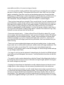
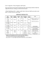
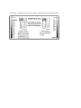
1. Stock Carb Specs (U.S.) - Here's a useful chart to help you identify your carbs, re-jet
them, or choose a set for a carb swap .....
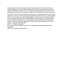
2. Basic CV Carb Operation - Here's a diagram outlining the basic systems and how the CV carb
operates. Open it in a separate window and follow along as you read the text .....
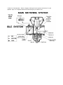
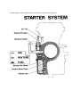
3. Starter System - Here's another outlining the Starter or Choke Circuit operation .....
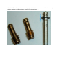
4. Pilot Jets - A comparison chart of the 2 types of pilots used in the stock 650 carbs .....
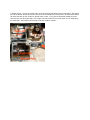
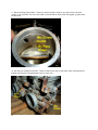
5. Starter Circuit - A photo of a rather ratty set of 34s showing the Starter Circuit components. The Starter
jet is at the bottom of that bored hole in the lip of the float bowl and not removable. All these parts need to
be clean and clear for the "choke" to operate. Also of note - if you get new float bowl gaskets, they will
have 2 punch-outs along the edge. One is right over that bored hole, the other about an inch away along
the same side - both need to be punched out for the choke to operate .....
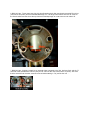
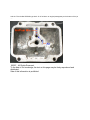
6. BS34 Air Jets - Those same ratty 34s, this time illustrating their often mentioned removable Pilot air jet
(removed in this photo) and the fixed Main/Midrange one. The larger holes above them are air vents for
the float chamber and the slot at the top feeds the slide/diaphragm to create vacuum and make it lift
....
7. BS38 Air Jets - Similarly located but on opposite sides compared to the 34s, both are fixed, and the '77
and older carbs indicated the main air jet by an "M" cast into the carb mouth next to it (arrow). Also note
that the external float chamber vents were moved inside starting in '78, just like the 34s .....
8. "No Hole" Pilot - Compared to a standard pilot jet with bleed holes. Also note the Mikuni needle - clip
positions (notches or slots) are always counted from the top down .....
9. BS38 Mix Screw Location - Also note the vacuum ports available on the 38s (arrows). A suitable
threaded nipple can be installed in place of the block-off screw to enable gauge hook-up for syncing. This
is only necessary if you have no vacuum barbs on your intake manifolds ('77 and older). The size is a
standard M6 x 1.00 .....
10. BS34 Mix Screw Location - Block-off cap and screw removed in this photo .....
11. Mix Screw & By-Pass Outlets - These tiny holes must all be clear for your pilot circuit to function
properly. This is a BS34. The mix screw outlet on the 38s will be offset to the side slightly, by-pass holes
are the same .....
12. Idle and Sync Adjustment Screws - These are 38s but the 34s are the same. Older carb sets with no
linkage would have an idle adjustment screw on each carb .....
©
13. BS38 Float Bowl Variations - There are internal differences in the float bowls that use the VM22/210
pilot jets as opposed to those running the BS30/96 style. This involves the air passage that feeds air to
the jet. This means that the bowl will only work with the type of pilot it was designed for. Here's the
VM22/210 type used from '76 on. Air is directed across the top of the bowl to the top of the jet .....
And the '75 and older BS30/96 type bowl. Air is fed down an angled passageway to the bottom of the jet
.....
©2007, , All Rights Reserved.
To the best of our knowledge, the text on this page may be freely reproduced and
distributed.
Sale of this information is prohibited.