1
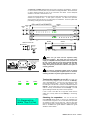
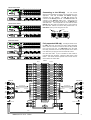
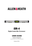
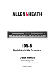
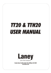
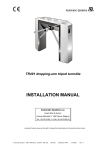
iDR D-in/out DIGITAL EXPANDERS
AP6636
User Guide
lock
link
power
iDR D-in
DIGITAL AUDIO INPUT EXPANDER
lock
link
power
iDR D-out
DIGITAL AUDIO OUTPUT EXPANDER
Laite on liitettävä suojamaadoituskoskettimilla varustettuun pistorasiaan
Apparatet må tilkoples jordet stikkontakt
Apparaten skall anslutas till jordat uttag
ATTENTION: REMPLACER PAR UN FUSIBLE STRICTEMENT IDENTIQUE EN VALEURS.
FOR CONTINUED PROTECTION AGAINST RISK OF FIRE
next
REPLACE FUSE WITH SAME TYPE AND RATING.
4
EXPANDER INPUTS
previous
OUT DR-LINK IN
FUSE: T500mA L
250V 20mm
ALLEN&HEATH
iDR D-in
AUDIO OUT
3
AES IN
S/PDIF IN
2
AES IN
S/PDIF IN
AES IN
S/PDIF IN
1
AES IN
1
AES OUT
S/PDIF IN
CAUTION
RISK OF ELECTRIC SHOCK
DO NOT OPEN
THIS APPARATUS MUST BE EARTHED.
CET APPAREIL DOIT ETRE MIS A LA TERRE
DIGITAL EXPANDER
100 - 240V~
47-63Hz ~ 25W MAX
S/N
AVIS: RISQUE DE CHOC ELECTRIQUE - NE PAS OUVRIR.
Laite on liitettävä suojamaadoituskoskettimilla varustettuun pistorasiaan
Apparatet må tilkoples jordet stikkontakt
Apparaten skall anslutas till jordat uttag
DIGITAL INPUTS
Made in the UK by ALLEN&HEATH LIMITED
ATTENTION: REMPLACER PAR UN FUSIBLE STRICTEMENT IDENTIQUE EN VALEURS.
FOR CONTINUED PROTECTION AGAINST RISK OF FIRE
next
REPLACE FUSE WITH SAME TYPE AND RATING.
4
EXPANDER OUTPUTS
previous
OUT DR-LINK IN
FUSE: T500mA L
250V 20mm
ALLEN&HEATH
iDR D-out
AUDIO IN
S/PDIF OUT
3
AES OUT
2
AES OUT
S/PDIF OUT
S/PDIF OUT
AES OUT
S/PDIF OUT
CAUTION
RISK OF ELECTRIC SHOCK
DO NOT OPEN
THIS APPARATUS MUST BE EARTHED.
CET APPAREIL DOIT ETRE MIS A LA TERRE
DIGITAL EXPANDER
100 - 240V~
47-63Hz ~ 25W MAX
AVIS: RISQUE DE CHOC ELECTRIQUE - NE PAS OUVRIR.
S/N
Made in the UK by ALLEN&HEATH LIMITED
DIGITAL OUTPUTS
iDR D-in and iDR D-out are add-on digital audio expander units for the Allen & Heath iDR-4 and iDR-8 audio mix
processors. They provide AES3 and SPDIF format digital audio inputs and outputs to add to the analogue audio
connections on the main unit. The iDR D-in has 8 inputs arranged as 4 pairs. Either the AES3 (XLR) or the SPDIF
(RCA phono) input may be selected for each pair. The iDR D-out has 8 outputs arranged as 4 pairs. These provide
AES3 and SPDIF outputs simultaneously available. Only one input and one output expander may be added to the iDR
system bringing it up to a maximum 16x16 audio matrix. This may be any combination of the analogue and digital
expanders available for the iDR system. These units do not have any processing built in. They simply convert the
AES3 and SPDIF formats to work with the 8 channel wide iDR digital bus which feeds the main unit via a CAT5 STP
cable. The processing and mixing is handled by the main iDR-4 or iDR-8 unit which features the full 16x16 DSP matrix.
The iDR System Manager software is used to select either the AES3 or the SPDIF connection for each expander input
pair. Both expander units have 8 front panel LEDs in addition to the 3 status indicators. These are 3-colour soft LEDs
which can be assigned as audio meters, mute indicators or patch related indicators. They are programmed in the
usual way using the iDR System Manager software. Control of the expanders is via the DR-Link port using a CAT5 STP
cable. This means that two CAT5 cables are required to interconnect an expander to the main unit. Maximum distance
between the units is 250 metres. Local mains power is required.
This product complies with the European Electromagnetic
Compatibility directives 89/336/EEC & 92/31/EEC and the
European Low Voltage Directives 73/23/EEC & 93/68/EEC.
NOTE: Do not remove the cover of the unit. There are no user serviceable
parts inside. Any changes or modifications to the equipment not approved by
Allen & Heath could void the compliance of the equipment and therefore the
users authority to operate it.
iDR D-in/out User Guide AP6636 Issue 1
Copyright © 2008 Allen & Heath Limited. All rights reserved
Whilst we believe the information in this guide to be reliable we do not assume
responsibility for inaccuracies. We also reserve the right to make changes in
the interest of further product development.
iDR D-in/out User Guide AP6636
1
The iDR D-in and iDR D-out expanders can be rack mounted or free standing. There are
no user controls on the front panel, only the status and assignable LEDs. Allow a minimum
of 75mm clearance behind the unit for the connectors and cables. Ensure adequate
ventilation to the side of and behind the unit.
The units are shipped with their rack ears fitted and feet removed ready to be mounted in a
standard 19” equipment rack. 1U rack space is required. For desk mount operation
remove the two rack ears using a Torx (star head) T10 screwdriver. Fit the four plastic feet
provided by pressing them into the underside.
44mm
48mm 1.7"
1.9" 1U
iDR-in and iDR-out EXPANDERS
443mm
17.4"
lock
link
483mm
19"
power
iDR-in
AUDIO INPUT EXPANDER
lock
link
power
iDR-out
AUDIO OUTPUT EXPANDER
307mm
12"
Remove 2x rack ears
M3 Torx T10
Fit 4x feet
Laite on liitettävä suojamaadoituskoskettimilla varustettuun pistorasiaan
Apparatet må tilkoples jordet stikkontakt
Apparaten skall anslutas till jordat uttag
ATTENTION: REMPLACER PAR UN FU
FOR CONTINUED PROTECTION AGAIN
REPLACE FUSE WITH SAME TYPE AN
FUSE: T500mA L
250V 20mm
CAUTION
RISK OF ELECTRIC SHOCK
DO NOT OPEN
THIS APPARATUS MUST BE EARTHED.
CET APPAREIL DOIT ETRE MIS A LA TERRE
100 - 240V~
47-63Hz ~ 25W MAX
AVIS: RISQUE DE CHOC ELECTRIQUE - NE PAS OUVRIR.
232mm
9.1"
75mm
3"
Make sure you have read the Important Safety
Instructions provided. Also check that your local mains
supply is compatible with that printed on the rear panel of
the unit. Ensure that the correct mains lead with moulded
plug and IEC connector has been supplied. For your own
safety and optimum performance make sure the system is
correctly grounded.
To avoid any unexpected audible clicks or thumps
always turn connected power amplifiers down or off before
switching the iDR or any other signal equipment on or off.
Turning the expander on or off
lock
link
power
First make sure
the unit is correctly plugged up and connected to the iDR-4(8).
This is described below. Turn the unit on by pressing the rear
panel power ON/OFF switch. The power LED lights up. The
link LED lights if the DR-Link connection is established with the
iDR-4(8). The lock LED lights once the link is established and
audio is correctly communicated with the iDR-4(8). The iDR
System Manager detects the presence of the expander.
If one or more of the LEDs do not light then check that the
cables are correctly fitted and the iDR-4(8) is functioning
normally.
*8 Diagnostics
Audio Exp:In/Out
2
Checking for expanders You can use the front
panel iDR-4(8) Setup menus to check if any expanders are
connected and recognised. This is useful when the expanders
are located far away from the main unit. With the face plate
removed access menu *8 Diagnostics and scroll to Audio Exp.
Refer to the iDR-4 user guide AP5230 or iDR-8 user guide
AP4530 for further details.
IDR D-in/out User Guide AP6636
CONNECTING THE INPUT EXPANDER
IN
8
7
6
5
4
3
2
1
OUT 8
7
6
5
4
3
2
1
IN OUT
DR-LINK
AUDIO
iDR
IN
12 LR
11 LR
10 LR
9 LR
iDR D-in
OUT
CONNECTING THE OUTPUT EXPANDER
IN
8
7
6
5
4
3
2
1
OUT 8
7
6
5
4
3
2
1
IN OUT
iDR
Connecting to the iDR-4(8)
You can connect
either or both expanders according to the requirements of your
application. Note that the iDR-in and iDR-out analogue
expanders are also available. The iDR D-in AUDIO OUT
connects to the iDR-4(8) AUDIO IN. The iDR D-out AUDIO IN
connects to the iDR-4(8) AUDIO OUT. Ensure that the
expander DR-Link IN connects to DR-Link on the iDR-4(8) it is
associated with. If both expanders are used with the same
iDR-4(8) then daisy chain from DR-Link OUT of one to DR-Link
IN on the other. DR-Link can also be daisy chained from or to
iDR-switch units if you are using them as well.
next
AUDIO
DR-LINK
previous
OUT DR-LINK
OUT
12 LR
11 LR
10 LR
IN
AUDIO OUT
9 LR
iDR D-out
IN
DIGITAL EXPANDER
CONNECTING BOTH EXPANDERS
IN
8
7
6
5
4
3
2
1
OUT 8
7
6
5
4
3
2
1
Fully expanded iDR-4(8)
IN OUT
AUDIO
DR-LINK
iDR
IN
12 LR
11 LR
10 LR
9 LR
OUT
12 LR
11 LR
10 LR
9 LR
iDR D-in
The diagram below shows
the iDR-8 with both the input and output digital expanders
fitted. Note the connection of DR-Link which is daisy chained
from one unit to the next. If an iDR-switch unit is also fitted
then daisy chain DR-Link from the last expander to the switch
unit. Make sure you plug into the correct DR-Link socket.
DR-LINK
AUDIO
OUT
iDR D-out
IN
INPUT
iDR D-in
AES
Use CAT5 STP cable. A pair of standard 2 metre cables is
provided with each expander. Maximum cable length is 250
metres. This means that the expander units can be used for
remote audio over CAT5 cable.
iDR-8
OUTPUT
1
1
2
2
3
3
4
4
5
5
6
6
7
7
8
8
9
9
iDR D-out
AES
SPDIF
SPDIF
Select
250 metre max
AES
SPDIF
AUDIO IN
AUDIO OUT
Select
CAT5
AES
10
10
11
11
12
12
13
13
250 metre max
AES
AUDIO OUT
SPDIF
AUDIO IN
CAT5
AES
SPDIF
SPDIF
Select
AES
14
14
15
15
AES
SPDIF
SPDIF
16
16
Select
SIG GEN
OUT IN
DR-Link
DR-Link OUT IN
ACTIVE MONITOR
DR-Link
CAT5
CAT5
iDR D-in/out User Guide AP6636
3
AUDIO
DR-LINK
iDR D-in
OUT IN
IN
12 LR
11 LR
10 LR
9 LR
OUT
Expanded multiple iDR system
IN
8
7
6
5
4
3
2
1
OUT 8
7
6
5
4
3
2
1
8
7
6
5
4
3
2
1
OUT 8
7
6
5
4
3
2
1
OUT
DR-LINK IN
AUDIO
iDR
IN
DR-LINK
iDR
OUT
This diagram
shows an iDR system with two iDR-8 units and both expanders
fitted. A system could also be created with iDR-4 units or a mix
of iDR4 and iDR-8 units. Note that the digital or analogue
expanders may be used, but only one input and one output
expander may be added per system. DR-Link is only required
to connect to the expanders, not between the main units.
Make sure you connect DR-Link to the iDR associated with
each expander. Make sure you plug into the correct DR-Link
socket. In this case do not daisy chain DR-Link from one
expander to the other.
IN
OUT
12 LR
11 LR
10 LR
9 LR
iDR D-out
IN
DR-LINK
OUT IN
Use CAT5 STP cable. Maximum cable length is 250 metres.
Maximum audio matrix is 16x16. The audio link cable carries 8
channels. This can provide a distributed system with 8
common channels and 8 local channels at each unit.
Working with iDR System Manager The online
Editor recognises any expanders connected. If you are
working offline then a simulation of the expanders is provided.
This is the same for either the analogue or digital output
expander. If you want to simulate a digital input expander then
select this from the File / Preferences / Expander Options
menu. When choosing a digital input as a channel Source you
can select either the AES3 or the SPDIF connection. The
digital input selection is also available as a parameter which
can be stored and recalled in the presets.
For further information refer to the Allen & Heath web site or
contact Technical Support in your area.
www.allen-heath.com
Inputs x8
Soft LEDs
4x pairs AES3 and SPDIF
Assignable by the installer
Sample rate conversion
iDR D-in 8x front panel indicators
Select using iDR System Manager
iDR D-out 8x front panel indicators
Outputs x8
Function 3-colour signal meters
4 pairs AES3 and SPDIF
Mute on/off (red)
Both formats available simultaneously
Static patch related (one of 3 colours)
Expander Input / Output Port
Power Supply
Proprietary 8 channel digital audio
Universal mains input switched mode design
Connects to iDR-4 or iDR-8 main unit
IEC 3pin socket
CAT5 STP cable up to 250 metres (825 feet)
Country dependent mains lead supplied
DR-Link Port
Serial control of iDR expander units
Proprietary Allen & Heath control protocol
IN and OUT ports provided to allow daisy
chaining through multiple units
CAT5 STP cable up to 250 metres (825 feet)
Status LEDs
Power –mains power on
Link – DR-Link control communication
Lock –audio communication
4
3-colour – green, yellow, red, off
Rear panel power on/off switch
AC mains input 100-240V AC 50/60Hz
25VA max
Fuse T500mAL 20mm
Mechanical
1U rack
483 x 232 x 44mm
19” x 9.1” x 1.7”
Desk
443 x 232 x 48mm
Weight
3.5kg, 7.7lbs
17.4” x 9.1” 1.9”
IDR D-in/out User Guide AP6636