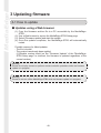
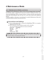
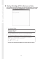
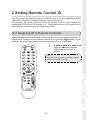
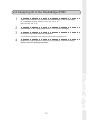
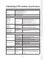
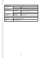
1
MediaEdge-STB3
Setup Guide
MediaEdge-STB3
Setup Guide
November 30, 2006
Copyright © 2006 Canopus Co., Ltd.
All rights reserved.
Engineered by Canopus Co., Ltd.
Copyright Regulations
It is illegal for anyone to violate any of the rights provided by the copyright laws to the owner of copyright,
except for fair use (mainly private noncommercial use). Also, in certain cases copying is prohibited with no
exceptions. In no event shall Canopus be liable for any direct or indirect damages whatsoever arising from
the use of captured materials.
Warranty
Your MediaEdge-STB3 options are covered by a limited warranty when you register your Canopus product.
This warranty is for a period of three years from the date of purchase from Canopus or an authorized
Canopus agent. This warranty applies only to the original purchaser of the Canopus product and is not
transferable. Canopus Co., Ltd warrants that for this period the product will be in good working order.
Should our product fail to be in good working order, Canopus will, at its option, repair or replace it at no
additional charge, provided that the product has not been subjected to misuse, abuse or non-Canopus
authorized alterations, modifications and/or repair. Proof of purchase is required to validate your warranty.
Canopus is not responsible for any lost profits, lost savings or other incidental or consequential damages
arising out of the use of, or inability to use, this product. This includes damage to property and, to the extent
permitted by law, damages for personal injury. This warranty is in lieu of all other warranties of
merchantability and fitness for a particular purpose.
Cautions
Please observe the following cautions when using this product. If you have any questions regarding the
method of usage, the descriptions herein, or any other concerns, please contact the local Canopus office or
distributor.
WARNING
The following conditions indicate the potential for serious bodily injury or loss of life.
Health precautions
In rare cases, flashing lights or stimulation from the bright light of a monitor display may trigger temporary
epileptic seizures or loss of consciousness. It is believed that even individuals whom have never
experienced such symptoms may be susceptible. If you or close relatives have experienced any of these
symptoms, consult a doctor before using this product.
Do not use in environments requiring a high degree of reliability and safety
This product is not to be used in medical devices or life support systems. The characteristics of this product
are not suited for use with such systems.
Protect against static electricity
An electrostatic discharge may damage components of this product. Do not directly touch any of the
connectors or component surfaces.
Static electricity can be generated on clothing and on people. Before handling the product, discharge static
electricity from your body by touching a grounded metal surface.
Do not disassemble
Do not remove the cover or modify the MediaEdge-STB3. Fire, electric shock or malfunction may result. For
internal inspection or repair, please contact your system integrator or Canopus directly.
Do not operate at other than the specified voltage
Do not operate at other than the specified voltages of AC 100-240V. Operation at other than the rated
voltage may result in fire or malfunction.
Do not operate with other than the specified power supply
Do not operate with other than the specified AC adapter, or with a car power supply. Such operation may
result in fire or malfunction.
Handle the AC adapter cord carefully
Do not place heavy objects on top of the cord, or place it near hot objects. Doing so may damage the cord
and result in fire, electrical shock, or malfunction. Altering the cord, or excessively bending or pulling the
cord may result in fire or electrical shock. If the cord is damaged, please contact your local retail outlet or
Canopus directly.
* Replacement of damaged parts, unless defective due to manufacturing, will be charged at actual cost plus
handling fees.
Do not use the product in a dusty or humid environment
It may cause a short-circuit or a build-up of heat, resulting in fire or electric shock.
Do not let foreign matters enter the inside of the product
If water or any foreign matter enters the inside of the product, it may cause fire or electric shock. In the case
where water or foreign matter is allowed to enter the product, turn the power OFF and pull out the power
cable from the receptacle.
Do not use the product when you hear thunder
Do not touch the product body or its plug on such occasions. It may result in electric shock.
Stop using the product when it is smoking
Do not use the product in an abnormal condition like when it is smoking or emitting an odor.
It may result in fire or malfunction of the product. If any anomaly is found, turn OFF the power of the
product, disconnect the power cable, making sure that the product is not smoking any more.
Do not use the product in a damaged condition
Do not drop the product nor use the product with its cover broken.
It may result in fire or malfunction of the product. In case the product is damaged, turn OFF the power of the
product and pull out the power cable from the receptacle.
Do not touch AC adapter with wet hands
Do not disconnect or plug in the AC adapter when your hands are wet. Contact with water may result in
electric shock, fire or damage.
Do not setup in an area that becomes hot
Do not setup in an area exposed to direct sunlight or near a heating apparatus. The heat can accumulate,
causing burns, fire or damage. Also, the unit may become deformed or change color.
CAUTION
The following conditions indicate the potential for bodily harm, damage to hardware or loss of data.
Do not pull AC adapter cord when disconnecting from electrical outlet
When disconnecting the AC adapter cord, pull on the plug, not the cord itself. Pulling on the cord can
damage the cord and may result in fire or electric shock.
Do not setup other than the Described method
Do not setup in a manner other than prescribed. Do not use while wrapped in cloth or plastic. Heat can
accumulate, causing burns, fire or damage.
If product will not be used for an extended period
If this product will not to be used for an extended period of time, disconnect the AC adapter from the
electrical outlet.
Do not place the product on an unstable place
Do not place the product on an unstable table or slanted surface. The product may fall from it, resulting in
injuries or malfunction of the product.
Turn OFF the power when cleaning the product
When making connections with the product or cleaning the product, be sure to disconnect the power plug
beforehand. Failure to do so may result in electric shock or malfunction of the product. When cleaning the
product, do not use volatile solvents such as thinner.
Route the cables properly
Route the power cable and AV cables properly. If they catch on something, it may result in injuries or
malfunction of the product.
Precautions for use of AC adapter
The supplied AC adapter and power cord are for exclusive use of this product. Do not operate the product
with other AC adapter or in other combinations.
Lower The Volume Of The Audio Equipment
Please lower your audio equipment speaker level that is connected with the MediaEdge-STB3 when you
turn the power of the MediaEdge-STB3 ON/OFF. You may hear a loud noise when you turn the power ON/
OFF.
Do not cover the MediaEdge-STB3 ventilation
Do not use the MediaEdge-STB3 covered with a cloth or in an ill-ventilated room.
Covering the vent may cause heat inside of the product resulting in fire or product malfunction.
FCC Notice
This equipment has been tested and found to comply with the limits for a Class A digital device, pursuant to
Part 15 of the FCC Rules. These limits are designed to provide reasonable protection against harmful
interference when the equipment is operated in a commercial environment. This equipment generates,
uses, and can radiate radio frequency energy and, if not installed and used in accordance with the
instruction manual, may cause harmful interference to radio communications.
Operation of this equipment in a residential area is likely to cause harmful interference in which case the
user will be required to correct the interference at his own expense.
CE Notice
WARNING
This is a Class A product. In a domestic environment this product may cause radio interference in which
case the user may be required to take adequate measures.
Declaration of Conformity
According to FCC Part 15
Responsible Party Name:
Canopus Corporation
Address:
711 Charcot Avenue, San Jose, CA 95131
Telephone:
408-954-4500
Declares that product Model: ME-STB3(A)
Complies with Part 15 of the FCC Rules.
Product Notes
1. Unauthorized copying of a portion or the entirety of this product is prohibited.
2. The description and specifications of this product are subject to future change without notice.
3. The description of this product has been prepared to be as complete as possible. If the reader is aware
of any questionable points, errors or omissions, please contact Canopus.
4. The company assumes no liability for the results of practical application, regardless of item (3) above.
5. Regardless of whether negligence occurs during usage, the company assumes no liability, even if there
is a claim, for extraordinary, incidental or derivative loss, including the loss of profits, that arise during
practical application of this product.
6. The analysis, reverse engineering, decompiling and disassembling of the software, hardware or
manuals that accompany this product, and all other related products including miscellaneous
supplemental items, are prohibited.
7. Canopus, as written in both English and Japanese, and its logo are registered trademarks of Canopus
Co., Ltd.
8. MediaEdge is a trademark of Canopus Co., Ltd. Other product names and the like are trademarks or
registered trademarks of the respective companies.
About the Documentation
This document is the MediaEdge-STB3 Setup Guide.
Information not listed in this document may be listed elsewhere.
In cases where there is a difference between a description in this document and an actual operation
method, the actual operation method takes precedence.
This document is written for users capable of performing basic PC operations. If there is no special
description of an operation, perform that operation in the same manner as a general PC operation.
To simplify the descriptions, the actual product may differ from the illustrations and screenshots.
Table of Contents
Chapter 1 - Before Installation
1 Introduction.................................................................................... 2
1-1 Notes regarding usage .............................................................................2
1-2 Verify package contents ...........................................................................2
1-3 Canopus website ......................................................................................3
1-4 GNU General Public License ...................................................................3
2 MediaEdge-STB3 .......................................................................... 4
2-1 Overview ..................................................................................................4
2-2 Features ...................................................................................................5
2-3 Users and Administrators .........................................................................5
2-4 Operation mode of MediaEdge-STB3 ......................................................6
2-5 Setting Up MediaEdge-STB3 ...................................................................6
3 MediaEdge-STB3 Parts Names .................................................... 7
3-1 Front Panel ...............................................................................................7
3-2 Rear Panel ...............................................................................................8
3-3 Remote Controller ....................................................................................9
Chapter 2 - Connecting MediaEdge-STB3
1 Connecting to the MediaEdge-SVS3 Server ................................ 12
1-1 Connecting MediaEdge-STB3 .................................................................13
1-2 MediaEdge-STB3 setting using DHCP....................................................14
1-3 MediaEdge-STB3 setting without using DHCP .......................................17
1-4 Verify MediaEdge-STB3 operations ........................................................21
2 Connecting to the MediaEdge-LEB/LEB60 .................................. 23
2-1 Connect MediaEdge-STB3 .....................................................................23
2-2 Setting IP address of MediaEdge-STB3 and URL for menu page ..........24
2-3 Verify MediaEdge-STB3 operations ........................................................27
Chapter 3 - Setting Up MediaEdge-STB3
1 Setup using Web browser ............................................................ 30
1-1 Accessing the MediaEdge-STB3 Setup page .........................................30
1-2 MediaEdge-STB3 Setup Page ................................................................30
2 Setup using DIP switches ............................................................. 44
2-1 WOL(Wake On LAN) ...............................................................................44
2-2 Setting Video Output Format ...................................................................44
3 Updating firmware ........................................................................ 46
3-1 How to update .........................................................................................46
4 Maintenance Mode ....................................................................... 47
4-1 Maintenance Mode overview ..................................................................47
4-2 Firmware recovery...................................................................................49
4-3 If you have forgotten the user name or the password .............................51
Chapter 4 - APPENDIX
1 Limitations .................................................................................... 54
2 Setting Remote Control ID ........................................................... 55
2-1 Assigning ID to Remote Controller ..........................................................55
2-2 Assigning ID to the MediaEdge-STB3 .....................................................57
3 FEC (Forward Error Correction) Functions .................................. 58
4 MediaEdge-STB3 Hardware Specifications ................................. 59
MediaEdge
Chapter 1 - Before Installation
1
- Introduction
- MediaEdge-STB3
- MediaEdge-STB3 Parts Names
-1-
MediaEdge
1 Introduction
1-1 Notes regarding usage
IN NO EVENT SHALL CANOPUS BE LIABLE TO USER OR ANY OTHER PARTY
FOR INCIDENTIAL, CONSEQUENTIAL OR SPECIAL DAMAGES ARISING UNDER
THE USE OF THIS PRODUCT WHETHER UNDER THEORY OF CONTRACT,
TORT, INDEMNITY, PRODUCT LIABILITY OR OTHERWISE.
EXCEPT AS OTHERWISE EXPRESSLY PROVIDED HEREIN, CANOPUS MAKES
NO REPRESENTATIONS, EXTENDS NO WARRANTIES OF ANY KIND, EXPRESS
OR IMPLIED, INCLUDING THE WARRANTIES OF MARCHANTABILITY,
NON-INFRINGEMENT OR FITNESS FOR A PARTICULAR PURPOSE, AND
ASSUMES NO RESPONSIBILITY WITH RESPECT TO THE USE OF THIS
PRODUCT HEREUNDER. FURTHER, CANOPUS MAKES NO WARRANTIES OF
P R O P E R O P E R AT I O N O F T H I S P R O D U C T U N D E R O T H E R U S A G E
ENVIRONMENT THAN THAT RECOMMENDED BY CANOPUS FOR THIS
PRODUCT.
Unauthorized recording of copyrighted television programmes, compact discs,
digital versatile discs, video tapes and other materials may infringe the right of
copyright owners and be contrary to copyrights laws.
1-2 Verify package contents
Please verify that the following accompanying components are included in the
MediaEdge-STB3 package.
❑ MediaEdge-STB3 Unit
❑ AC adapter & cable
❑ BNC-RCA conversion connector (x3)
❑ Remote Controller
❑ AAA battery (x2)
❑ Manuals
-2-
1-3 Canopus website
Including MediaEdge, the latest company information is announced at our website
http://www.canopus.com. The latest drivers, utilities, product manuals, FAQs, etc.
are also available, from our website.
1-4 GNU General Public License
This product utilizes the free software that uses GNU General Public License
(hereinafter “GPL”) or GNU Lesser General Public License (hereinafter “LGPL”) in a
part of the software.
MediaEdge
-3-
MediaEdge
2 MediaEdge-STB3
2-1 Overview
MediaEdge is an IP-based video distribution/playing system that consists of a
server that stores and distributes MPEG video and terminals, which receive/play
video streams. MediaEdge-STB3 is a set-top box that converts the distributed
MPEG stream into video signal so as to display on TV monitors.
MediaEdge Server
Switching HUB
MediaEdge-STB3
TV monitor
MediaEdge-STB3
TV monitor
MediaEdge-STB3
TV monitor
-4-
2-2 Features
● Supports MPEG-1/2 video SD/HD.
● Supports MPEG-1 Layer-2 audio.
● Provides two VOD modes (Menu mode using VOD menu and
Channel mode without menus).
● Equipped with W3C-compliant browser.
● VOD menus support forms and cookies. User authentication and
user-specific menus can be provided.
● Pause and Jump functions are available for content being watched.
● Internet Explorer 6 (hereafter, web browser) can be used to change
settings for and remotely operate MediaEdge-STB3.
● Allows basic setup and repair of the system using a serial port
(Maintenance Mode).
● Provides a firmware update function that works over the network.
● Provides a remote serial port function.
● Supports HD signal: 1080i, 720p. Supports SD signal: NTSC/PAL
format.
● Supports Component, DVI-D output.
● FEC (Forward Error Correction) function can correct errors on
streaming data.
● Users
Users are those who operate MediaEdge-STB3 to view video content.
● Administrators
Administrators are those who set the operating mode and operating
parameters of MediaEdge-STB3.
Info:
This manual is written for STB3 administrators. For user operations and other such
information, see the “MediaEdge-STB3 Operation Guide” that came with the product.
-5-
MediaEdge
2-3 Users and Administrators
MediaEdge
2-4 Operation mode of MediaEdge-STB3
■ Operating Modes
Menu Mode
In this mode, users select and play desired content from a menu screen. The
menu is acquired from the Web server.
The menu screen reappears after content is finished playing.
Channel Mode
Instead of using the menu screen, this mode allows for the selection of content
using numeric buttons on the remote controller, much like changing channels on
a TV. Channel numbers 1 through 99 are available. When no content (channel) is
selected, or when the selected content is finished playing, video defined as the
Default Content will automatically start playing. In the Channel mode, the
relations between the channel numbers and the contents (RTSP URL) must be
specified in advance.
* The operating mode must be set, in advance, by an administrator. It cannot be switched while users
are operating MediaEdge-STB3.
* The operating mode is set to Menu Mode at the time of factory shipment.
■ Maintenance Mode
Holding the reset switch down for several seconds starts Maintenance Mode. In
this mode, nothing is displayed on the screen. Use a terminal program on a
computer connected to MediaEdge-STB3 via a serial cable to perform
maintenance operations. Via the serial port, you can update firmware or execute
other operations.
2-5 Setting Up MediaEdge-STB3
Following are the directions to set up MediaEdge-STB3.
Individual client setting using a Web browser.
Use a Web browser to access the MediaEdge-STB3 you want to set up, open the
Settings page, and then configure the settings you want. You can configure
different settings on each client. You can also initialize the settings, reboot
MediaEdge-STB3, and update its firmware.
* The setting using a Web console can be performed only by Internet Explorer 6.
-6-
3 MediaEdge-STB3 Parts Names
3-1 Front Panel
(1)
(2)
(3)
(4)
(5)
(6)
(7)
-7-
MediaEdge
(1) POWER LED
Lights while MediaEdge-STB3 operates.
Unlit:
Power is not on.
Lit orange:
Stand-by.
Flashing orange: Wake On LAN Stand-by.
Lit green:
Operating.
Flashing green: Starting up/shutting down.
(2) LINK LED
Lights when MediaEdge-STB3 is connected to a network (via a hub or other
such device).
(3) TX LED
Lights when MediaEdge-STB3 is sending data to the network.
(4) RX LED
Lights when MediaEdge-STB3 is receiving data from the network.
(5) COM LED
Lights when MediaEdge-STB3 is sending/receiving data via COM port.
(6) KEY LED
Lights when receiving a key signal from an infrared remote controller or an
external remote terminal.
(7) Infrared receiver
Built in infrared receiver for remote controllers.
MediaEdge
3-2 Rear Panel
(2) (4)
(1)
(1)
(2)
(3)
(4)
(5)
(6)
(7)
(8)
(9)
(10)
(11)
(12)
(13)
(3) (5)
(8)
(6)
(7)
(10)
(11)
(12)(13)
(9)
DVI-D
DVI-D signal output.
AUDIO OUT-LEFT
Audio output (left).
AUDIO OUT-RIGHT
Audio output (right).
S/PDIF
Coaxial digital audio output.
VIDEO OUT
Composite video signal output.
S VIDEO OUT
S-video signal output.
COMPONENT VIDEO OUT
Component video (Y/Pb/Pr) output.
LAN
Port for connecting to Ethernet.
REMOTE
Remote terminal.
DIP switches
Used to enable WOL (Wake On LAN), or change the video output format (Refer
to Chapter 3 for details).
COM
RS-232C (for pass-through) terminal.
RESET
Used in emergencies. Do not use to reset.
Power terminal
Connects to the accompanying AC adapter. Never connect anything here
other than the accompanying AC adapter.
-8-
3-3 Remote Controller
(1)
(1) POWER button
Turns power on/off.
(2) MENU button
Displays the "home menu" screen.
(3) Numeric buttons
Use to access content and enter numbers.
(4) Navigation buttons
Use to play content and select menus.
(5) Function button
Displays the system information. Only the
button is used.
(6) Play mode button
Not used.
(7) Display button
Use to show/hide the OSD during playback.
(8) Volume button
Use to adjust volume.
(2)
(3)
(4)
(5)
(6)
(7)
(8)
-9-
MediaEdge
Info:
The functions available for a remote controller differ in accordance with administrator
settings.
-10-
MediaEdge
MediaEdge
Chapter 2 - Connecting MediaEdge-STB3
2
This chapter describes the procedures to connect
your MediaEdge-STB3 to a stream server (Server
PC where Media-Edge-SVS3 has been installed
or MediaEdge-LEB/LEB60) to play back content.
- Connecting to the MediaEdge-SVS3 Server
- Connecting to the MediaEdge-LEB/LEB60
-11-
MediaEdge
1 Connecting to the MediaEdge-SVS3 Server
In this manual, the setting procedures are explained using the examples under the
system where the MediaEdge server is configured as follows. See the MediaEdgeSVS3 manual for how to configure the server.
● MediaEdge server function
Web server for server console
Web server for client content
DNS server
DHCP server
(Windows Standard IIS)
(Windows Standard IIS)
(Windows Standard)
(Windows Standard)
● MediaEdge server network settings
IP address
192.168.0.2
Computer name
MEDIAEDGE-SVR
Host name
MEDIAEDGE-SVR
Domain name
localdomain
DNS address
192.168.0.2
DHCP scope
192.168.0.16 - 192.168.0.250/255.255.255.0
* If you use the MediaEdge exclusively on a network system, you can use
these settings as is. Or, you can change some of the settings if necessary.
If changing settings, consult with the operator or the network administrator
who integrates the system.
-12-
1-1 Connecting MediaEdge-STB3
Connect MediaEdge-STB3 to the server computer, referring to the diagram below.
Keep the following verification steps in mind.
MediaEdge-SVS2/SVS3 Server
AC adapter
(Included in the package)
TV Moniter
MediaEdge-STB3
Switching HUB
Conversion connector
Ethernet cable
Ethernet cable
D - Component Conversion Adapter
Audio cable
● Verify Ethernet connection.
Verify that server PC, switching HUB, and MediaEdge-STB3 are connected.
They need to be connected by Ethernet cables.
● Verify connection to TV monitor.
Check that MediaEdge-STB3 and TV monitor are connected properly.
Check that MediaEdge-STB3 VIDEO OUT and AUDIO OUT are connected
to VIDEO IN and AUDIO IN of TV monitor properly.
At the default setting, the video output mode is set to output 1080i (59.
94Hz) signal from the Component (Y/Pb/Pr) output terminals. Configure the
signal settings according to the monitor to be used.
Check that the attached AC adaptor for STB3 is firmly connected to the
MediaEdge-STB3 power terminal.
● Verify dongle connection.
Check that the dongle that came with the MediaEdge-SVS3 is connected to
the USB port of the server computer. Confirm that the red LED is lit in the
dongle. If not, check whether the USB port of your computer is enabled.
● Verify stream server startup.
Select [Start] > [All programs] > [MEDIAEDGE] > [Server Configuration
Tool] to run "Server Configuration" tool. Make sure that Service status is
"running" on the [Service control] tab.
● Install batteries in the remote controller
Install two AAA batteries in the remote controller.
-13-
MediaEdge
● Verify STB3 AC adaptor connection.
MediaEdge
1-2 MediaEdge-STB3 setting using DHCP
MediaEdge-STB3 is configured to use DHCP at the factory setting. In the example
of the MediaEdge network connection shown at the start of this chapter, the
following menu screen will appear on the TV monitor several seconds after the
MediaEdge-STB3 is turned on.
If the menu screen does not appear, follow the steps below to configure the setting.
1. Check that the LINK LED on the front of MediaEdge-STB3 is lit. If it is not lit,
check if the switching Hub is powered and if the Ethernet cables are properly
connected.
2. Check that the DHCP server on the server computer is running and then,
recheck its settings. MediaEdge-STB3 does not display anything until the IP
address is obtained from the DHCP server.
See the installation chapter in the MediaEdge-SVS3 manual for the setting of the
DHCP server.
If the image is distorted, or if it is not synchronized properly, check the following
points.
- Refer to Chapter 3, Section 2 "Setup using DIP switches" and configure the video
output settings of the MediaEdge-STB3 to apply to the monitor.
- The data transmission may not have performed properly, making the data flawed.
Make sure that the network devices (including network cables) are properly
connected and running.
-14-
■ If the menu screen does not appear:
1
2
Press the
button on the remote
controller to display the system
information of the MediaEdgeSTB3.
Check the IP address allocated to
the MediaEdge-STB3.
Ex): IP address: 192. 168. 0. 16
3
On the server computer, run a Web browser and open the MediaEdgeSTB3 Setup page. Enter the IP address of the MediaEdge-STB3 in
[Address].
Ex): http://192. 168. 0. 16/
4
Click [Local settings] to open the
parameter configuration screen.
5
Select [Obtain an IP address
automatically(DHCP)] and [Obtain
DNS server address automatically]
in [Network]. Also, enter the URL
for the menu page in the [Home
URL] field in [Video-on-demand].
* [http://MEDIAEDGE-SVR/sample/stb3/
index. asp] is set as the default URL.
If you have changed the server name,
change [MEDIAEDGE-SVR] to the proper
one.
-15-
MediaEdge
* To modify the Local settings, [User name]
and [Password] are required.
* At the default setting, [admin] is set as the
[User name] with no password set.
MediaEdge
6
If you have changed the local settings, enter [User name] and
[Password] and then click [Save]. After changing the settings, make
sure that the menu screen is properly displayed.
* Clicking the link that says [Save button] will jump to the [Save] button at the bottom of the
Local settings page.
-16-
1-3 MediaEdge-STB3 setting without using DHCP
■ Setting MediaEdge-STB3 IP Address
1
Plug the power cord into an outlet,
press the RESET button on the
rear panel, and then keep holding
the button on the remote
controller.
[MediaEdge-STB3 Network settings] will
start.
-17-
MediaEdge
Note:
If the startup screen does not appear, unplug the MediaEdge-STB3’s power plug, wait at
least 5 seconds, and then perform step 1 again.
•If nothing appears, follow these verification steps:
1.Check that the POWER LED on the front of the MediaEdge-STB3 is lit. If it is not lit,
check the AC adapter and AC power cord connections.
2.Refer to Chapter 3, Section 2 "Setup using DIP switches" and configure the video
output settings of the MediaEdge-STB3 to apply to the monitor.
3.Check the video cable connections on the back of the MediaEdge-STB3 and the TV
monitor. Also, check whether the TV monitor input is switched to the input jack to which
the video cable is connected.
•If [MediaEdge-STB3 Network settings] screen does not appear, with the startup
screen displayed, follow these directions:
1.Make sure to firmly press and continue holding down the
button on the remote
controller. (When the MediaEdge-STB3 receives the signal from the remote controller,
the KEY LED is lit).
2.If the KEY LED does not respond, check if the remote controller ID is properly set, and
if the remote controller’s batteries are properly installed.
MediaEdge
2
3
Use the remote controller and
check [Use the following IP
address].
Specify the IP address with the
remote controller.
Press the
buttons to move the cursor. Enter
the appropriate value by pressing
the [0] to[9] buttons.
In this example, the following values are
entered.
IP address
192.168.0.16
Subnet mask
255.255.255.0
Default gateway 0.0.0.0
* To delete the value at the cursor position,
press the
button.
4
5
Use the remote controller and
check [Use the following DNS
server address].
Specify the IP address with the
remote controller.
Press the
buttons to move the cursor. Enter
the appropriate value by pressing
the [0] to[9] buttons.
In this example, the following values are
entered.
Preferred DNS server 192.168.0.2
Alternate DNS server 0.0.0.0
* To delete the value at the cursor position,
press the
button.
-18-
6
Place the cursor on the [Set]
button and press the button on
the remote controller.
MediaEdge-STB3 will restart, and the
screen shown below will appear.
●If the menu screen does not appear after the MediaEdge-STB3
restarts:
The IP address has not been set. Unplug the MediaEdge-STB3's power
plug, wait at least 5 seconds, and then perform steps 1 to 6 again.
MediaEdge
-19-
MediaEdge
■ If the menu screen does not appear:
1
2
On the server computer, run a Web browser and open the MediaEdgeSTB3 Setup page. Enter the IP address of the MediaEdge-STB3 in
[Address]. (Ex: http://192. 168. 0. 16/)
Click [Local settings] to open the
parameter configuration screen.
* To modify the Local settings, [User name]
and [Password] are required.
* At the default setting, [admin] is set as the
[user name] with no password set.
3
4
Make sure that [Use the following IP address] is selected in [Network],
and that proper values are displayed in [IP address], [Subnet mask],
and [Default gateway] areas.
Then select [Use the following DNS server address], enter the IP
address of the MediaEdge server (Ex: 192. 168. 0. 2) in the [Preferred
DNS server] area, keep the [Alternate DNS server] area [0.0.0.0], and
set [localdomain] to [DNS Domain name].
Also, enter the URL for the menu page in the [Home URL] field in
[Video-on-demand]. [http://MEDIAEDGE-SVR/sample/stb3/index. asp]
is set as the default URL.
If you have changed the local settings, enter [User name] and
[Password] and then click [Save]. After changing the settings, make
sure that the menu screen is properly displayed.
* Clicking the link that says [Save Button] will jump to the [Save] button at the bottom of the
Local settings page.
-20-
1-4 Verify MediaEdge-STB3 operations
■ Verify that the menu screen appears
The following menu screen will appear a few seconds after the startup.
● If nothing appears, follow these verification steps:
1. Check that the POWER LED on the front of the MediaEdge-STB3 is lit. If
it is not lit, check the AC adapter and AC power cord connections.
2. Check the video cable connections on the back of the MediaEdge-STB3
and the TV monitor. Also, check whether the TV monitor input is switched
to the input jack to which the video cable is connected.
■ Verify that sample content can be played
-21-
MediaEdge
Place the cursor on [Database-referencing dynamic menu] and then press the
button. Next, place the cursor on [Sample Contents (HD)] and press the
button. Pressing the button with the cursor on specific content will play it.
MediaEdge
● If video does not appear:
When [Connecting to server. . . ] dialog box does not disappear,
communication with the stream server has failed. Check the installation
procedure and settings thus far. Pay particular attention to the following.
1. Use the [Server configuration tool] and check that the stream server
service (MeSrv) is running.
2. Check that the dongle is attached to a USB port of the server computer
and that the dongle's LED is lit.
-22-
2 Connecting to the MediaEdge-LEB/LEB60
This section explains how to connect a Canopus live encoder box "MediaEdgeLEB" or a MediaEdge-LEB60 (calls "LEB" hereafter), and receive the live stream
sent from the LEB by a MediaEdge-STB3. For LEB setup, see the manuals that
came with the LEB.
2-1 Connect MediaEdge-STB3
Connect MediaEdge-STB3, LEB, and the computer for setup, referring to the
diagram below.
PC for setup
IP address: 192. 168. 0. 2
AC adapter
(Included in the package)
TV Moniter
MediaEdge-STB3
Switching Hub
Conversion connector
Ethernet cable
Ethernet cable
D - Component Conversion Adapter
Audio cable
Video camera
MediaEdge - LEB
IP address: 192. 168. 0. 17
AV cable
- The computer for setup is used to configure the operation parameters of the
MediaEdge-STB3 utilizing a Web browser.
-23-
MediaEdge
Ethernet cable
MediaEdge
2-2 Setting IP address of MediaEdge-STB3 and URL for menu page
■ Setting MediaEdge-STB3 IP Address
1
Plug the power cord into an outlet,
press the RESET button on the
rear panel, and then keep holding
the button on the remote
controller.
[MediaEdge-STB3 Network settings] will
open.
Note:
If the startup screen does not appear, unplug the MediaEdge-STB3’s power plug, wait at
least 5 seconds, and then perform step 1 again.
•If nothing appears, follow these verification steps:
1.Check that the POWER LED on the front of the MediaEdge-STB3 is lit. If it is not lit,
check the AC adapter and AC power cord connections.
2.Refer to Chapter 3, Section 2 "Setup using DIP switches" and configure the video
output settings of the MediaEdge-STB3 to apply to the monitor.
3.Check the video cable connections on the back of the MediaEdge-STB3 and the TV
monitor. Also, check whether the TV monitor input is switched to the input jack to which
the video cable is connected.
•If the [MediaEdge-STB3 Network settings] screen does not appear, with the
startup screen displayed:
1.Make sure to firmly press and continue holding down the
button on the remote
controller. (When the MediaEdge-STB3 receives the signal from the remote controller,
the KEY LED is lit).
2.If the KEY LED does not respond, check if the remote controller ID is properly set, and
if the remote controller’s batteries are properly installed.
-24-
2
3
Use the remote controller and
check [Use the following IP
address].
Specify the IP address with the
remote controller.
Press the
buttons to move the cursor. Enter
the appropriate value by pressing
the [0] to[9] buttons.
In this example, the following values are
entered.
IP address
192.168.0.16
Subnet mask
255.255.255.0
Default gateway 0.0.0.0
* To delete the value at the cursor position,
press the
button.
4
Use the remote controller and
check [Use the following DNS
server address].
* Keep the [Preferred DNS server] and
[Alternate DNS server] at the default value
(0. 0. 0. 0).
Place the cursor on the [Set] button and press the
remote controller.
MediaEdge-STB3 will restart.
-25-
button on the
MediaEdge
5
MediaEdge
■ Setting menu page URL to MediaEdge-STB3
1
2
Using the computer for setup, run a Web browser and open the
MediaEdge-STB3 Setup page. Enter the IP address of the MediaEdgeSTB3 in [Address]. (Ex: http://192. 168. 0. 16/)
Click [Local settings] to open the
parameter configuration screen.
* To modify the Local settings, [User name]
and [Password] are required.
* At the default setting, [admin] is set as the
[User name] with no password set.
3
4
Make sure that [Use the following IP address] is selected in [Network],
and that proper values are displayed in [IP address], [Subnet mask],
and [Default gateway] areas.
Then select [Use the following DNS server address], enter [0. 0. 0. 0]
in the [Preferred DNS server] and [Alternate DNS server] areas, and
set [localdomain] to [DNS domain name].
Also, enter the URL for the menu page [http://(IP address of LEB)/
menu/] in the [Home URL] field in [Video-on-demand].
(Ex: http://192. 168. 0. 17/menu/)
If you have changed the local settings, enter [User name] and
[Password] and then click [Save]. After changing the settings, make
sure that the [MediaEdge-LEB] menu screen is properly displayed.
* Clicking the link that says [Save Button] will jump to the [Save] button at the bottom of the
Local settings page.
-26-
2-3 Verify MediaEdge-STB3 operations
■ Verify that the menu screen appears
A few seconds after the power to the MediaEdge-STB3 is turned on, the menu
screen appears.
● If nothing appears, follow these verification steps:
1. Check that the POWER LED on the front of the MediaEdge-STB3 is lit. If
it is not lit, check the AC adapter and AC power cord connections.
2. Check the video cable connections on the back of the MediaEdge-STB3
and the TV monitor. Also, check whether the TV monitor input is switched
to the input jack to which the video cable is connected.
■ Verify that live stream sent from a LEB can be played.
Info:
MediaEdge-STB3 does not support live stream of MPEG1/4.
-27-
MediaEdge
Operate the remote controller of the MediaEdge-STB3, select the encode
button. LEB starts encoding and
mode set to the LEB, and press the
distributing MPEG data, making the video display on the TV monitor.
-28-
MediaEdge
MediaEdge
Chapter 3 - Setting Up MediaEdge-STB3
3
This chapter describes the details of the
operation mode and the operation parameters of
the MediaEdge-STB3 and the procedures to
configure it. See the MediaEdge-STB3 Operation
Guide on how to operate the MediaEdge-STB3.
- Setup using Web browser
- Setup using DIP switches
- Updating firmware
- Maintenance Mode
Info:
When you use a Web browser to configure the
MediaEdge-STB3, if JavaScript is disabled on the
Web browser, or if applications for internet security
are installed, the Web browser may not work
properly.
-29-
MediaEdge
1 Setup using Web browser
1-1 Accessing the MediaEdge-STB3 Setup page
Use a computer (such as the server) on the same network as the MediaEdgeSTB3. Start your Web browser and then access the Setup screen (Web page) of
the MediaEdge-STB3 you want to set up.
Ex: If the STB3 IP address is 192,168. 0. 16, enter as follows:
http://192. 168. 0. 16/
1-2 MediaEdge-STB3 Setup Page
■ Main Screen
[Information]
The firmware version and settings that are currently in effect are displayed.
[Status]
Internal status and operation logs are displayed.
[Local settings]
Use this to change the local settings saved on the MediaEdge-STB3 unit. You can also
use this to check local settings; it displays values that have been saved locally.
[Channel mode settings]
Specifies the content titles and URLs for channel mode.
-30-
[Date/time settings]
Sets the clock on the MediaEdge-STB3.
[Restart]
Restarts the MediaEdge-STB3.
[Initialization]
Defaults the local settings to their factory state.
[Firmware Update]
Updates MediaEdge-STB3 firmware.
[User name and Password]
Changes the user name and password required to modify settings.
[Software License]
Displays the license information on the software used on the MediaEdge-STB3.
MediaEdge
-31-
MediaEdge
■ Information
You can check the settings that are currently in place.
[Version]
Displays the current firmware version of the MediaEdge-STB3.
[System]
Displays Remote Control ID, Disable NTP server, Language, Remote Logging, and
Information.
[Network]
Displays the current DHCP status, IP address, DNS server setting, host name, FEC mode,
Telnet, SNMP, and buffering time.
[Serial port]
Displays the currently set remote serial port, host URL, host port number,
communication protocol, baud rate, data bit length, parity, and stop bit length.
[Monitor]
Displays the display mode, monitor aspect ratio, and display mode on 4:3 monitor.
[Video On Demand]
Displays the currently set Video-on-demand mode (menu mode/channel mode), OSD
display mode, OSD display time, skip time, home URL for menu mode, and URL for
default content.
[Channel mode contents list]
Displays the list of the registered content items.
-32-
■ Status
The Internal status and the operation log of the MediaEdge-STB3 are
displayed.
MediaEdge
-33-
MediaEdge
■ Local settings
[System]
- Remote Control ID
Specifies the remote control ID to which the MediaEdge-STB3 responds.
Set [Disabled] to disable the remote control. See Chapter 4 "APPENDIX" for how to
specify the remote control ID on the remote controller.
- NTP server
Enables/Disables time correction utilizing the NTP server. When [Use NTP server] is
checked, specify the NTP server (server name or IP address) to be used, and the
interval of the time correction.
- Language
Specifies the language to display on the MediaEdge-STB3.
- Remote logging
Enables/Disables remote logging. When enabled, specify the logging host (host
name or IP address).
- Information
Enables/Disables on-screen information on the menu screen.
[Network]
- IP address
Specifies the method for acquiring an IP address and makes other detailed settings.
When [Use the following IP address] is checked, [IP address], [Subnet mask], and
[Default gateway] become available to specify.
- DNS server
Specifies the method for acquiring a DNS server and makes other detailed settings. If
[Use the following IP address] is selected in [IP address], [Use the following DNS
server address] is automatically selected.
-34-
- FEC mode
Enables/Disables the FEC (Forward Error Correction) mode.
- Telnet
Specifies if the Telnet function is used.
- SNMP
Specifies the settings on SNMP, which is the protocol that collectively controls the
connected devices on the network.
- Buffering time
Select the buffering time (video delay time) from 0/200/500/1000 milliseconds.
[Serial port]
-35-
MediaEdge
- Remote serial
Sets the remote serial communication. Select [Disabled], [Connect with the linked
server], or [Connect with the fixed host].
Disabled:
Disables remote serial communication.
Connect with the linked server: Executes the remote serial connection in sync with
the stream server connected.
Connect with the fixed host:
Always connects to a fixed host.
- Host name or IP address
Specifies the host name or IP address of the host computer for remote serial
communication.
- Host port number
Specifies the port number of the host computer for remote serial communication.
- Standby port number
Specifies the port number to be used to send/receive serial commands.
- Protocol
Specifies the communication protocol. Select TCP or UDP.
- Baud rate
Specifies the communication speed of the serial port.
- Data bits
Specifies the data bit length.
- Parity
Specifies the parity (technique for detecting data errors).
- Stop Bits
Specifies the stop bit length.
MediaEdge
[Monitor]
- Display mode
Specifies the output mode to the TV monitor.
- Monitor aspect ratio
Specifies the monitor aspect ratio according to the monitor to be used.
- Mode for 4:3 monitor
Specifies the display style on a 4:3 monitor.
Full:
Displays picture full-screen.
Letterbox:
The top and bottom of the screen is blackened if the content aspect
ratio is 16:9.
Panscan:
The sides of the video are trimmed if the content aspect ratio is 16:9.
[Video-on-demand]
- Video-on-demand mode
Menu mode:
Sets the mode to use menus.
Channel mode: Sets the mode to not use menus.
- Home URL
Specifies the URL that will be displayed at startup.
- On screen display mode
Specifies the OSD mode settings.
Off:
Does not display OSD.
Auto:
Displays OSD and automatically make it disappear.
Manual:
Toggles OSD "on" and "off" according to the user operation.
- On screen display time
Specifies the duration of the display when the [On screen display mode] is set to
[Auto].
- Skip time
Specifies the skip time at the time the / button is pressed when the content is
being played.
-36-
■ Channel mode settings
[User name]
Enter your user name. The default user name is [admin].
[Password]
Enter your password. No password is set in the default setting.
[Default content]
Specifies the URL of the default content. A black screen is displayed if it is blank.
Ex: rtsp://MEDIAEDGE-SVR/Content01
[Channel settings]
-37-
MediaEdge
- Title
Specifies the content title.
- URL
Specifies the content's URL.
Ex: rtsp://MEDIAEDGE-SVR/Content01
MediaEdge
■ Date/time setting
[User name]
Enter your user name. The default user name is [admin].
[Password]
Enter your password. No password is set in the default setting.
[Year/Month/Date/Hour/Minute/Second]
Sets the clock of the MediaEdge-STB3.
[Synchronized to PC clock]
Check to synchronize it to the inner clock of the PC.
-38-
■ Restart
[User name]
Enter your user name. The default user name is [admin].
[Password]
Enter your password. No password is set in the default setting.
MediaEdge
-39-
MediaEdge
■ Initialization
[User name]
Enter your user name. The default user name is [admin].
[Password]
Enter your password. No password is set in the default setting.
-40-
■ Firmware Update
[User name]
Enter your user name. The default user name is [admin].
[Password]
Enter your password. No password is set in the default setting.
[Current firmware version]
Displays the current version.
[Update file name]
Specifies the path where the update file exists. Click [Browse] to select the update file.
[Disable version check]
-41-
MediaEdge
Firmware update program will not check the firmware version before updating.
MediaEdge
■ User name and Password
[User name]
Enter the current user name.
[Password]
Enter the current password.
[New User name]
Enter the new user name to register.
[New Password]
Enter the new password to register.
[Confirm New Password]
Re-enter the new password to register.
-42-
■ Software License
Displays the license information for the software used on the MediaEdgeSTB3.
MediaEdge
-43-
MediaEdge
2 Setup using DIP switches
2-1 WOL(Wake On LAN)
WOL is a feature that can start the MediaEdge-STB3 via a network when it is in a
STOP state. Shut down the MediaEdge-STB3 with DIP switch 1 on the MediaEdgeSTB3 rear panel set to ON, to activate the WOL (Wake on LAN) feature.
Note:
If the DIP switch is changed while the MediaEdge-STB3 is turned off, the changed
setting will not be reflected. Start the MediaEdge-STB3 first and then shut it down to
enable the change.
2-2 Setting Video Output Format
Setting the DIP switch 8 on the MediaEdge-STB3 rear panel to ON allows you to
specify the video output format of the MediaEdge-STB3. Specify an appropriate
format for the monitor to be used.
Note:
Otherwise, hold the [MENU] button on the remote controller when the MediaEdge-STB3
is starting up to enter the setting menu.
■ How to setup
(1) Shut down the MediaEdge-STB3, if it's operating.
(2) Set the DIP switch 8 on the MEDIAEDGE-STB3 rear panel to ON.
(3) Start the MediaEdge-STB3 and wait until the POWER LED stops flashing
and gets lit.
(4) Pressing the [DISP] button on the remote controller to switch formats to be
displayed.
If it's switched to an appropriate video format, the "MediaEdge-STB3
Network settings" screen will be displayed. The network setting will also
become available (Refer to Chapter 2 for details).
-44-
Note:
Pressing the [DISP] button on the remote controller will switch video format as follows:
NTSC(J) - 1080/59.94i - 720/59.94p - NTSC(US) - PAL - 1080/50i - 720/50p 1080/59.94i(DVI) - 720/59.94p(DVI) - 1080/50i(DVI) - 720/50p(DVI) - NTSC(J)...
(5) Press the [POWER] button on the remote controller and shut down the
MediaEdge-STB3.
(6) Set the DIP switch on the MediaEdge-STB3 rear panel back to OFF.
MediaEdge
-45-
MediaEdge
3 Updating firmware
3-1 How to update
■ Updates using a Web browser
(1) Copy the firmware archive file to a PC accessible by the MediaEdgeSTB3.
(2) Use a Web browser to access the MediaEdge-STB3 Setup page.
(3) Select [Firmware update] and start the update.
(4) Once the update completes, the MediaEdge-STB3 will automatically
restart.
Possible reasons for failed updates:
- The file is invalid.
- The version has already been applied.
(If [Disable version check] on the "Firmware Update" of the "MediaEdgeSTB3 Setup page" is checked, the firmware is updated regardless of the
current version.)
Warning:
Please do not play content or perform remote controller operations while the firmware
update is in progress.
Warning:
Please do not turn off the MediaEdge-STB3 while the firmware update is in progress.
-46-
4 Maintenance Mode
4-1 Maintenance Mode overview
MediaEdge-STB3 Maintenance Mode is the recovery program that is used when
the firmware update, as described in the previous section “Updating Firmware,” has
failed and MediaEdge-STB3 no longer functions. It is also used when you forget the
user name and password that you have set in the [User name and Password]
screen.
Firmware updates, in this case, are performed in a special Maintenance Mode with
a firmware binary file rather than an archive file.
■ Connections and Settings
(1) Use a serial cross cable to connect the MediaEdge-STB3 to a computer
featuring a RS-232C port.
(2) Start a terminal communication program on the computer.
The communication parameters to use are as follows:
Baud rate:
115200bps
Data bit:
8 bit
Stop bits:
1
Parity:
None
Flow control: None
Warning:
While in Maintenance Mode, do not perform operations other than the ones described in
this section. Doing so may damage the firmware.
MediaEdge
-47-
MediaEdge
■ Starting MediaEdge-STB3 in Maintenance Mode
With the power connected, press and hold down the reset switch. After a few
seconds, [POLARIS login:] will be displayed on the terminal program's screen.
1: Then enter as follows:
POLARIS login: root
Password: polaris
* Nothing is displayed on the screen even when you are entering the password.
2: The following text appears on the terminal program's screen:
Busybox v1.0.1(2006.04.26-10:53+0000)Built-in shell(ash)
Enter ‘help for a list of built-in commands.
[root@POLARIS /home]#
* If the user name or the password is invalid, the screen shown in STEP 1 will reappear.
-48-
4-2 Firmware recovery
■ IP address setting
When DHCP is unavailable, specify the IP address.
* In this example, IP address is set to 192. 168. 0. 16.
* If DHCP is available, the IP address will be allocated by DHCP.
1: To set the IP address, enter the following:
[root@POLARIS /home]# ifconfig eth0 192.168.0.16
2: To review the IP address, enter the following:
[root@POLARIS /home]# ifconfig
■ Firmware download
Download firmware, via a Web or FTP server, to be used in the Maintenance
Mode.
* In this example, 192. 168. 0. 2 is set as the FTP server address.
1: To specify the address from which to download the firmware, enter the
following:
-49-
MediaEdge
[root@POLARIS /home]# cd /tmp
[root@POLARIS /home]# wget ftp://192.168.0.2/maintenance.tgz
MediaEdge
■ Firmware recovery
Recovers the firmware.
1: To recover the firmware, enter the following:
* Do not perform any operations until [root@POLARIS /tmp]# is displayed again.
[root@POLARIS /home]# tar zxvf maintenance.tgz
[root@POLARIS /home]# ./up
■ Restart MediaEdge-STB3
Restarts MediaEdge-STB3.
1: To restart the MediaEdge-STB3, enter the following:
[root@POLARIS /home]# reboot
■ Firmware Update
Re-update the firmware using the standard method.
-50-
4-3 If you have forgotten the user name or the password
If you have forgotten the user name or the password, you can initialize the
MediaEdge-STB3. Once the MediaEdge-STB3 is initialized, the user name will be
[admin] with no password set. Once the MediaEdge-STB3 is initialized, start it up in
the normal operation mode.
1: To initialize the MediaEdge-STB3, enter the following:
[root@POLARIS /home]# setdef
MediaEdge
-51-
-52-
MediaEdge
MediaEdge
Chapter 4 - APPENDIX
4
- Limitations
- Setting Remote Control ID
- FEC (Forward Error Correction) Function
- MediaEdge-STB3 Hardware Specifications
-53-
MediaEdge
1 Limitations
■ Limitations on playback content
- If the MediaEdge-STB3 plays back HD and SD contents seamlessly, the
internal MPEG decoder device may stop (hang up).
- Content that is compressed in a different MPEG format, such as MPEG1 and
MPEG2, cannot be played seamlessly.
- MediaEdge-STB3 doesn't support the playback of the MPEG1 stream sent
from LEB/MVR-D4400/D4000.
-54-
2 Setting Remote Control ID
You can assign the remote control ID numbers (0 to 3) to your MediaEdge-STB3
and remote controller. The default remote control ID is set to 0.
For example, the remote controller whose ID number is set to 2 can operate the
MediaEdge-STB3 whose ID number is 2. These settings have to be specified on
each remote controller and on the MediaEdge-STB3.
2-1 Assigning ID to Remote Controller
You can assign the remote control ID numbers (0 to 3) to your remote controller. To
button. In this
assign the ID number, use the numeric buttons (0 to 3) and the
example, the procedure to assign the remote control ID to 2 is explained.
1
Press the
button and the
button for at least 1
second.
Info:
No signal, such as sound or message, appears
when the ID number is changed.
MediaEdge
-55-
MediaEdge
■ Setting by the DIP switches
Remote control ID can be assigned by the DIP switch setting. The DIP
switches can be found under the battery lid of the remote controller.
Available to change by the button operations.
(Factory default: All switches are off.)
ID is fixed to 0 (Only Switch 1 is set to ON)
ID is fixed to 1 (Only Switch 2 is set to ON)
ID is fixed to 2 (Only Switch 3 is set to ON)
ID is fixed to 3 (Only Switch 4 is set to ON)
-56-
2-2 Assigning ID to the MediaEdge-STB3
1
Run a Web browser and access the MediaEdge-STB3 setup page.
Ex: If MediaEdge-STB3 IP address is set to 192. 168. 0. 16
URL http://192. 168. 0. 16/
2
MediaEdge-STB3 setup page opens. Click [Local settings].
3
Enter the user name and the password.
* As the default, [admin] is set as the [User name] with no password set.
4
Select the ID at [Remote Control ID] in [System]. Press the [Save]
button once the settings are done.
MediaEdge
-57-
MediaEdge
3 FEC (Forward Error Correction) Functions
The FEC (Forward Error Correction) function can correct errors on streaming data.
With this function, even when loss or error of data occurs during distribution, they
are corrected so as to play back the content properly. In order to use the FEC
function, the stream server also has to support the FEC function.
The FEC settings for the MediaEdge-STB3 can be assigned using the Web console
([Local Settings] > [Network] > [FEC mode]).
- The default FEC setting is [Enable].
- When the FEC is set to [Enable], the MediaEdge-STB3 checks whether the
delivered stream supports the FEC mode. If it does, the MediaEdge-STB3 starts
playback using the FEC mode. If the delivered stream does not support the FEC
mode, the MediaEdge-STB3 starts playback without using the FEC mode.
- When the FEC is set to [Disable], MediaEdge-STB3 always starts playback
without using FEC mode.
Warning:
- The maximum bitrate to properly execute playback in FEC mode is 15Mbps when the
TS packets stored in RTP is between 7 and 31. (25Mbps if the TS packets stored in
RTP is larger than 32)
- When FEC mode is enabled, longer playback delay may occur depending on the
settings of the stream server (i.e., ES packets stored in RTP, FEC parameters, etc.)
Setting a higher value to TS packets or FEC parameters increases the burden on
internal memory, consequently, causing playback errors.
[Stream server that supports FEC mode]
- MEDIAEDGE-SVS3 Ver. 3. 00 or later
- MEDIAEDGE-LEB Firmware 1. 20. 0. 1 or later
-58-
4 MediaEdge-STB3 Hardware Specifications
Network interface
Format
100Base-TX, 1000Base-T
Ethernet/IEEE802.3 frame format
Auto negotiation supported
Full-duplex supported
Connector
RJ45 modular jack x1
Video output
NTSC-J
(480/59.94i)
NTSC-US
(480/59.94i)
PAL
(576/50i)
SD signal
1080/59.94i
1080/50i
720/59.94p
720/50p
HD signal
1080/59.94i (DVI)
1080/50i (DVI)
720/59.94p (DVI)
720/50p (DVI)
Digital signal
Connector
Connector
Composite output connector x1
Component output BNC connector x3
Y/C output S connector x1
(Matched load impedance: 75 Ohm)
Component output BNC connector x3
(Matched load impedance: 75 Ohm)
Connector
DVI-D connector x1
Format
Stereo line output (unbalanced)
Connector
Left channel pin-jack x1 (white)
Right channel pin-jack x1 (red)
Max. output level
2Vrms @RL=10k Ohm
Audio output
Load impedance
10k Ohm or higher recommended
Format
S/PDIF coaxial
Connector
Pin-jack x1 (black)
Output level
0.5V @RL=75 Ohm
Load impedance
75 Ohm recommended
Infrared wireless
remote control
Wireless remote
controller
Infrared receiver x1
Wired remote control
Remote control
terminal
Mini-jack for remote control x1
Switched automatically by inserting plug
(Exclusive use with Infrared wireless remote
control)
Digital audio output
Remote control
-59-
MediaEdge
Analog audio output
MediaEdge
Generic I/O
Serial port
Format
RS-232C
Connector
D-SUB 9 pin (male) x1
AC adapter
Input: AC 100V - 240V (50Hz/60Hz)
Output: DC 12V 2A (max)
Unit
Input: DC 12V 1.8A (max)
Operating
temperature
5 - 40 degrees C
Specification
Voltage
Temperature
condition
Others
Dimensions
W 288 x D 215 x H 44 mm
(Projecting parts not included)
Weight
1.5kg approximately
-60-