1
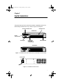
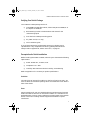
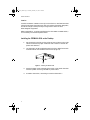
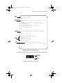
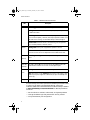
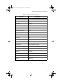
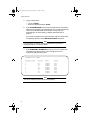
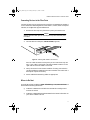
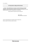
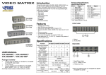
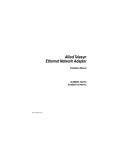
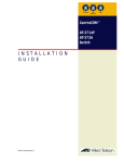
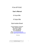
Fiber_Book Page 1 Tuesday, February 17, 1998 1:43 PM FORMULA 8200™ Fast Ethernet Fiber Workgroup Switch Installation Guide PN 613-10688-00 Rev. A Fiber_Book Page 2 Tuesday, February 17, 1998 1:43 PM Copyright 1998 Allied Telesyn International Corp. All rights reserved. No part of this publication may be reproduced without prior written permission from Allied Telesyn International Corp. FORMULA 8200 is a trademark of Allied Telesyn International Corp. Ethernet is a registered trademark of Xerox Corporation. All other product names, company names, logos or other designations mentioned herein are trademarks or registered trademarks of their respectives owners. Allied Telesyn International Corp. reserves the right to make changes in specifications and other information contained in this document without prior written notice. The information provided herein is subject to change without notice. In no event shall Allied Telesyn International Corp. be liable for any incidental, special, indirect, or consequential damages whatsoever, including but not limited to lost profits, arising out of or related to this manual or the information contained herein, even if Allied Telesyn International Corp. has been advised of, known, or should have known, the possibility of such damages. Fiber_Book Page iii Tuesday, February 17, 1998 1:43 PM Table of Contents Chapter 1 Switch Installation .........................................................................................1 Overview ..............................................................................................................2 Verifying Your Switch Package ..........................................................................3 Prerequisites for Card Installation ....................................................................3 Ventilation ....................................................................................................3 Power ............................................................................................................3 Installing the FORMULA 8200 on the Desktop ................................................4 Installing the FORMULA 8200 in the Rack ......................................................5 Attaching a Console to the Switch......................................................................6 Powering Up and Initializing the Switch...........................................................6 Connecting Devices to the Fiber Ports .............................................................11 Where to Go Next ..............................................................................................11 Sample Networking Applications .....................................................................12 Chapter 2 Troubleshooting ............................................................................................13 Areas to Check...................................................................................................13 Checking LED Status........................................................................................14 IP Addresses ......................................................................................................15 Cabling ...............................................................................................................16 Appendix A Product Specifications for the FORMULA 8200 Switch ......................17 Appendix B Technical Support Fax Order ....................................................................19 Incident Summary.............................................................................................19 Appendix C FORMULA 8200 Fiber Switch Installation Guide Feedback ..............21 Appendix D Where To Find Us ..........................................................................................23 iii Fiber_Book Page iv Tuesday, February 17, 1998 1:43 PM Fiber_Book Page 1 Tuesday, February 17, 1998 1:43 PM Chapter 1 Switch Installation This guide shows you how to install the FORMULA 8200 fiber switch from Allied Telesyn International Corp., shown in Figure 1 and Figure 2. Slot for accelerator card Expansion slot AT-8208 F/SC 10/100BASE-T NETWORK PORTS 9 Slot for uplink card 11 10/100BASE-T NETWORK PORTS 12 13 100 BASE-FX 10/100BASE-T NETWORK PORTS STATUS 1 1 POWER RESET 10 2 2 3 3 4 4 15 8201 16 10/100BASE-T NETWORK PORTS 5 GREEN - LINK YELLOW - DIAG 14 6 GREEN - ACTIVITY YELLOW - COLLISION 5 6 7 7 8 8 RESET STATUS Activity Collision POWER Link Diag RS-232 TERMINAL PORT Console port Reset button, Power LED, and Status LED Onboard module AT-8216F/SC 10/100BASE-T NETWORK PORTS 9 9 10 10 11 11 12 10/100BASE-T NETWORK PORTS 100 BASE-FX 12 13 14 13 14 15 15 16 Activity Collision 8201 16 Link Diag STATUS 100 BASE-FX 10/100BASE-T NETWORK PORTS POWER RESET 1 1 2 2 3 3 4 4 GREEN - LINK YELLOW - DIAG 10/100BASE-T NETWORK PORTS 5 GREEN - ACTIVITY YELLOW - COLLISION 6 5 RESET STATUS POWER 6 7 7 8 8 Activity Collision Link Diag RS-232 TERMINAL PORT Figure 1: The FORMULA 8200 Fiber Switch Models (AT-8208F/SC and AT-8216F/SC) Power switch Power Switch Figure 2: The FORMULA 8200 Rear Panel 1 Fiber_Book Page 2 Tuesday, February 17, 1998 1:43 PM Switch Installation Overview The FORMULA 8200 includes the following hardware and software features: ❑ Eight or sixteen 100Base-FX, full duplex, dual SC fiber ports ❑ Flow control to autosense buffer limits on the transmit port ❑ Front panel LEDs that provide operating status and a Reset button for front panel control of switch ❑ RS-232 console port interface for local switch management or Telnet support for remote switch management ❑ Rack mount or table mount capabilities ❑ Support for multiple optional hardware and port configurations: — 10/100Base-TX expansion ports — OC3 ATM uplink card — FDDI uplink card 2 ❑ Virtual LAN (VLAN) support for up to 16 VLANs ❑ Virtual routing to provide switching between VLANs ❑ Loop detection using Spanning Tree Protocol (IEEE 802.1d) ❑ Port mirroring to allow monitoring of one’s port activities from another port ❑ Support for RMON Groups 1,2,3, and 9 ❑ Simple Network Management Protocol (SNMP) agent for Management Information Bases (MIB) II and a private enterprise MIB ❑ TFTP and Zmodem support for software upgrades and backup Fiber_Book Page 3 Tuesday, February 17, 1998 1:43 PM FORMULA 8200 Fiber Switch Installation Guide Verifying Your Switch Package Your FORMULA 8200 package consists of: ❑ One FORMULA 8200 fiber switch, either the 8-port AT-8208F/SC or the 16-port AT-8216F/SC ❑ Rackmounting kit that includes brackets and screws for the rackmounting option ❑ Four feet for the desktop mounting option ❑ AC power cord (U.S.A. only) ❑ This installation guide If any of these components are damaged, contact your shipping carrier representative. If any components are missing, please phone the Allied Telesyn. Refer to Appendix D, “Where To Find Us,” on page 23. Prerequisites for Switch Installation Before installing the FORMULA 8200, make sure your site meets the following requirements: ❑ Power: 90-264 VAC, 47-63 Hz, 3-6A ❑ Temperature: 0° ~ 40°C ❑ Humidity: 85% maximum relative humidity, noncondensing Refer to Appendix A for a summary on product specifications. Ventilation The switch has an internal fan module. For the fan to function correctly, you must not block the ventilation openings which are located at the rear and the sides of the chassis. Power Power connections for each unit should be able to provide 120 VAC for North American models or 240 VAC for international models. It is advisable to use dedicated power circuits or power conditioners to supply power to the network devices. This aids in isolating network equipment from electrical power interference. 3 Fiber_Book Page 4 Tuesday, February 17, 1998 1:43 PM Switch Installation Location Install the FORMULA 8200 on a sturdy, level surface in a ventilated area that is dust free and away from heat vents, warm air exhaust from other equipment, and direct sunlight. Avoid proximity to large electric motors or other electromagnetic equipment. Refer to Appendix A, “Product Specifications for the FORMULA 8200 Switch,” for a summary of installation specifications. Installing the FORMULA 8200 on the Desktop 1. Set the switch on the flat surface. Allow at least 2 inches on the right side of the switch for proper ventilation and 5 inches in the back for power cord clearance. 2. Use the plastic screws provided to attach the four rubber feet to each marked location on the bottom of the chassis (Figure 3). 3007 Figure 3: Installing the Rubber Feet 4 3. Attach the power cord to the back of the switch. Then attach the other end of the power cord to a grounded AC power outlet. 4. Proceed to the section, “Attaching a Console to the Switch.” Fiber_Book Page 5 Tuesday, February 17, 1998 1:43 PM FORMULA 8200 Fiber Switch Installation Guide Installing the FORMULA 8200 in the Rack Caution When mounting the switch in a rack, do not stack units directly on top of one another. 1. If the rubber feet are attached, remove them. 2. Attach the mounting brackets to the side of the switch using the M4 x 8 mm screws provided (Figure 4). Caution Use only the M4 x 8 mm screws provided. Longer screws may contact the internal components, damaging the unit. Figure 4: Attaching the Mounting Brackets 3. Align the holes in the mounting brackets to the holes in the rack (Figure 5) and secure with the screws provided. Figure 5: Rackmounting the Switch 4. Attach the power cord to the back of the switch. Then attach the other end of the power cord to a grounded AC power outlet. 5. Proceed to the section, “Attaching a Console to the Switch.” 5 Fiber_Book Page 6 Tuesday, February 17, 1998 1:43 PM Switch Installation Attaching a Console to the Switch You need the following equipment: ❑ A terminal or TTY-compatible terminal, or a portable computer with a serial port and the ability to emulate a VT100 terminal ❑ A UL-listed null modem RS232 cable with a female DB9 connector for the console port on the switch and with a connector on the other end that is appropriate for your computer or terminal 1. Set the terminal protocol as follows: — — — — — — 9600 baud No parity 8 bits 1 stop bit Window terminal emulation option set to No Terminal preferences: Function, Arrow, and Control keys active 2. Connect the terminal (or a computer in terminal-emulation mode) to the switch’s console port using the RS232 cable. Then turn on the terminal. 3. Proceed to the section, “Powering Up and Initializing the Switch.” Powering Up and Initializing the Switch Power on the switch. The switch goes through a power-on self test (POST) to verify that all components are functioning properly. The console displays messages similar to the following screen: Note Report any error messages to Allied Telesyn’s Technical Support department. Refer to Appendix D, “Where To Find Us,” for contact information. 6 Fiber_Book Page 7 Tuesday, February 17, 1998 1:43 PM FORMULA 8200 Fiber Switch Installation Guide Post begins Boot POST in progress... PROM version: 1.0.10 Component tests Firmware loads Sizing DRAM (value displayed is bank size or error code)... DRAM now configured into a contiguous block: Address: ............. 0xa0000000 - 0xa07ffffc Running DRAM test... Initializing 4650 icache and dcache... Initializing PIG chip... Initializing PMIU chips... . . Boot POST complete, passing control to firmware... Loading /flash/firmware...Starting at 0x80010000... Firmware version 1.4.0 System info Vendor info Date= 11/7/97 time= 11:34:27 Restore configuration for system IP address = 0.0.0.0 Number of ports = 16 Configuration changed srm_init success Allied Telesyn International Corp. Copyright@ 1997 Allied Telesyn All rights reserved. Switch Init Success Login: Figure 6: FORMULA 8200 POST Messages 4. Observe the LEDs for normal switch operation (Figure 7 and Table 1). Activity Collision Link Diag Figure 7: Close-Up of the FX Port LEDs 7 Fiber_Book Page 8 Tuesday, February 17, 1998 1:43 PM Switch Installation Table 1: FORMULA 8200 FX LED States LED Description Status Flashing green means the system-wide operation is normal. Solid green means the switch is locked up and you probably cannot log in. Reboot the switch. Flashing amber means the switch is completing a DRAM test during a power on self test (POST); otherwise, there may be problems. Reboot. If the LED state does not change, contact Allied Telesyn’s Technical Support. Solid amber means the switch is still functioning, but with problems. Try to solve the problems; otherwise, reboot. Power Solid green means power is applied and operation is normal. Off means there is no power to the switch. Check the power cord and power source. Turn off and on. Replace the switch if LED remains unlit. Port LED: Activity Flashing or solid green means the port is receiving or transmitting traffic. Off means there is no traffic. This LED state does not indicate a problem. Port LED: Collision Port LED: Link Diag This LED is always off. It is not supported on the FORMULA 8200 fiber switch because collisions do not occur on full duplex FX ports. Solid green means the cable’s link status is good. Off means there is no link; flashing means there is a link problem. Verify cable and port speed supported on end device (FX ports are 100Mbps full duplex only). This LED is normally off. This LED is reserved for factory use. At initial startup, the switch operates at the default parameters listed in Table 2. If you want to change these settings, refer to the FORMULA 8200 User’s Guide available from Allied Telesyn’s website at www.alliedtelesyn.com/manuals.htm for detailed procedures on how to: — Set the switch’s IP address, subnet mask, and gateway address — Change the default login and password for security reasons — Verify the Ethernet port configuration 8 Fiber_Book Page 9 Tuesday, February 17, 1998 1:43 PM FORMULA 8200 Fiber Switch Installation Guide Table 2: Default Fiber Switch’s Parameters Parameter Default Value System login admin System password switch Admin Status Enabled IP Address 0.0.0.0 IP Subnet Mask Address 0.0.0.0 Default Gateway Address 0.0.0.0 Spanning Tree Protocol Enabled Port Path Cost 10 Port Priority 128 Half or Full Duplex Full duplex on FX ports Port Speed 100 Mbps on FX ports Autonegotiation Off; not applicable to FX ports Spanning Tree Priority 32768 Active Aging Time 300 seconds Hello Time 2 seconds IP RIP Mode Silent VLAN All ports to a default VLAN #1 Console 9600, 8, N, 1 9 Fiber_Book Page 10 Tuesday, February 17, 1998 1:43 PM Switch Installation 5. Log in at the prompt: — Log in as admin. — Enter the default password, switch. 6. Enter SYSTEM/SHOW and verify the firmware and IP information. Make sure the firmware version displayed on the screen matches the version of the Release Notes and the User’s Guide you will be downloading from Allied Telesyn’s website (described later on page 11). If you want to configure the IP parameters (IP address, subnet mask, and gateway address), use the BOOT/IP/CONFIG command. Note You must enter a unique IP address for the switch if you plan to manage the switch via Telnet or SNMP. 7. Enter ETHERNET/SHOW/PORT to verify your port configuration. The following screen shows the initial configuration for the FORMULA 8200 with 8 FX ports: /ETHERNET/SHOW> port Physical Port# ============== 1 2 3 4 5 6 7 8 Autoneg ======= off off off off off off off off Speed ===== 100MBPS 100MBPS 100MBPS 100MBPS 100MBPS 100MBPS 100MBPS 100MBPS Duplex ====== FULL FULL FULL FULL FULL FULL FULL FULL Note You cannot change the port settings on the display. 10 Fiber_Book Page 11 Tuesday, February 17, 1998 1:43 PM FORMULA 8200 Fiber Switch Installation Guide Connecting Devices to the Fiber Ports Connect the switch to any equipment that conforms to IEEE 802.3u standard, such as Ethernet networking devices, workstations, servers, other full duplex switches, or bridges that support 100Base FX. 1. Remove the dust caps only from the FX ports you intend to use. Caution Always leave the dust caps on unused ports to protect the fiber ports from dust. 2. Connect devices to the ports, one at a time (Figure 8). Figure 8: Attaching Fiber Cables to the FX Ports Dual SC cable connectors are keyed so you can insert them only one way. If your cable is not keyed, note that the Receive cable is on the right and the Transmit cable is on the left. 3. Verify the correct link and status condition for every port-to-device connection before proceeding to the next connection. See Table 1 for a description of port LED activity. 4. Attach additional networking cables as appropriate. Where to Go Next Go to Allied Telesyn’s website at www.alliedtelesyn.com/manuals.htm and download the following documents: ❑ FORMULA 8200 User’s Guide for the commands to configure and monitor the switch ❑ FORMULA 8200 Software Release Notes for the latest information on your switch software version 11 Fiber_Book Page 12 Tuesday, February 17, 1998 1:43 PM Switch Installation Sample Networking Applications Workgroup LAN Switching Example Router 10/100BASE-T NETWORK PORTS 100 Mbps 9 9 10 10 11 11 12 10/100BASE-T NETWORK PORTS 100 BASE-FX 12 13 14 13 14 15 15 16 8201 Activity Collision 16 Link Diag STATUS 100 BASE-FX 10/100BASE-T NETWORK PORTS POWER RESET 1 1 2 2 3 3 4 4 GREEN - LINK YELLOW - DIAG 100 Mbps 10/100BASE-T NETWORK PORTS 5 GREEN - ACTIVITY YELLOW - COLLISION 6 5 6 7 7 8 8 Activity Collision RESET STATUS Link Diag POWER RS-232 TERMINAL PORT FORMULA 8200 Server Backbone LAN Switching Example 100 Mbps 10/100BASE-T NETWORK PORTS 9 9 10 10 11 11 12 10/100BASE-T NETWORK PORTS 100 BASE-FX 12 13 13 14 14 15 15 16 Server 8201 Activity Collision 16 Link Diag STATUS 100 BASE-FX 10/100BASE-T NETWORK PORTS POWER RESET 1 1 2 2 3 3 4 4 GREEN - LINK YELLOW - DIAG 100 Mbps 10/100BASE-T NETWORK PORTS 5 GREEN - ACTIVITY YELLOW - COLLISION 5 6 6 7 7 8 8 Activity Collision RESET STATUS Link Diag POWER RS-232 TERMINAL PORT 10/100 Mbps FORMULA 8200 Switch Optional ATM Backbone Connectivity Example 155 Mbps ATM Switch FORMULA 8200 10/100BASE-T NETWORK PORTS 9 9 10 10 11 11 12 10/100BASE-T NETWORK PORTS 100 BASE-FX 12 13 14 5 6 13 14 15 15 16 Activity Collision 8201 16 Link Diag STATUS 100 BASE-FX 10/100BASE-T NETWORK PORTS POWER RESET 1 1 2 2 3 3 4 4 GREEN - LINK YELLOW - DIAG 10/100BASE-T NETWORK PORTS GREEN - ACTIVITY YELLOW - COLLISION 5 RESET STATUS POWER 6 7 7 8 8 Activity Collision Link Diag RS-232 TERMINAL PORT 155 Mbps 100 Mbps 10/100BASE-T NETWORK PORTS 9 9 10 10 11 11 12 10/100BASE-T NETWORK PORTS 100 BASE-FX 12 13 14 5 6 13 14 15 15 16 Activity Collision 8201 16 Link Diag STATUS 100 BASE-FX 10/100BASE-T NETWORK PORTS POWER RESET 1 RESET STATUS POWER 1 2 2 3 3 4 4 GREEN - LINK YELLOW - DIAG 10/100BASE-T NETWORK PORTS GREEN - ACTIVITY YELLOW - COLLISION 5 6 7 7 8 8 Activity Collision Link Diag RS-232 TERMINAL PORT FORMULA 8200 (TX ports) Servers 12 10/100 Mbps Fiber_Book Page 13 Tuesday, February 17, 1998 1:43 PM Chapter 2 Troubleshooting This chapter provides information on isolating and resolving problems with FORMULA 8200 operation. Ethernet networks tend to be fairly simple, but they can still have problems that take time to resolve. The most common problems are associated with the actual network cabling. If you have problems with a newly established network (initial setup), the trouble is most likely related to cabling or addressing. If the network has been operational for an extended period and is now beginning to have problems, the trouble is probably related to recent additions or changes to the network, or configuration settings on your switch. Note If you have trouble performing any of the steps in this chapter, or if you have questions not covered in this manual, contact Allied Telesyn’s Technical Support Department. See Appendix D, “Where To Find Us,” for contact information. Areas to Check The following pages describe the areas to check when troubleshooting the switch: ❑ LED status ❑ IP Addressing ❑ Network cabling 13 Fiber_Book Page 14 Tuesday, February 17, 1998 1:43 PM Troubleshooting Checking LED Status The switch has system LEDs (Status and Power), located on the front panel, that indicate the switch’s overall operational status. For the location of these LEDs, see the encircled area in Figure 9. 10/100BASE-T NETWORK PORTS 9 11 10/100BASE-T NETWORK PORTS 12 13 100 BASE-FX 10/100BASE-T NETWORK PORTS STATUS 1 POWER RESET 10 1 2 2 3 3 4 4 GREEN - LINK YELLOW - DIAG 14 15 16 10/100BASE-T NETWORK PORTS 5 GREEN - ACTIVITY YELLOW - COLLISION 6 5 6 7 7 8 8 RESET STATUS A POWER RS-232 TERMINAL PORT Figure 9: Switch System LEDs Additionally, each FX port has a set of LEDs to the right. For a closeup view of the FX LEDs, see Figure 10. Activity Collision Link Diag Figure 10: FX Port LEDs Table 3 describes how these LEDs report on the switch and ports’ status, and what you need to do in case of a problem. Table 3: LED States and Recommended Action LED Status Description and Action Required Flashing green means the switch’s system-wide operations are normal. Solid green means the switch software is locked up and you probably cannot log in. Reboot the switch. Flashing amber means the switch is completing a DRAM test during a power on self test (POST); otherwise, there may be problems. Reboot. If the LED state does not change, contact Allied Telesyn’s Technical Support. Solid amber means the switch is still functioning, but with problems. Try to determine the cause of the problem without rebooting the switch. If all else fails, reboot. 14 Fiber_Book Page 15 Tuesday, February 17, 1998 1:43 PM FORMULA 8200 Fiber Switch Installation Guide Table 3: LED States and Recommended Action (Continued) LED Power Description and Action Required Solid green means power is applied and the switch is functioning normally. No action is required. Off means there is no power to the switch. Check the power plug and the state of the on/off switch in the back of the unit. If On, turn it off, wait a few seconds, and turn it on. If LED remains unlit, replace the switch. Port LED: Activity Flashing or solid green means the port is receiving or transmitting traffic. No action is required. Off means there is no traffic. This state does not indicate any problem on that port. No action is required. Port LED: Collision This LED is always Off. It is not supported on the FORMULA 8200 fiber switch because collisions do not occur on full duplex FX ports. No action is required. Port LED: Solid green means the cable’s link status is good. Link Port LED: Diag Off means there is no link; flashing means there is a link problem. Verify cable and port speed supported on end device (FX ports are 100Mbps full duplex only). This LED is normally off. This LED is reserved for factory use. IP Addresses The FORMULA 8200 has a factory-assigned unique MAC address but does not have a default IP address. If you are managing the switch from a console, an IP address is not required. However, if you are managing the switch over the network (via SNMP or Telnet), the switch must have a valid IP address. Assign a unique IP address to the switch by using the BOOT/IP/CONFIG command. See the FORMULA 8200 User’s Guide, available from www.alliedtelesyn.com/manuals.htm, for more details. 15 Fiber_Book Page 16 Tuesday, February 17, 1998 1:43 PM Troubleshooting Cabling The fiber media adapter for the 100Base-FX port uses only multimode 62.5/125 micron, 1300 nm fiber cable. The 100Base-FX media adapter is not supported on single-mode fiber. All fiber port connections use dual SC connectors. 16 Fiber_Book Page 17 Tuesday, February 17, 1998 1:43 PM Appendix A Product Specifications for the FORMULA 8200 Switch Network Protocol Fast Ethernet Standards Supported IEEE 802.1d IEEE 802.3u, 100Base-X Data Rate 100 Mbps multimode fiber Hardware Architecture Processor MIPS 4650 Flash memory 2 Mbytes Processor DRAM 8 Mbytes Physical Specifications Dimensions Weight 3.5”H x 17” W x 18”D (8.97 x 43.6 x 46.2 cm) 19 lbs (8.6 kg) Electrical Specifications Input line frequency 47-63 Hz Input voltage 90-264 VAC, auto-selectable Input current 3-6 Amps Environmental Specifications Operating temperature 0˚ to 40˚ C (32˚ to 104˚ F) Storage temperature –20˚ to 60˚ C (–18˚ to 148˚ F) Operating humidity 85% maximum relative humidity, noncondensing Storage humidity 95% maximum relative humidity, noncondensing Operating altitude 0 to 10,000 ft. 17 Fiber_Book Page 18 Tuesday, February 17, 1998 1:43 PM Product Specifications for the FORMULA 8200 Switch Electromagnetic Immunity RF susceptibility EN61000, Level 4/3 Electric Fast Transitions EN61000, Level 4/4 Electrostatic discharge (ESO) EN61000, Level 4/2 Electromagnetic Emissions FCC Class A digital devices En 55 022 Class A VCCI Class 2 ITE Safety Agency Approvals UL/cUL Listed (UL1950) CSA Accepted TUV Licensed (IEC950-A2, 1993) Meets CE Conformity Standards (CE on file) 18 Fiber_Book Page 19 Tuesday, February 17, 1998 1:43 PM Appendix B Technical Support Fax Order Name___________________________________________________________________ Company ________________________________________________________________ Address _________________________________________________________________ City ________________________ State/Province ________________________________ Zip/Postal Code ___________________ Country ________________________________ Phone _______________________________ Fax ________________________________ Incident Summary Model number of Allied Telesyn product I am using ______________________________ Network software products I am using _________________________________________ _______________________________________________________________________ Brief summary of problem __________________________________________________ _______________________________________________________________________ Conditions (list the steps that led up to the problem) _____________________________ _______________________________________________________________________ _______________________________________ _______________________________ Detailed description (use separate sheet, if necessary) _______________________________________________________________________ _______________________________________ _______________________________ _______________________________________________________________________ When completed, fax this sheet to the appropriate Allied Telesyn office. Fax numbers can be found on page 23. 19 Fiber_Book Page 20 Tuesday, February 17, 1998 1:43 PM Fiber_Book Page 21 Tuesday, February 17, 1998 1:43 PM Appendix C FORMULA 8200 Fiber Switch Installation Guide Feedback Please tell us what additional information you would like to see discussed in the guide. If there are topics you would like information on that were not covered in the guide, please photocopy this page, answer the questions and fax or mail this form back to Allied Telesyn International Corp. The mailing address and fax number are at the bottom of the page. Your comments are valuable when we plan future revisions of the guide. I found the following the most valuable __________________________________ ______________________________________________________________________ ______________________________________________________________________ ______________________________________________________________________ ______________________________________________________________________ I would like the following more developed ________________________________ ______________________________________________________________________ ______________________________________________________________________ ______________________________________________________________________ ______________________________________________________________________ I would find the guide more useful if ____________________________________ ______________________________________________________________________ ______________________________________________________________________ ______________________________________________________________________ Please fax or mail your feedback. Fax to 1-425-481-3790. Or mail to: Allied Telesyn Technical Communications Department 19015 North Creek Parkway Bothell, WA 98011 USA 21 Fiber_Book Page 22 Tuesday, February 17, 1998 1:43 PM Fiber_Book Page 23 Tuesday, February 17, 1998 1:43 PM Appendix D Where To Find Us For Technical Support or Service Location Phone Fax Americas United States, Canada, Mexico, Central America, South America 1 (800) 428-4835 1 (425) 481-3790 Asia Singapore, Taiwan, Thailand, Malaysia, Indonesia, Korea, Philippines, China, India (+65) 3815-613 (+65) 3833-830 Australia Australia, New Zealand (612) 416-0619 (612) 416-9764 France France, Belgium, Luxembourg, The Netherlands, Middle East, Africa (+33) 1-60-92-15-32 (+33) 1-69-28-37-49 Germany Germany, Switzerland, Austria, Eastern Europe (+49) 30-435-900-126 (+49) 30-435-70-650 Hong Kong (+852) 2-529-4111 (+852) 2 529-7661 Italy Italy, Spain, Portugal, Greece, Turkey, Israel (+39) 2-416047 (+39) 2-419282 Japan (+81) 3-3443-5640 (+81) 3-3443-2443 United Kingdom United Kingdom, Denmark, Norway, Sweden, Finland, Iceland (+44) 1-235-442560 (+44) 1-235-442490 Technical Bulletin Board Service 1 (425) 483-7979 Technical Support E-mail Address [email protected] CompuServe Go ALLIED World Wide Web http://www.alliedtelesyn.com FTP Server Address: ftp.alliedtelesyn.com [lowercase letters] Login: anonymous [lowercase letters] Password: your e-mail address [requested by the server at login] For Information Regarding Allied Telesyn International Allied Telesyn International 19015 North Creek Parkway Bothell, WA 98011 Tel: 1 (425) 487-8880 Fax: 1 (425) 489-9191 Allied Telesyn International 950 Kifer Road Sunnyvale, CA 94086 Tel: 1 (800) 424-4284 (USA and Canada) Fax: 1 (408) 736-0100 23 Fiber_Book Page 24 Tuesday, February 17, 1998 1:43 PM Where To Find Us For Sales Information Australia United States Lindfield, NSW Tel: (612) 416-0619, Fax: (612) 416-9764 Scottsdale, AZ Tel: (602) 423-7087 Fax: (602) 423-7088 Los Angeles, CA Tel: (310) 412-8684, Fax: (310) 412-8685 Mission Viejo, CA Tel: (714) 699-0628, Fax: (714) 699-0276 San Diego, CA Tel: (619) 279-3899, Fax: (619) 279-3897 Santa Ana, CA Tel: (714) 838-0434, Fax: (714) 838-9721 Clearwater, FL Tel: (813) 726-0022, Fax: (813) 726-0234 Norcross, GA Tel: (770) 448-7214, Fax: (770) 448-2600 Reading, MA Tel & Fax: (617) 944-3492 Eden Prairie, MN Tel: (612) 829-7506, Fax: (612) 903-5284 St. Louis, MO Tel: (314) 894-6160, Fax: (314) 894-3773 Dover, NH Tel: (603) 743-3010, Fax: (603) 743-6327 Plaistow, NH Tel: (603) 382-0815, Fax: (603) 382-0818 Portsmouth, NH Tel: (603) 431-6461, Fax: (603) 431-1649 Morrisville, NC Tel: (919) 468-0831, Fax: (919) 468-0829 Lake Oswego, OR Tel: (503) 699-3130, Fax: (503) 636-6575 Austin, TX Tel: (512) 261-6378, Fax: (512) 261-6379 Dallas, TX Tel: (214) 365-9471, Fax: (214) 365-9472 San Antonio, TX Tel: (210) 646-8744 Vienna, VA Tel: (703) 506-0196, Fax: (703) 506-1986 Canada Rexdale, Ontario Tel: (416) 675-6738, Fax: (416) 675-0057 Richmond, British Columbia Tel: (604) 244-0678, Fax: (604) 270-3644 England Abingdon, Oxon Tel: (+44) 1235-442500, Fax: (+44) 1235-442590 France Les Ulis Tel: (+33) 1-60921525, Fax: (+33) 169-28-37-49 Germany Berlin Tel: (+49) 30-435-90-00, Fax: (+49) 30-435-706-50 Freising Tel: (+49) 8161-9906-0, Fax: (+49) 8161-9906-22 Hong Kong Mongkok Tel: (+852) 2-529-4111, Fax: (+852) 2-529-7661 Italy Milano Tel: (+39) 2-416047, Fax: (+39) 2-419282 Japan Machida-shi, Tokyo Tel: (+81) 427-21-8141, Fax: (+81) 427-21-8848 Yodogawa-ku, Osaka Tel: (+81) 6-391-6310, Fax: (+81) 6-391-6325 Singapore Tel: (+65) 383-3832, Fax: (+65) 383-3830 24