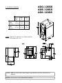
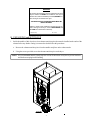
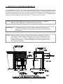
1
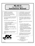
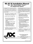
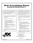
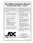
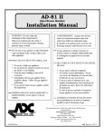
AD-120ES
(Gas/Electric/Steam)
Exhaust Addendum
WARNING: For your safety the
information in this manual must be
followed to minimize the risk of fire or
explosion or to prevent property damage,
personal injury or death.
AVERTISSEMENT: Assurez-vous de bien
suivre les instructions données dans cette
notice pour réduire au minimum le risque
d’incendie ou d’explosion ou pour éviter tout
dommage matériel, toute blessure ou la mort.
Do not store or use gasoline or other flammable
vapor and liquids in the vicinity of this or any
other appliance.
Ne pas entreposer ni utiliser d’essence ni
d’autres vapeurs ou liquides inflammables dans
le voisinage de cet appareil ou de tout autre
appareil.
WHAT DO YOU DO IF YOU SMELL GAS
* Do not try to light any appliance.
* Do not touch any electrical switch; do not use
any phone in your building.
* Clear the room, building or area of all
occupants.
* Immediately call your gas supplier from a
neighbor's phone. Follow the gas supplier's
instructions.
* If you cannot reach your gas supplier, call the
fire department.
Installation and service must be performed by a
qualified installer, service agency or the gas
supplier.
QUE FAIRE SI VOUS SENTEZ UNE ODEUR
DE GAZ:
* Ne pas tenter d’allumer d’appareil.
* Ne touchez à aucun interrupteur. Ne pas
vous servir des téléphones se trouvant dans
le bâtiment où vous vous trouvez..
* Évacuez la pièce, le bâtiment ou la zone.
* Appelez immédiatement votre fournisseur de
gaz depuis un voisin. Suivez les instructions
du fournisseur.
* Si vous ne pouvez rejoindre le fournisseur
de gaz, appelez le service des incendies.
L’installation et l’entretien doivent être assurés
par un installateur ou un service d’entretien
qualifié ou par le fournisseur de gaz.
For replacement parts, contact the distributor from which the dryer
was purchased or
American Dryer Corporation
88 Currant Road
Fall River MA 02720-4781
Telephone: (508) 678-9000 / Fax: (508) 678-9447
E-mail: [email protected]
021899DMG/cj
ADC Part No. 113082
Retain This Addendum In A Safe Place For Future Reference
American Dryer Corporation products embody advanced concepts in engineering, design, and safety. If this product is
properly maintained, it will provide many years of safe, efficient, and trouble-free operation.
ONLY qualified technicians should service this equipment.
OBSERVE ALL SAFETY PRECAUTIONS displayed on the equipment or specified in the installation/operator's manual
included with the dryer.
The following “FOR YOUR SAFETY” caution must be posted near the dryer in a prominent location.
FOR YOUR SAFETY
POUR VOTRE SÉCURITÉ
Do not store or use gasoline or
other flammable vapors or liquids
in the vicinity of this or any other
appliance.
Ne pas entreposer ni utiliser d’essence
ni d’autres vapeurs ou liquides
inflammables dans le voisinage de cet
appareil ou de yout autre appareil.
We have tried to make this manual as complete as possible and hope you will find it useful. ADC reserves the right to make
changes from time to time, without notice or obligation, in prices, specifications, colors, and material, and to change or
discontinue models.
Important
For your convenience, log the following information:
DATE OF PURCHASE
MODEL NO.
AD-120ES
DISTRIBUTORS NAME
Serial Number(s)
Replacement parts can be obtained from your distributor or the ADC factory. When ordering replacement parts from the
factory, you can FAX your order to ADC at (508) 678-9447 or telephone your orders directly to the ADC Parts Department at
(508) 678-9000. Please specify the dryer model number and serial number in addition to the description and part number, so
that your order is processed accurately and promptly.
The illustrations on the following pages may not depict your particular dryer exactly. The illustrations are a composite of the
various dryer models. Be sure to check the descriptions of the parts thoroughly before ordering.
“IMPORTANT NOTE TO PURCHASER”
Information must be obtained from your local gas supplier on the instructions
to be followed if the user smells gas. These instructions must be posted in a
prominent location near the dryer.
Table of Contents
A.
B.
C.
D.
SPECIFICATIONS.......................................................................................................................... 2
UNPACKING AND SETTING UP .................................................................................................. 3
DRYER ENCLOSURE REQUIREMENTS .................................................................................... 4
EXHAUST REQUIREMENTS ....................................................................................................... 5
ADG-120ES
ADE-120ES
ADS-120ES
A. SPECIFICATIONS
GAS AND
72 KW
ELECTRIC
STEAM AND
80 KW
ELECTRIC
EXHAUST
D UCT
D IA.
D IM.
"A"
DIM.
"A"
14"
30.5 cm
11-1/4"
28.6
9-1/2"
24.1 cm
16"
40.6 cm
9"
22.9 cm
9"
22.9 cm
NOTE: OPERATING HEIGHT OF STEAM DRYER
is 89 inches (226.1 cm).
NOTE: ADC reserves the right to make changes in specifications at any time, without notice or
obligation.
NOTE: Duct work size varies with installation conditions.
2
WARNING
An exhaust duct transition piece is shipped inside of the
dryer’s tumbler and MUST be installed on the dryer’s
exhaust duct, with the hardware provided, BEFORE location venting is connected to the dryer.
THIS EXHAUST DUCT TRANSITION PIECE MUST BE
INSTALLED FIRST!
Failure to observe this installation requirement may result in damage to the dryer, create a FIRE HAZARD and
will VOID the manufacturer’s warranty.
012999JEV-GS/cj
P/N: 114092
B. UNPACKING and SETTING UP
1. Inside the tumbler of this dryer there is an exhaust transition piece that must be installed on the outlet of the
exhaust before any further venting is connected to do this follow this procedure:
a. Remove the exhaust transition piece from the tumbler and place on the exhaust outlet.
b. Using the screws provided secure the exhaust transition piece to the dryer.
NOTE: It is recommended that this joint be taped as well as all other duct work joints to prevent moisture
and lint from escaping into the building.
3
C. DRYER ENCLOSURE REQUIREMENTS
It is recommended that the rear of the dryer be positioned approximately three (3) feet (36-inches) from the
nearest obstruction (i.e., wall) for ease of installation, maintenance, and service. Bulkheads and partitions should
be made from noncombustible materials. The clearance between the bulkhead header and the dryer must be a
minimum of 4 inches and must not extend more than 4 inches to the rear of the dryer front. The bulkhead facing
must not be closed in all the way to the top of the dryer. A 2-inch clearance is required.
NOTE: Bulkhead facing should not be installed until after dryer is in place. Ceiling area
must be located a minimum of 12 inches above the top of the dryer.
IMPORTANT: Even though a minimum of only 12 inches is required, 18 inches or more is
suggested, for steam dryers and especially in cases where sprinkler heads are
over the dryers.
NOTE: When fire sprinkler systems are located above the dryers, a minimum of 18 inches
above the dryer console (module) is suggested. Dryers may be positioned side wall
to side wall however, 1 or 2-inches is suggested between dryers (or wall) for ease of
installation and maintenance. Allowances must be made for the opening and closing
of the control and lint doors.
4
D. EXHAUST REQUIREMENTS
1. GENERAL EXHAUST DUCT WORK INFORMATION
Exhaust duct work should be designed and installed by a qualified professional. Improperly sized duct
work will create excessive back pressure which results in slow drying, increased use of energy,
overheating of the dryer, and shutdown of the burner by the airflow (sail) switches, burner hi-limits, or
basket (tumbler) hi-heat thermostats.
CAUTION: DRYER MUST BE EXHAUSTED TO THE OUTDOORS.
CAUTION: IMPROPERLY SIZED OR INSTALLED EXHAUST DUCT WORK CAN
CREATE A POTENTIAL FIRE HAZARD.
NOTE: When a dryer is exhausted separately, it is recommended that a back draft damper be
installed.
NOTE: When dryers are exhausted into a multiple (common) exhaust line, each dryer must be
supplied with a back draft damper.
The exhaust duct work should be laid out in such a way that the duct work travels as directly as
possible to the outdoors with as few turns as possible. Single or independent dryer venting is
recommended. When single dryer venting is used, the duct work from the dryer to the outside exhaust
outlet should not exceed twenty(20) feet. In the case of multiple (common) dryer venting, the distance
from the last dryer to the outside exhaust outlet should not exceed twenty(20) feet. The shape of the
duct work is not critical so long as the minimum cross section area is provided. It is suggested that the
use of 90º turns in ducting be avoided; use 30º and/or 45º angles instead. The radius of the elbows should
preferably be 1-1/2 times the diameter of the duct. Including basket/dryer elbow connections or elbows
used for outside protection from the weather, no more than one (1) elbow should be used for a horizontal
exhaust duct run and no more than three (3) for a vertical exhaust duct run. If more elbows are used, the
cross section area of the duct work must be increased in proportion to number of elbows added.
ALL duct work should be smooth inside with no projections from sheet metal screws or other obstructions
which will collect lint. When adding ducts, the ducts to be added should overlap the duct to which it is connected.
ALL duct work joints must be taped to prevent moisture and lint from escaping into the building. Additionally,
inspection doors should be installed at strategic points in the exhaust duct work for periodic inspection and cleanout of lint from the duct work.
IMPORTANT: Exhaust back pressure measured by a manometer at the dryer exhaust duct area must
not exceed 0.3 inches of water column.
5
NOTE: Where the exhaust duct work passes through a wall, ceiling, or roof made of
combustible materials, the opening must be 2-inches larger (all the way around) than
the duct. The duct must be centered within this opening.
a.Outside Duct Work Protection
1) To protect the outside end of horizontal duck work from the weather, a 90° elbow bent downward
should be installed where the exhaust exits the building. If the exhaust duct work travels vertically
up through the roof, it should be protected from the weather by using a 180° turn to point the
opening downward. In either case, allow at least twice the diameter of the duct between the duct
opening and the nearest obstruction.
IMPORTANT: DO NOT use screens or caps on the outside of opening of exhaust duct work.
6
2. SINGLE DRYER VENTING
Where possible, it is suggested to provide a separate exhaust duct for each dryer. The exhaust duct
should be laid out in such a way that the duct work travels as directly as possible to the outdoors with as
few turns as possible. It is suggested that the use of 90° turns in ducting be avoided; use 30° and/or 45°
angles instead. The shape of the exhaust duct work is not critical so long as the minimum cross section
area is provided.
IMPORTANT: Minimum duct size for a gas dryer or 72 Kw electric dryer is 14 inches for
a round duct or 12.50" for a square duct. The minimum duct size for a
steam dryer or 80 Kw electric dryer is 16 inches for a round duct or
14.50" x 14.50" for a square duct. Duct size must not be reduced anywhere
down stream of dryer.
IMPORTANT: Exhaust back pressure measured by a manometer at each basket (tumbler)
exhaust duct area should not exceed 0.3 inches of water column.
It is suggested that the duct work from each dryer (minimum 14 inches for a gas dryer or 72 Kw electric
dryer and 16 inches for a steam dryer or 80 Kw electric dryer) not exceed twenty (20) feet with no more
than one (1) elbow should be used for a horizontal exhaust duct run and no more than three (3) for a
horiztonal duct run (including dryer connections and outside exhaust outlets). If the duct work exceeds
twenty (20) feet or has numerous elbows, the cross section area of the duct work must be increased in
proportion to the length and number of elbows in it. In calculating duct size, the cross section area of a
square or rectangular duct must be increased by twenty (20) percent for each additional twenty (20) feet.
The diameter of a round exhaust duct should be increased ten (10) percent for each additional fifteen (15)
feet. Each 90° elbow is equivalent to an additional thirty (30) feet, and each 45° elbow is equivalent to an
additional fifteen (15) feet.
7
IMPORTANT: For extended duct work runs, the cross section area of the duct can only be
increased to an extent. When the duct work approaches the maximum limits as
noted in this manual, a professional heating venting air conditioning (HVAC)
firm should be consulted for proper venting information.
ALL duct work should be smooth inside with no projections from sheet metal screws or other obstructions
which will collect lint. When adding ducts, the duct to be added should overlap the duct to which it is to be
connected. ALL duct work joints must be taped to prevent moisture and lint from escaping into the building.
Inspection doors should be installed at strategic points in the exhaust duct work for periodic inspection and
clean-out of lint from the duct work.
NOTE: Where the exhaust duct passes through a wall, ceiling, or roof made of combustible
materials, the opening must be 2-inches larger (all the way around) than the duct.
The duct must be centered within this opening.
a. Outside Duct Work Protection
1) To protect the outside end of horizontal duct work from the weather, a 90° elbow bent downward
should be installed where the exhaust exits the building. If the exhaust duct work travels vertically
up through the roof, it should be protected from the weather by using a 180° turn to point the opening
downward. In either case, allow at least twice the diameter of the duct between the duct opening and
nearest obstruction.
IMPORTANT: DO NOT use screens, louvers, or caps on the outside of opening of exhaust duct
work.
3. MULTIPLE DRYER (COMMON) VENTING
If it is not feasible to provide separate exhaust ducts for each dryer, ducts from individual dryers may be
channeled into a "common main duct". The individual ducts should enter the bottom or side of the main
duct at an angle not more than 45° in the direction of air flow and should be spaced at least 48-3/8 inches
apart. The main duct should be tapered, with the diameter increasing before each individual 14-inch
(minimum for gas dryers or 72 Kw electric dryers) or 16-inch (minimum for steam dryers or 80 Kw electric
dryers) duct is added.
IMPORTANT:
The AD-120ES is not provided with a back draft damper. When exhausted into
a multiple (common) exhaust line, a back draft damper must be installed at
each dryer duct.
IMPORTANT: No more than four (4) dryers should be connected to one main common duct.
8
The main duct may be any shape or cross sectional area, so long as the minimum cross section area is provided.
The illustrations on pages 10 and 11 show the minimum cross section area for multiple dryer round or square
venting. These figures must be increased 10 square inches when rectangular main ducting is used, and the ratio
of duct width to depth should not be greater than 3-1/2 to 1. These figures must be increased in proportion if the
main duct run to the last dryer to where it exhausts to the outdoors is unusually long (over twenty [20] feet) or has
numerous elbows (more than one [1] elbow) in it. In calculating duct work size, the cross section area of a square
or rectangular duct must be increased twenty (20) percent for each additional twenty (20) feet. The diameter of
a round exhaust must be increased ten (10) percent for each additional twenty (20) feet. Each 90° elbow is
equivalent to an additional thirty (30) feet, and each 45º elbow is equivalent to an additional fifteen (15) feet..
IMPORTANT: For extended duct work runs, the cross section area of the duct work can only be
increased to an extent. When the duct work approaches the maximum limits as noted
in this manual, a professional HVAC firm should be consulted for proper venting
information.
IMPORTANT: Exhaust back pressure measured by a manometer at each dryer exhaust duct area
should not exceed 0.3 inches of water column.
The duct should be smooth inside with no projections from sheet metal screws or other obstructions which will
collect lint. When adding ducts, the duct to be added should overlap the duct to which it is to be connected.
ALL duct work joints must be taped to prevent moisture and lint from escaping into the building. Inspection
doors should be installed at strategic points in the exhaust duct work for periodic inspection and clean-out of
lint from the duct work.
NOTE: Where the exhaust passes through a wall, ceiling, or roof made of combustible materials,
the opening must be 2 inches larger (all the way around) than the duct. The duct must
be centered within this opening.
a. Outside Duck Work Protection
1) To protect the outside end of horizontal duct work from the weather, a 90° elbow bent downward
should be installed where the exhaust exits the building. If the exhaust duct work travels vertically
up through the roof, it should be protected from the weather by using a 180° turn to point the opening
downward. In either case, allow at least twice the diameter of the duct between the duct opening and
nearest obstruction.
IMPORTANT: DO NOT use screens, louvers, or caps on the outside of opening of exhaust
duct work.
9
MULTIPLE DRYER VENTING (ADG-120 AND ADE-120) WITH 72 KW ELECTRIC OVEN)
WITH 14" DIAMETER (2,150 CFM) EXHAUST CONNECTIONS AT COMMON DUCT
MULTIPLE DRYER VENTING (ADE-120 WITH 80 KW ELECTRIC OVEN)
WITH 16" DIAMETER (2,500 CFM) EXHAUST CONNECTIONS AT COMMON DUCT
10
MULTIPLE DRYER VENTING (ADS-120)
WITH 16" DIAMETER (2,750 CFM) EXHAUST CONNECTIONS AT COMMON DUCT
11
ADC 113082
1- 02/24/99-100
4- 05/09/00-150
2- 03/30/99-250
5- 10/02/00-150
3* 04/25/00-17