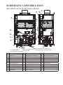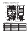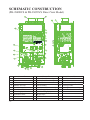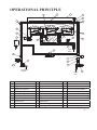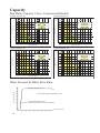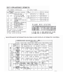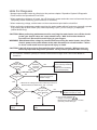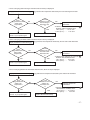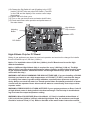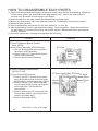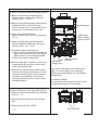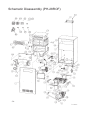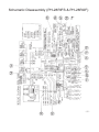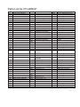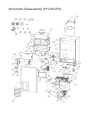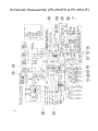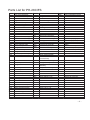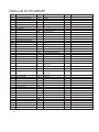
1
R
Tankless Gas Water Heaters
PH-28RIFSN; PH-28CIFSN (Indoor) (NAT. Gas)
PH-28RIFSP; PH-28CIFSP (Indoor) (L.P. Gas)
PH-28ROFN; PH-28COFN (Outdoor) (NAT. Gas)
PH-28ROFP; PH-28COFP (Outdoor) (L.P. Gas)
PH-28RDVSN; PH-28CDVSN (Direct Vent) (NAT. Gas)
PH-28RDVSP; PH-28CDVSP (Direct Vent) (L.P. Gas)
(R: Residentail Model; C: Commercial Model)
Indoor Water Heater
Outdoor Water Heater
Direct Vent Water Heater
DESIGN
CERTIFIED
CER
TIFIED
®
Engineering Handbook
R
WARNING: If the information in these instructions is not followed
exactly, a fire or explosion may result causing property damage,
personal injury or death.
- Do not store or use gasoline or other flammable vapors and liquids in the
vicinity of this or any other appliance. To do so may result in an explosion or fire.
- WHAT TO DO IF YOU SMELL GAS
* Do not try to light any appliance.
* Do not touch any electrical switch; do not use any phone in your building.
* Immediately call your gas supplier from a neighbor's phone. Follow the gas
supplier's instructions.
* If you cannot reach your gas supplier, call the fire department.
* Do not return to your home until authorized by the gas supplier or fire department.
- Installation and service must be performed by a qualified installer, service
agency or the gas supplier.
WARNING: Improper installation, adjustment, alternation, service or maintenance
can cause property damage, personal injury, or death. For assistance or additional
information, consult with a qualified distributor.
WARNING: The content on this manual is intended for use by qualified service
personnel ONLY.
Table of Contents
Page
Specifications ................................................................. 3
External Dimensions ...................................................... 4 ~ 5
Schematic Construction ................................................. 6 ~ 8
Operational Principle ..................................................... 9 ~ 12
Capacity ......................................................................... 13 ~ 14
Wiring Diagram ............................................................. 15
Operational Flow Chart & Maintenance Information.... 16
Diagnostic Points ........................................................... 17 ~ 22
Hints for Diagnosis ........................................................ 23 ~ 34
Adjustment ..................................................................... 35 ~ 47
How to Disassemble Each Parts ..................................... 48 ~ 52
Schematic Disassembly and Parts List .......................... 53 ~ 67
-2-
SPECIFICATIONS (Approx.)
Model
Purpose
Rated Gas Input
(Btu/Hr.)
Dimensions (in.)
Net Weight (lbs.)
Installation
Working Water Pressure
Minimum Water Flow
Maximum Flow Rate
Gas Connection
Water Connection
Vent Size
Max. Vent Length
Efficiency Rating
Energy Factor
Inlet Gas Pressure
before water heater
Hot Water Supply
Electrical Portion
Safety Devices
Freeze Protection
Optional Accessory
Temp. Rise (ºF)
Water Flow (GPM)
PH-28RIFSN (NAT)
PH-28RIFSP (L.P.)
PH-28CIFSN (NAT)
PH-28CIFSP (L.P.)
PH-28ROFN (NAT)
PH-28RDVSN (NAT)
PH-28ROFP (L.P.)
PH-28RDVSP (L.P.)
PH-28COFN (NAT)
PH-28CDVSN (NAT)
PH-28COFP (L.P.)
PH-28CDVSP (L.P.)
Domestic Hot Water Supply & Circulating
19,000 (Min.)
19,000 (Min.)
19,000 (Min.)
199,900 (Max.)(Modulating) 199,900 (Max.)(Modulating) 199,900 (Max.)(Modulating)
14 7/8 (W) x 25 3/8 (H) x 11 1/8 (D)
65
Indoor Wall Mounting Type Outdoor Wall Mounting
Direct Vent Indoor Wall
Can be vented either horiType
Mounting Type
zontally or vertically
Can be vented either horizontally or vertically
14 psi ~ 150 psi
0.66 GPM
7.4 GPM at 45ºF Temperature Rise
3/4” NPT Female (w/supplied Gas Shutoff Valve)
3/4” NPT Male
4” Special Venting
N/A (Outdoor Installation)
4” Special Venting
(Category III)
(Category III)
37.5 Feet Three 90º Elbow
N/A (Outdoor Installation)
37.5 Feet Three 90º Elbow
84%
0.82
Natural Gas: Min. 4.0” w.c. Max. 10.5” w.c.
L.P. Gas:
Min. 8.0” w.c. Max. 14.0” w.c. (Do not exceed maximum pressure.)
Factory Setting
100ºF
Adjusting Range
R:100ºF ~ 120ºF (140ºF); C: 100°F ~ 180°F
Max. Setting
Up to 140ºF(R) or 180°F(C)(w/ Main Remote Control &
Dip Switch Adj.)
Electrical Rating
120VAC/60Hz, Less than 2 Amps
Power Supply Cord
3 Pin Power Supply Cord 10 Feet (Indoor & Direct Vent)
Oxygen Depletion Safety
Sensing Burner (Indoor & Direct Vent)
Over Heat Limiter
Film Type for Entire Heat Exchanger
Flame Failure Safety
Flame Rod Type
Minus 30ºF (Without Wind-Chill Factor)
First Bath Remote Control (USC1-117); Second Bath Remote Control (USC2-117)
DUOnex ™ for 2-Unit Manifolding
MIC-180 for Multi-Unit System Controller (2 to 6 units); MICS-180 for Expansion Board
(Up to 20 units); MIC Communication Cables (16, 32 & 65 feet)
High Altitude Adjustment Chips for use at altitudes above 3,280 feet, and up to 9.840 feet
Hot Water Flow Rate and Temperature Rise
45
50
60
70
80
7.4
6.7
5.6
4.8
4.2
90
3.7
100
3.4
Note: Special Venting: The adapter, vent pipe, elbow, vent terminal, etc. Should be UL 1738 Certified Category III Stainless
Steel Venting Material (e.g. AL29-4C). “B” vent is not permitted.
-3
Since we are constantly improving our products, all specifications are subject to change without notice.
-
EXTERNAL DIMENSIONS
14.96” (380mm)
5.12” (130mm)
Ø4” (101.6mm)
1.89” (48mm)
1.97” (50mm)
27.36” (695mm)
25.39” (645mm)
3.45”(87mm)
(PH-28RIFS & PH-28CIFS Indoor Model)
WIRING HOLE
1.57”
(40mm)
POWER SUPPLY CORD HOLE 6.34” (161mm) 6.34” (161mm)
COLD WATER INLET
GAS INLET
3/4"NPT(M)
(W/Supplied Gas Shutoff Valve)
5.79” (147mm)
6.81” (173mm)
4.69” (119mm)
1.93” (49mm)
8.39” (213mm)
3/4"NPT(M)
0.39” (10mm)
11.10” (282mm)
2.52” 4.17” (106mm)
(64mm)
HOT WATER OUTLET
3/4"NPT(M)
5.51”
(140mm)
0.73”
(18.5mm)
3.19”
(81mm)
(PH-28ROF & PH-28COF Outdoor Model)
14.29” (363mm)
6.10” (155mm)
POWER SUPPLY CORD HOLE
8.39” (213mm)
4.69” (119mm)
1.93” (49mm)
HOT WATER OUTLET
3/4"NPT(M)
0.59” (15mm)
1.73” (44mm)
9.02” (229mm)
11.10” (282mm)
WIRING HOLE
5.79” (147mm)
6.81” 173mm)
COLD WATER INLFT
3/4"NPT(M)
1.97”
(50mm)
1.57”
(40mm)
1.97”
(50mm)
1.89”
(48mm)
6.30” (160mm)
-4-
0.59” (15mm)
8.17”(207mm)
8.82”(224mm)
9.02’ (229mm)
0.43”
(11mm)
25.39” 645mm)
26.46” (672mm)
0.33”
(8mm)
27.36” (695mm)
2.13” (54mm)
14.96” (380mm)
5.12” (130mm)
3.54” (90mm)
2.52”
4.17”
5.51” (64mm) (106mm)
(140mm)
GAS INLET
3/4"NPT(M)
(W/Supplied Gas Shutoff Valve)
0.39”
(10mm)
EXTERNAL DIMENSIONS
14.96” (380mm)
5.12” (130mm)
Ø4” (101.6mm)
1.97” (50mm)
25.39” (645mm)
5.12”
(130mm)
1.89” (48mm)
POWER SUPPLY CORD HOLE
1.57
COLD WATER INLFT
WIRING HOLE
6.34” (161mm) 6.34” (161mm)
5.79” (147mm)
8.39” (213mm)
4.69” (119mm)
1.93” (49mm)
3/4"NPT(M)
6.81” (173mm)
27.36” (695mm)
3.45
(PH-28RDVS & PH-28CDVS Direct Vent Model)
0.39” (10mm)
11.10” (282mm)
GAS INLWR
3/4"NPT(M)
(W/Supplied Gas Shutoff Valve)
2.52” 4.17”
(64mm)(106mm)
HOT WATER OUTLET
3/4"NPT(M)
5.51”
(140mm)
(Remote Control)
PRIORITY INDICATOR
4 3/4” (120mm)
1 7/8” 46mm)
7/8” (21mm)
LED DISPLAY
TEMPERATURE
ADJUSTMENT
BUTTON
PRIORITY
°F
POWER ON/OFF
INDICATOR
POWER
ON/OFF
3 1/4” (83.5mm)
4 3/4” (120mm)
COMBUSTION
INDICATOR
POWER ON/OFF
BUTTON
-5-
SCHEMATIC CONSTRUCTION
(PH-28RIFS & PH-28CIFS Indoor Model)
4
2
1
26
6
8
5
7
10
14
13
12
11
9
19
15
17
3
16
18
24
20
22
25
21
23
Gas Connection 3/4” NPT (F)
Water Inlet Connection
(W/Supplied Gas Shutoff Valve)
Hot Water Outlet
3/4” NPT (M)
Connection 3/4” NPT (M)
No.
1
2
3
4
5
6
7
8
9
10
-6-
Name of Parts
Front Cover
Back Cover
Air Filter Assembly
Exhaust Flue Top
Heat Exchanger
Heat Transfer Coil
Water Supply Coil
Turbulence Plate
Inner Case
Main Burner
No.
11
12
13
14
15
16
17
18
19
20
Name of Parts
Sensing Burner Assembly
Orifice Stand L Assembly
Orifice Stand R Assembly
Electrode
Fan Assembly
Gas Control Valve Assembly
Water Supply Pipe
Hot Water Supply Pipe
Bypass Pipe
Gas Connection
No.
21
22
23
24
25
26
Name of Parts
Water Inlet Connection
Hot Water Outlet Connection
Drain Valve
Water Control Body Assy.
PC Board
Film Type OHL
SCHEMATIC CONSTRUCTION
(PH-28ROF & PH-28COF Outdoor Model)
2
1
4
25
6
8
5
7
10
11
13
9
12
18
14
16
15
17
3
23
24
19
21
20
Gas Connection 3/4” NPT (F)
(W/Supplied Gas Shutoff Valve)
22
Water Inlet Connection
Hot Water Outlet
Connection 3/4” NPT (M) 3/4” NPT (M)
No.
1
2
3
4
5
6
7
8
9
10
Name of Parts
Front Cover
Back Cover
Rain Cover
Flue Outlet
Heat Exchanger
Heat Transfer Coil
Water Supply Coil
Turbulence Plate
Inner Case
Main Burner
No.
11
12
13
14
15
16
17
18
19
20
Name of Parts
Orifice Stand L Assembly
Orifice Stand R Assembly
Electrode
Fan Assembly
Gas Control Valve Assembly
Water Supply Pipe
Hot Water Supply Pipe
Bypass Pipe
Gas Connection
Water Inlet Connection
No.
21
22
23
24
25
Name of Parts
Hot Water Outlet Connection
Drain Valve
Water Control Body Assy.
PC Board
Film Type OHL
-7-
SCHEMATIC CONSTRUCTION
(PH-28RDVS & PH-28CDVS Direct Vent Model)
3
4
2
1
24
6
8
5
7
26
10
13
11
12
18
9
25
14
16
15
17
23
21 22
No.
1
2
3
4
5
6
7
8
9
10
-8-
Name of Parts
Front Cover
Back Cover
Air Intake
Exhaust Flue Top
Heat Exchanger
Heat Transfer Coil
Water Supply Coil
Turbulence Plate
Inner Case
Main Burner
19
20
No.
11
12
13
14
15
16
17
18
19
20
Name of Parts
Orifice Stand L Assembly
Orifice Stand R Assembly
Flame Rod
Fan Assembly
Gas Control Valve Assembly
Water Supply Pipe
Hot Water Supply Pipe
Bypass Pipe
Gas Connection
Water Inlet Connection
No.
21
22
23
24
25
26
Name of Parts
Hot Water Outlet Connection
Drain Valve
Water Control Body Assy.
Film Type OHL
Sensing Burner Assembly
Burner Rod
OPERATIONAL PRINCIPLE
21
19
17
20
23
5
15
24
25
27
18
11
13
M
22
12
16
14
10
9
Gas
Inlet
2
6
M
7
1
4
3
26
Hot Water
Outlet
No.
1
2
3
4
5
6
7
8
9
10
Name of Parts
Hot Water Tap
Bypass Solenoid Valve
Water Flow Sensor
Water Inlet Thermistor
Heat Exchanger Thermistor
Hot Water Outlet Thermistor
Water Flow Servo
Water Filter
Gas Inlet Solenoid Valve
Solenoid Valve 1
8
Water
Inlet
No.
11
12
13
14
15
16
17
18
19
20
Name of Parts
Solenoid Valve 2
Solenoid Valve 3
Proportional Gas Control Valve
Orifice
Main Burner
Igniter
Electrode
Flame Rod
Heat Exchanger
Film Type OHL
No.
21
22
23
24
25
26
27
Name of Parts
Exhaust Outlet
Combustion Chamber
Freeze Protection Heater
Fan
Fan Motor
Drain Valve
PC Board
-9-
OPERATIONAL PRINCIPLE
WHEN SUPPLYING HOT WATER
1) By opening the Hot Water Top (1), the water flows through the Water Flow Sensor (3) to the Heat
Heat Exchanger (19).
2) The frequency signal is given from the Water Flow Sensor (3) and when the PC Board (27) senses the signal
that reached a certain frequency, the Fan (24) starts to turn round.
3) After the Fan (24) turned round and pre-purged, the Gas Inlet Solenoid Valve (9), Solenoid Valve 1 (10) and
Solenoid Valve 2 (11) open at the same time. Then, the Proportional Gas Control Valve (13) becomes an
ignition motion and allows the gas to flow to the Main Burner (15) (and Sensing Burner for PH-28RIFS,
PH-28CIFS, PH-28RDVS and PH-28CDVS only).
4) At the same time, the Igniter (16) continuously makes sparks and ignites the Main Burner (15).
After ignited, when the Flame Rod (18) senses the flame and make sure the combustion, the Proportional
Gas Control Valve (13) finishes the ignition motion.
5) After finished the ignition motion, the proportional gas control is started. When there is a temperature
difference between the hot water temperature that is sensed by the Hot Water Outlet Thermistor (6) and the
set temperaturer on the Remote Control, the PC Board (27) judges it and open or close the Solenoid
Valve 1 (10), Solenoid Valve 2 (11) and Solenoid Valve 3 (12), and also the Proportional Gas Control Valve
(13) continuously adjusts the gas volume in order to maintain the outlet temperature from the Heat
Exchanger (19).
The Water Flow Servo (7) also adjusts the proper amount of water flow to supply a stable hot water
temperature at all times.
6) According to the adjustment of the gas volume by the Proportional Gas Control Valve (13), a signal from the
PC Board (27) is also sent to the Fan Motor (25) in order to maintain the relation between the gas volume
and air volume at all times.
7) (For PH-28RIFS, PH-28CIFS, PH-28RDVS and PH-28CDVS only) When the air intake or venting is
blocked, or the oxygen of the air intake is not sufficient, the output of the Thermocouple that is located at the
Sensing Burner would be changed. The PC Board (27) senses this change and controls the Fan (24),
Proportional Gas Control Valve (13), etc. in order to prevent the imperfect combustion. Further, if such
condition is proceeded, it shuts off the Gas Inlet Solenoid Valve (9), Solenoid Valve 1 (10),
Solenoid Valve 2 (11), Solenoid Valve 3 (12) and Proportional Gas Control Valve (13) in order to stop the
operation.
8) When the Hot Water Tap (1) is closed, the frequency signal from the Water Flow Sensor (3) is stopped and
the Gas Inlet Solenoid Valve (9), Solenoid Valve 1 (10), Solenois Valve 2 (11), Solenoid Valve 3 (12) and
Proportional Gas Control Valve (13) turn off and becomes a post-purge motion.
9) When the time of the post-purge is up, the Fan (24) stops.
- 10 -
Oxygen Depletion Safety Device (O.D.S.D.)
[Sensing Burner]
(Indoor Model & Direct Model Only)
The sensing burner is a all primary air type ceramic burner that consists of an outer jacket surrounding the flame
opening and a thermocouple to detect flame temperature. In case oxygen level decreases due to blocked or
clogged air intake or flue venting, or by contaminated air, location of the flame will change as well as its
temperature by the thermocouple. The sensing burner is located in the part of the main burner and designed to
monitor the flame condition at all times. Therefore, it shut off gas before the imperfect combustion occurs in the
main burner.
NORMAL
========
BLOCKING
=========
LACK OF OXYGEN
===============
The flame lifts away
from the thermocouple.
The flame lifts away
from the thermocouple.
(Blocked or clogged vent, fan etc.)
(Contaminated air in room, etc.)
Secondary Air
Gas
Thermocouple
Thermocouple
Thermocouple
Primary Air
Primary Air
(Decrease)
Primary Air
(Lack of Oxygen)
Gas
Gas
- 11 -
If Imperfect Combustion Happens.....
Ignition
Sensor Stand-By
Lead Time
Normal Air
Flow Rate
Cold: 2 Min.
Hot: 30 Sec. - 1 Min.
(Indoor Model &
Direct Model Only)
Water Flow
Servo OFF
Extinction
Post- Purging
Decrease of Thermo
Electric Current
Input Down
(Increase Air
Flow Rate)
Decrease of Thermo
Electric Current
Automatic Control To Resolve
Imperfect Combustion
(Display on Remote Control)
Primary Warning
(Light)
Decrease of Thermo
Electric Current
Both Red and Green
flashing at the same time
Monitor Code
No Error
Code
Both Red and Green
flashing at the same time
Secondary Warning
(Alarm + Light)
Monitor Code
05
Every 60 seconds, you hear
noticing alarm (Beep sound).
Decrease of Thermo
Electric Current
Only Red lamp flashing
Shut Down
(After- Purging)
Monitor Code
13
6 times
NOTE: Shutdown by impeefect combustion can be reset by pressing power switch (ON/OFF Button).
However, if it occurs 5 times within 4 hours, the water heater will not recover for the next 4 hours.
- 12 -
Capacity
Hot Water Capacity Curve: Residential Models
Inlet Water Temperature : 40°F
Inlet Water Temperature : 50°F
0.66
GPM
7.4
GPM
0.66
GPM
140
7.4
GPM
140
When maximum temperature is set at 140°F
When maximum temperature is set at 120°F
When maximum temperature is set at 120°F
130
Outlet Temperature (°F)
Outlet Temperature (°F)
When maximum temperature is set at 140°F
120
130
120
110
110
100
100
0.5
1.0
2.0
3.0
4.0
5.0
6.0
7.0
8.0
9.0
10.0
11.0
0.5
1.0
2.0
3.0
4.0
5.0
6.0
Inlet Water Temperature : 60°F
8.0
9.0
10.0
11.0
Inlet Water Temperature : 70°F
0.66
GPM
7.4
GPM
0.66
GPM
140
7.4
GPM
140
When maximum temperature is set at 140°F
When maximum temperature is set at 140°F
When maximum temperature is set at 120°F
When maximum temperature is set at 120°F
130
Outlet Temperature (°F)
Outlet Temperature (°F)
7.0
Water Flow Rate (GPM)
Water Flow Rate (GPM)
120
110
130
120
110
100
100
0.5
1.0
2.0
3.0
4.0
5.0
6.0
7.0
8.0
9.0
10.0
11.0
0.5
1.0
Water Flow Rate (GPM)
2.0
3.0
4.0
5.0
6.0
7.0
8.0
9.0
10.0
11.0
Water Flow Rate (GPM)
Water Pressure & Water Flow Rate:
Inlet Water Temperature: 70°F
7.4
(7.4)
Water Flow Rate (GPM)
6.9
6.4
(At The Outlet Hot Water Temperature : 110 °F)
5.8
5.3
Inlet Water Temperature: 40°F
4.8
(4.8)
4.3
Water Pressure (psi)
14
30
45
60
105
120
135
- 13 -
Capacity
Hot Water Capacity Curve: Commercial Models
Inlet Water Temperature : 40°F
Inlet Water Temperature : 50°F
0.66
GPM
0.66
GPM
7.4
GPM
180
7.4
GPM
180
When maximum temperature is set at 180°F
When maximum temperature is set at 180°F
170
When maximum temperature is set at 120°F
When maximum temperature is set at 120°F
160
Outlet Temperature (°F)
Outlet Temperature (°F)
170
150
140
130
160
150
140
130
120
120
110
110
100
100
0.5
1.0
2.0
3.0
4.0
5.0
6.0
7.0
8.0
9.0
10.0
11.0
0.5
1.0
2.0
3.0
Water Flow Rate (GPM)
4.0
5.0
6.0
Inlet Water Temperature : 60°F
0.66
GPM
7.4
GPM
9.0
10.0
11.0
0.66
GPM
7.4
GPM
180
When maximum temperature is set at 180°F
When maximum temperature is set at 180°F
170
170
When maximum temperature is set at 120°F
When maximum temperature is set at 120°F
160
Outlet Temperature (°F)
Outlet Temperature (°F)
8.0
Inlet Water Temperature : 70°F
180
150
140
130
160
150
140
130
120
120
110
110
100
100
0.5
1.0
2.0
3.0
4.0
5.0
6.0
7.0
8.0
9.0
10.0
11.0
0.5
1.0
Water Flow Rate (GPM)
Inlet Water Temperature: 70°F
7.4
(7.4)
6.9
6.4
(At The Outlet Hot Water Temperature : 110 °F)
5.8
5.3
Inlet Water Temperature: 40°F
4.8
(4.8)
4.3
Water Pressure (psi)
14
- 14 -
30
45
60
2.0
3.0
4.0
5.0
6.0
7.0
Water Flow Rate (GPM)
Water Pressure & Water Flow Rate:
Water Flow Rate (GPM)
7.0
Water Flow Rate (GPM)
105
120
135
8.0
9.0
10.0
11.0
GS
AO
SLV
EA
I NL
NOV
L IE
ED
T 0
S
O
LV
EA
NL
OV
IE
D
1
S
O
LV
EA
NL
OV
IE
D
2
S
O
LV
EA
NL
OV
IE
D
3
K R
41
52
63
SV0
BK
B
BK
M
L
SV1
BK
G/Y
W
R
B
W
W
R
BK
BR
SV2
BK
OFF
DIP SWITCH
12 3 4
ON
HET
EXH
ACE
THR
AM
NI
GS
ET
RO
R
WI T
ANH
TLE
EER
RTM
I
S
T
O
R
AAT
MI H
BRE
I R
E M
N I
T S
T
O
R
OHT
UOH
TTE
L R
EWM
TA I
TS
ET
RO
R
R1
R2
BK
B
W
Y
R
BK
BK
R
O
2
1
W
BK
R3
BK
CIRCUIT
BOARD
S
3
2
1
2
1U
8
7
6
5
4
3
2
1
W
AIR
INTAKE
FILTER
SWITCH
R4
Y
W
T
BK
R
A
GR
B Y
B
O
W
BR
LED
8
B R GR Y B O W BR
WATER VOLUME
CONTROL MOTOR
LIMITER MOTOR
SV3
GND
FLAME ROD1
FLAME ROD2
FLAME ROD3
OVER HEAT
LIMITER
WATER
FLOW
SENSOR
ADJUSTER
BUTTON
SW3
SW2
MAX
MIN
BUTTON BUTTON
SW1
WIRING DIAGRAM
-
V
A
L
V
E
PSV
+
FUSE
(5A)
R
AC R
100V
R
FOR INDOOR
MODEL ONLY
COLOUR CODE
R:RED
W:WHITE
BR:BROWN
BK:BLACK
B:BLUE
GY:GRAY
GR:GREEN
O:ORANGE
Y:YELLOW
G/Y:GREEN/YELLOW
IG
IGNITER
WV
BK
W
THE CONNECTORS OF DUAL AND MULTIPLE
ARE INTERAPPLICABLE TO THE BODY
CONNECTORS EACH OTHER.(RED)
BK
BK
BK
G/Y
W
AC
GND 120V
FOR INDOOR
MODEL ONLY
FROST
PROTECTION
THERMOSTAT
BK
BK
BK
W
FUSE(3A)
ELECTRODE
W
BK (RED)
W
W
W
W
(RED)
W
W
BK
W
(BLUE)
W
W
BK
W
BK
WATER BY-PASS
SOLENOID VALVE
CONNECTOR FOR CHECKING
THERMOELECTROMOTIVE FORCE
5
FM FAN
MOTOR
(USC2-117)
BATH
REMOTE
CONTROL2
TRANSFORMER
GY
GY
GR
GR
ANTI-FROST
HEATER
J
I
36 H
2 5
14
6
5
G4
3
2
1
W
B
R
O
Y
(USC1-117)
BATH
REMOTE
CONTROL1
4 3 2 1
F
T
H
R W RE
M
O
C
O
U
P
L
E
P
2
7 1
6
5
Q
4
3 2
2 1
1
D E
(UMC-117)
MAIN
REMOTE
CONTROL
Wiring Diagram
A wiring diagram is also located on the inside of the front cover panel.
Slightly different by model and serial number.
- 15 -
Operational Flow Chart & Maintenance Information
- 16 -
Diagnostic Points
k
5
The voltage showed is the value of operating condition when the water heater operates according to the flow chart.
The resistance showed is the value of load side when turned off the electric power and disconnected the connector.
- 17 -
- 18 -
MAINTENANCE INFORMATION SHOWN IN LED DISPLAY OF REMOTE CONTROL
ABOVE
- 19 -
Error Codes
Code
Fault
05
Imperfect Combustion Alarm
10
11
Decrease of Fan Motor Ventilation
Amount
Air Supply or Exhaust Blockage
(Warning)
Ignition Failure
No Ignition
12
Flame Failure
13
Oxygen Depletion Sensor (O.D.S.)
Working (Poor or Improper Combustion)
14
Over Heating
- 20 -
Remedy
Clean air inlet filter.
Clean combustion air fan.
Clean heat exchanger fins.
Check for adequate combustion air ventilation openings and clean if necessary.
Check vent system for partial blockage and correct as necessary.
Check all vent components for proper connections.
Check that nothing is blocking the flue inlet or exhaust.
Ensure condensation trap/drain was installed correctly.
Ensure heat exchanger fins, fan, and air intake are not blocked.
Ensure you have gas to the appliance and valves are turned ON.
Ensure gas type and pressure is correct.
Bleed all air from gas lines.
Ensure gas line, meter, and regulator are sized properly.
Ensure appliance is properly grounded.
Check gas solenoid valves for open or short circuits.
Ensure igniter is operational.
Check igniter wiring harness for damage.
Ensure maximum vertical vent length does not exceed allowable limits.
Ensure total maximum vent length does not exceed allowable limits.
Ensure you have gas to the appliance.
Ensure gas type and pressure is correct.
Bleed all air from gas lines.
Ensure flame rod wire is connected.
Check flame rod for carbon build-up.
Ensure gas line, meter, and regulator are sized properly.
Ensure appliance is properly grounded.
Check gas solenoid valves for open or short circuits.
Check power supply for proper voltage and voltage drops.
Disconnect remote control; if it runs.
Disconnect and re-connect all wiring harnesses on unit and PC board.
Ensure proper venting material was installed.
Ensure maximum vertical vent length does not exceed allowable limits.
Ensure total maximum vent length does not exceed allowable limits.
Ensure there is plenty of fresh air to the unit.
Unit needs 1 square inch (6.5 cm2) for each 1,000 BTU of input.
Check for a foreign materials in combustion chamber and/or O.D.S. Device.
Ensure high fire and low fire manifold pressure is correct.
Check gas type of unit and ensure it matches gas type being used.
Check heat exchanger for cracks and/or separations.
Check for restrictions in airflow around unit and vent terminal.
Check for a foreign materials in combustion chamber and/or exhaust piping.
Check for clogged heat exchanger (scale buildup).
Code
Fault
15
Boiling Safety Device
16
21
24
29
31
32
33
34
35
38
51
52
61
Remedy
Check for closed water heater inlet valve or restriction in cold water inlet
pipe (must be fully open).
Check for clogged heat exchanger (scale buildup).
On commercial water heater, lower set point temperature below 180F at
high altitude.
Outlet Water Temperature Too High Check for clogged heat exchanger (scale buildup).
Over Temperature Warning
Check for restrictions in airflow around unit and vent terminal.
Check for a foreign materials in combustion chamber and/or exhaust piping.
Malfunction of Air Intake
Make sure air filter door is properly seated.
Filter Switch
Make sure front panel is properly installed.
Malfunction of Operational Switch Disconnect remote control and retry.
Verify unit is electrically grounded.
Press max button on PCB to reset; Press min button on PCB to reset.
Heat Exchanger Outlet Temp.
Clean air inlet screen.
Too Low
Clean heat exchanger fins.
Water Inlet Thermistor Fault
Check thermistor wiring for damage.
Ohm out thermistor.
Check and clean scale from thermistor.
Heat Exchanger Thermistor Fault
Check thermistor wiring for damage.
Ohm out thermistor.
Check and clean scale from thermistor.
Hot Water Outlet Thermistor Fault
Check thermistor wiring for damage.
Ohm out thermistor.
Check and clean scale from thermistor.
Ambient Air Thermistor Fault
Check thermistor wiring for damage; Ohm out thermistor.
Check and clean ambient air thermistor.
Ensure fan blade is tight on motor shaft and it is in good condition.
Check for restrictions in airflow around unit and vent terminal.
Improper Thermistor Connection
Check that all thermistors are connected to proper connections on PCB.
Malfunction of O.D.S. Circuit
The sensor itself is not responding to a self check from the PCB. Check
wiring harness. Check for proper voltage.
Gas Inlet Solenoid Valve Fault
Check gas inlet solenoid valve wiring harness for loose or damage terminals.
Ohm out solenoid valve.
Proportional Gas Control Valve
Check proportional gas control valve wiring harness for loose or damage
Fault
terminals.
Ohm out proportional gas control valve.
Fan Failure
Ensure fan motor will turn freely. (Motor will operate with a small amount
of restriction.)
Check wiring harness to motor for damaged and/or loose connections.
Check venting length not to exceed max lengths and bends.
- 21 -
Code
Fault
65
Malfunction of Water Volume Control Motor
71
Gas Inlet Solenoid Valve Control
Fault
72
Detected False Flame
Flame Sensing Device Fault
76
Communication Fault with Remote
Control
79
Fan Motor Current Fault
80
Gas Cut-Off Failure
(Solenoid Valve 1~2 Failure)
Extinction Failure
(Solenoid Valve 1~2 Failure)
PCB data failure.
PCB is not programmed.
Blocked Flue Fault
81
82
90
99
No
Code
00
Decrease of Fan Motor Ventilation
Amount (Operation Stop)
Nothing happens when water is
flowing through unit.
1 Hour continuous combustion
(Products before December 2005)
- 22 -
Remedy
Check water flow solenoid valve wiring harness for loose or damage
terminals.
Check for proper voltage to water flow solenoid.
Check gas inlet solenoid valve wiring harness for loose or damage terminals.
Ohm out solenoid valve.
Ensure flame rod is touching flame when unit fires.
Check inside burner chamber for any foreign material blocking flame at
flame rod.
Check all wiring to flame rod for damage.
Check flame rod for proper voltage.
Remove flame rod and check, clean with steel wool.
Replace flame rod.
Check remote control wiring for loose or damaged connections.
Bypass remote control cable by connecting remote control directly to
remote control terminals on PCB. Replace cable if found to be faulty.
Ensure fan motor will turn freely. (Motor will operate with a small amount
of restriction.)
Check fan motor for proper voltage and for water (condensation) damage.
Ohm out all solenoid valves.
Check voltage of all flame rods.
Ohm out all solenoid valves.
Check voltage of all flame rods.
Program PCB for proper altitude and fuel type circuit board with proper
programming chip.
Clean any blockage in heat exchanger, combustion fan, air inlet, and
exhaust flue.
Clean air intake.
Clean vent blockage.
Check any blockage in heat exchanger and fan.
Make sure unit is connected to proper power supply and circuit breakers
are on.
Clean inlet water supply filter.
Ensure you have at least the minimum flow rate required to fire unit.
On new installations ensure hot and cold water lines are not crossed.
Check for bleed over. (Close cold water supply valve to water heater. Open
hot water taps at fixtures. If water flows steady from hot water taps, there
is a bleed over in the system.)
Close all hot water taps to reset unit.
Hints For Diagnosis
* Always inspect water heater by referring to the previous chapter "Operation System & Diagnostic
Points" and/or the Operational Flow Chart.
* When measuring resistance of a part, turn off the electric power and make sure to disconnect the part
completely before measuring (from connector or terminal).
* When measuring voltage, set the tester on the measurement point before electrified.
* When performing maintenance and/or servicing the water heater without front cover (opened), operate
it by pushing the air filter switch (ON). Without pushing it (OFF), Error Code [21] is displayed.
(Indoor Model Only)
CAUTION: When performing maintenance and/or servicing the water heater, turn off the electric
power, gas shutoff valve and water shutoff valve. Wait for the water heater to
become cool. Be careful to avoid injury to your fingers.
WARNING: Shock hazard line voltage is present. Before servicing the water heater, turn off the
electric power to the water heater at the main disconnect or circuit breaker. Failure
to do so could result in severe personal injury or death.
CAUTION: Label all wires prior to disconnection when servicing controls. Wiring errors can
cause improper and dangerous operation. Verify correct operation after servicing.
A. The ON/OFF Indicator (Green) on remote control does not light even if the Power Button is
turned on.
Is the
power cord
plugged in?
OR
YES
Is the
voltage normal
*1
Is the
hardwiring
connected
properly?
NO
YES
NO
Make sure that the power
cord is correctly and firmly
plugged in.
Make sure the hardwiring
is connected properly.
Check the breaker or
wiring in the house for
sufficient voltage.
YES
*1 Measure the voltage at the wires inside of junction box.
Between Black and White wires: 108 ~ 132 VAC
The
maintenance
information can be
displayed?
YES
Replace Remote
Control.
NO
Is the
fuse (3A x 2) &
(5A on PCB) OK
*2
YES
NO
Replace Fuse (3A x 2).
Replace Fuse (5A) on PCB.
*2 (3A x 2 Fuse): Measure the
voltage of connectors I J .
Between both Red wires: 90 ~ 110 VAC
(5A Fuse): Check with eyes.
Replace Burner Control
Assy.
- 23 -
B. Error code is displayed when the Power Button on remote control turns on.
1. Error Code [82] (Gas Type Control Data Failure) is displayed.
Pull out the power cord or
turn off the electric ON/OFF
Switch.
(Make 120 VAC off.)
*1 Is it firmly attached?
Check for any disconnection
and/or damage on the High
Altitude Connector. (Visually)
Was the
proper High Altitude
Connector installed
and adjusted?
*1
WARNING: When replacing High Altitude Connector,
always turn off the electric power to water heater.
Warning: When installing the High Altitude or Sea Level
Connector, follow the instruction of High Altitude or Sea Level
Connector.
A different High Altitude Connector is required for every 3,280
feet (1,000 m). The High Altitude Connector is not
interchangeable between Indoor, Outdoor and Direct Vent
models, Residential model or Commercial model, type of gas
or serial number. Check the number on the High Altitude or Sea
Level Connector. (Refer to the latest table of the Connector.)
NO
Do you
have a proper High
Altitude Connector?
YES
NO
* Attach it firmly to the main PC Board.
* Purchase the proper High Altitude Connector
and install & adjust it.
YES
When the
power turns on
does the Error Code
[82] still display?
NO
Install & adjust the proper High Altitude
Connector according to the instruction.
Refer to Pages 38 ~ 41.
The water heater seems to be normal.
Try to operate again.
YES
Replace Burner Control Assy.
2. Error Code [14] (Over Heating) is displayed.
Is the
Film Type OHL OK?
*2
YES
NO
Replace Film Type OHL.
*2 Measure the resistance of connector U .
Between both White wires: 50 ~ 500 k ohm
Replace Burner Control Assy.
WARNING: If the Over Heat Limiter operated, check the reason
why and correct the problem.
- 24 -
C. The Fan Motor does not activate even when the Hot Water Tap is opened.
1. No Error Code.
Display maintenance information [1y] with water
flow of more than 1.0 gal/min.
[1y]
Does it indicate
more than 1.0 gal/min.?
*1
NOTE: [1y] shows the GPM (water flow rate) detected by
Water Flow Sensor.
x 0.1 Gallon/Minute
NO
Replace Water Control Assy.
*1 Make sure that there is no difference between the indicated water flow and
actual water flow.
Examples:
Actual water flow: 1.00 ~ 1.09 gal/min. ----- Indication [10]
Actual water flow: 2.60 ~ 2.69 gal/min. ----- Indication [26]
YES
Replace Burner Control Assy.
NOTE: In case that the inlet water temperature is high even if the water flow
rate is more than 1.0 gal/min., the water heater may not ignite. In such
case, set the temperature at the maximum.
2. Error Code [24] (Malfunction of Operation Switch) is displayed.
Does it
operate by
pushing either one of the
Max./Min. Button?
*2
NO
Replace Burner Control Assy.
*2 Do not operate water heater by pushing the Max./Min. Button on PC Board.
YES
The water heater seems to be normal. Operate it without pushing the Max./Min. Button.
3. Error Code [21] (Malfunction of Air Intake Filter Switch) is displayed. (Indoor Model Only)
NOTE: When performing and/or servicing the water heater without front cover (opened),
operate it by pushing the air filter switch (ON).
Is the
Air Filter Switch ON?
*3
YES
NO
Replace Air Filter Switch Assy.
*3 Measure the voltage and resistance of connector O .
Between both White wires:
Voltage: Less than 1 VDC
Resistance: 1 ohm
(Measure these after the air filter switch is ON.)
Replace Burner Control Assy.
- 25 -
4. Error Code [61] (Fan Failure ) is displayed.
*4 Check that the fan turns round with eyes (visually).
Check that there are some air volume from outlet terminal or flue outlet.
Does
the Fan operate?
*4
Does
the Fan Motor
have
sufficient voltage?
*5
NO
YES
YES
The water heater seems to be
normal. Try to operate again.
Is there
any pulse output
from the Fan Motor?
*6
*6 To measure the pulse output, turn on
the fan by pushing "MIN" or "MAX"
Button.
YES
Replace Burner Control Assy.
NO
Replace Burner Control Assy.
*5 Measure the voltage of connector G .
Between Blue and White wires: 120 ~160 VDC
NO
Replace Fan Assy.
*6 Measure the voltage of connector G .
Between Yellow and Blue wires:
4 ~ 10 VDC (Pulse)
NOTE: The above voltage is an approximate
rate measured by common digital
tester (DC RANGE).
D. Does not try to ignite even if the Fan is activated.
1. Error Code [31] (Water Inlet Thermistor Disconnection) is displayed.
Display maintenance information [3y].
Does
[3y] indicate the
water inlet temperature?
YES
The water heater seems to be
normal. Try to operate again.
- 26 -
NO
[3y] indicates the temperature detected by the water inlet thermistor.
Is the
resistance of the
water inlet thermistor OK?
*1
YES
Replace Burner Control Assy.
NO
Replace Water Inlet Thermistor.
*1 Measure the resistance of connector R .
Between White and Black wires:
68 °F (20 °C) ........ 10.3 k ohm
104°F (40°C) ........ 4.9 k ohm
2. Error Code [32] (Heat Exchanger Thermistor Disconnection) is displayed.
Display maintenance information [4y].
Does
[4y] indicate the hot
water outlet
temperature?
NO
[4y] indicates the temperature detected by the heat exchanger thermistor.
Is the
resistance of the
heat exchanger
thermistor OK?
*2
YES
YES
The water heater seems to be
normal. Try to operate again.
NO
Replace Heat Exchanger
Thermistor.
*2 Measure the resistance of connector R .
Between Yellow and Black wires:
68 °F (20 °C) ........ 10.3 k ohm
104°F (40°C) ........ 4.9 k ohm
Replace Burner Control Assy.
3. Error Code [33] (Hot Water Outlet Thermistor Disconnection) is displayed.
Display maintenance information [5y].
Does
[5y] indicate the hot
water outlet
temperature?
NO
YES
[5y] indicates the temperature detected by the hot water outlet thermistor.
Is the
resistance of the
hot water outlet
thermistor OK?
*3
YES
The water heater seems to be
normal. Try to operate again.
NO
Replace Hot Water Outlet
Thermistor.
*3 Measure the resistance of connector R .
Between Red and Black wires:
68 °F (20 °C) ........ 10.3 k ohm
104°F (40°C) ........ 4.9 k ohm
Replace Burner Control Assy.
4. Error Code [34] (Ambient Air Thermistor Disconnection, Short Circuit) is displayed.
Display maintenance information [2y].
Does
[2y] indicate the
ambient air
temperature?
YES
The water heater seems to be
normal. Try to operate again.
NO
[2y] indicates the temperature detected by the ambient air thermistor.
Is the
resistance of the
ambient air
thermistor OK?
*4
YES
NO
Replace Ambient Air
Thermistor.
*4 Measure the resistance of connector R .
Between Blue and Black wires:
68 °F (20 °C) ........ 10.3 k ohm
104°F (40°C) ........ 4.9 k ohm
Replace Burner Control Assy.
- 27 -
5. Error Code [61] (Fan Failure) is displayed.
Refer to the previous C-4 (Error Code [61]).
6. Error Code [21] (Malfunction of Air Intake Filter Switch) is displayed. (Indoor Model Only)
NOTE: When performing and/or servicing the water heater without front cover (opened),
operate it by pushing the air filter switch (ON).
Is the
Air Filter Switch ON?
*5
YES
Replace Burner Control Assy.
- 28 -
NO
Replace Air Filter Switch Assy.
*5 Measure the voltage and resistance of connector O .
Between both White wires:
Voltage: Less than 1 VDC
Resistance: 1 ohm
(Measure these after the air filter switch is ON.)
7. Error Code [72] (Detected False Flame) is displayed.
Display maintenance information [0y].
NOTE: Make sure whether there is any remaining flame or not. (Visually)
If yes, replace Gas Control Assembly.
[0y] indicates the flame signal (flame detection).
Flame Rod Status
Does the [0y]
indicate [01] ~ [07]
(remaining flame)?
NO
YES
Pull out the relay connection of
the flame rod connectors M L
and perform [0y] again.
00
01
02
03
04
05
06
07
Flame Rod 1
X
O
X
O
X
O
X
O
Flame Rod 2
X
X
O
O
X
X
O
O
Flame Rod 3
X
X
X
X
O
O
O
O
[00]: Indicates there is no remaining flame.
X: Flame Rod is not detecting flame.
O: Flame Rod is detecting flame.
T
The water heater seems to be
normal. Try to operate again.
YES
Does the [0y]
indicate [01] ~ [07]
(remaining flame)?
[0y] INFORMATION
NO
Clean or replace Burner and
Flame Rod Electrode.
YES
Replace Burner Control Assy.
E. The igniter does not spark and indicates Error Code [11] even when the Fan is operating.
(Ignition Failure)
Does Igniter
have a voltage?
*1
NO
Replace Burner Control Assy.
*1 Measure the voltage of connector H .
Between both Gray wires: 90 ~ 110 VAC
YES
Is the
electrode clean?
Is the electrode damage?
Is the wiring damaged?
NO
Clean or replace Electrode.
Replace the wiring.
YES
Replace Igniter Assy.
- 29 -
F. Does not ignite the Main Burner and indicates Error Code [11] even when the Igniter sparks.
(Ignition Failure)
Does the
Gas Inlet Solenoid Valve
have a voltage?
*1
YES
Does the
Solenoid Valve 1
have a voltage?
*2
YES
Does the
Solenoid Valve 2
have a voltage?
*3
YES
Is the
resistance of the
Gas Inlet Solenoid Valve
OK?
*4
YES
Is the
resistance of
the Solenoid Valve 1
OK?
*5
YES
Is the
resistance of
the Solenoid Valve 2
OK?
*6
YES
Is the
resistance of the
Proportional Gas Control
Valve OK?
*7
YES
Check or replace Main Burner.
- 30-
NO
Replace Burner Control Assy.
*1 Measure the voltage of
connector K .
Between Black and Yellow wires:
75 ~ 100 VDC
NO
*2 Measure the voltage of
connector K .
Between Black and White wires:
75 ~ 100 VDC
NO
*3 Measure the voltage of
connector K .
Between Black and Red wires:
75 ~ 100 VDC
NO
Replace Gas Control Assy.
*4 Measure the resistance of
connector K .
Between Black and Yellow wires:
0.8 ~ 2.2 k ohm
NO
*5 Measure the resistance of
connector K .
Between Black and White wires:
0.8 ~ 2.2 k ohm
NO
*6 Measure the resistance of
connector K .
Between Black and Red wires:
0.8 ~ 2.2 k ohm
NO
*7 Measure the resistance of connector R .
Between Red and Black wires: 40 ~ 80 ohm
G. Main Burner shuts off after ignition. (In Use Indicator on remote control does not turn on)
Error Code [11] is displayed. (Ignition Failure)
Display maintenance information [0y].
Try to ignite the Main Burner.
Does the [0y]
indicate [01] ~ [07]
(remaining flame)?
NO
Is there
any flame current?
*1
YES
NO
*1 Measure the electric current of
connectors M L T .
Between White and Grounding:1 ~ 30 VAC
Between Red and Grounding: 1 ~ 30 VAC
Between Black and Grounding: 1 ~ 30 VAC
YES
Refer to the section [H.5].
Clean or replace Main Burner
and Flame Rod Electrode.
Replace Burner Control Assy.
H. Main Burner is ignited, but goes off during the operation.
(In Use Indicator on remote control is ON [Red].)
1. Error Code [00] (1 Hour Continuous Combustion) is displayed. (Indoor Model Only)
Was the
water heater used
more than one hour
continuously?
NO
Try to operate again.
YES
NO
Explain that this is the
indication for more than one
hour continuous operation.
Is Error Code [00]
displayed?
YES
Replace Burner Control Assy.
2. Error Code [38] (Malfunction of Oxygen Depletion Safety Circuit) is displayed.
Turn the power off and retry.
Is the
Error Code [38]
displayed?
NO
The water heater seems to be
normal. Try to operate again.
YES
- 31 Replace Burner Control Assy.
3. Error Code [13] (Oxygen Depletion Safety Device Working) is displayed. (Indoor & Direct Vent Model Only)
Is the
electromotive force
of the thermocouple OK?
Is the
burner manifold
pressure normal?
*2
NO
*1
YES
NO
Check the followings.
* Dirt or blockade of the Heat
Exchanger or Venting.
Clean it if necessary.
* Dirt or blockade of the Fan
Motor (turbo) or air intake
on the front cover.
Clean it if necessary.
* Blockade of the flame opening
of the sensing burner.
Clean the entire burner
assy. including sensing burner.
* Disconnection of the
thermocouple and connector.
Replace the upper
burner assy. Attach the
connector firmly.
YES
The water heater seems to be
normal. Try to operate again.
*1 Measure the voltage of connector Q .
Between Red and White wires: 8 ~ 30m VDC
*2 Measure the burner manifold pressure. (Refer to Pages 35 ~ 37 for
adjustment of manifold pressure.)
MAX. (in. w.c.)
2.52 + fan pressure (max.)
7.36 + fan pressure (max.)
MIN. (in. w.c.)
0.45 + fan pressure (min.)
1.22 + fan pressure (min.)
MAX. (in. w.c.)
PH-28 Outdoor
NAT. Gas
2.32 + fan pressure (max.)
L.P. Gas
6.61 + fan pressure (max.)
MIN. (in. w.c.)
0.43 + fan pressure (min.)
1.10 + fan pressure (min.)
MAX. (in. w.c.)
2.36 + fan pressure (max.)
7.28 + fan pressure (max.)
MIN. (in. w.c.)
0.42 + fan pressure (min.)
1.15 + fan pressure (min.)
PH-28 Indoor
NAT. Gas
L.P. Gas
PH-28 DV
NAT. Gas
L.P. Gas
Adjust the burner manifold
pressure.
4. Error Code [15] (Boiling Safety Device, Empty Boiling Safety Device) is displayed.
Display maintenance information [5y].
Are [5y]
and outlet
temperature the same?
NO
Is the
resistance of the
thermistor OK?
*3
YES
YES
The water heater seems to be
normal. Try to operate again.
NO
Replace Hot Water Outlet
Thermistor.
*3 Measure the resistance of connector R .
Between Black and Red wires:
68 °F (20 °C) ........ 10.3 k ohm
104 °F (40°C) ........ 4.9 k ohm
Replace Burner Control Assy.
- 32 -
5. Error Code [12] (Flame Failure) is displayed.
Is the
burner manifold
pressure normal?
*4
NO
*4 Measure the burner manifold
pressure. (Refer to Pages 35 ~ 37 for
adjustment of manifold pressure.)
Check the inlet supply gas
pressure and adjust the burner
manifold pressure.
YES
MAX. (in. w.c.)
2.52 + fan pressure (max.)
7.36 + fan pressure (max.)
MIN. (in. w.c.)
0.45 + fan pressure (min.)
1.22 + fan pressure (min.)
MAX. (in. w.c.)
PH-28 Outdoor
NAT. Gas
2.32 + fan pressure (max.)
L.P. Gas
6.61 + fan pressure (max.)
MIN. (in. w.c.)
0.43 + fan pressure (min.)
1.10 + fan pressure (min.)
MAX. (in. w.c.)
2.36 + fan pressure (max.)
7.28 + fan pressure (max.)
MIN. (in. w.c.)
0.42 + fan pressure (min.)
1.15 + fan pressure (min.)
PH-28 Indoor
NAT. Gas
L.P. Gas
Check or replace Main Burner,
Flame Rod Electrode, etc.
inside combustion chamber.
PH-28 DV
NAT. Gas
L.P. Gas
I. After shutting off hot water, Error Code [51] (Gas Inlet Solenoid Valve Failure), [80] (Gas Cut-Off
Function Failure, Solenoid Valve 1~3 Failure) or [81] (Extinction Failure, Solenoid Valve 1~3
Failure) is displayed.
Try visual confirmation for any
remaining flame.
NOTE: Confirm more than two times of turning on/off at interval
of 10 seconds.
NO
No remaining flame?
Replace Gas Control Assy.
YES
Display maintenance information [0y].
Does the [0y]
indicate [01} ~ [07]
(remaining flame)?
NO
The water heater seems to be
normal. Try to operate again.
YES
CC
- 33 -
CC
Pull out the relay connection of flame rod
connectors M L T and then display
maintenance information [0y].
Does the [0y]
indicate [01] ~ [07]
(remaining flame)?
NO
Clean or replace Main Burner
and Flame Rod Electrode.
YES
Replace Burner Control Assy.
J. Error Code [65] (Malfunction of Water Volume Control Motor) is displayed.
Turn the power off and then, turn it on.
Is the
voltage to the
Motor OK?
*1
NO
Replace Burner Control Assy.
*1 Measure the voltage of connector B .
Between Red and Black wires: 8 ~ 16 VDC
YES
Is the
voltage to the
Motor OK?
(When Motor
operates)
*2
YES
Replace Water Control Assy.
- 34 -
NO
Replace Burner Control Assy.
*2 Measure the voltage of connector B .
Between White and Black wires: 8 ~ 16 VDC
ADJUSTMENT
Adjustment of Burner Control Assembly (PC Board):
The content on this page is intended for use by qualified service personnel only.
WARNING: Improper adjustment, alteration, service or maintenance can cause
property damage, personal injury, or death.
When replaced the Burner Control Assembly, adjust as follows.
WARNING: Without the adjustment, the water heater may not function properly.
[ I ] <Record the Original Figures>
Before replacing with the new PC Board, record the original minimum and maximum settings
from the old PC Board.
(a) Original Minimum Figure:
(1) Push the Adjusting Button on the PC Board.
(2) Continue pushing the Adjusting Button, push the “Min.” Button once on the PC Board.
(3) The original minimum figure [01 ~ 39] is displayed on the LED of remote control.
(4) Record the displayed figure.
(b) Original Maximum Figure:
(1) Push the Adjusting Button on the PC Board.
(2) Continue pushing the Adjusting Button, push the “Max.” Button once on the PC Board.
(3) The original minimum figure [01 ~ 39] is displayed on the LED of remote control.
(4) Record the displayed figure.
(C) Find out the adjusted figures at the factory on the front plate and record these figures.
[ II ] <Adjustment of Burner Manifold Pressure>
(a) Measurement of Fan Pressure:
Measure the fan pressure before adjusting the burner manifold pressure. The fan pressure differs
depending on models, types of gas or installation condition. Measure the fan pressure at each
installation site.
[Measurement of "Minimum" Capacity]
(1) Without opening the hot water tap, push the "Min." Button on PC Board.
(2) Using the manometer, measure and record the pressure (in. w.c.).
[Measurement of "Maximum" Capacity]
(1) Without opening the hot water tap, push the "Max." Button on PC Board.
(2) Using the manometer, measure and record the pressure (in. w.c.).
(b) Adjustment of Burner Manifold Pressure:
NOTE: Always start from "Minimum" when adjusts the burner manifold pressure.
NOTE: The display is on remote control. Always connect the remote control.
Continue to the next page.
- 35 -
[Adjustment of "Minimum" Capacity]
(1) Open the hot water tap gradually until the water heater ignites at the minimum operating water
flow.
(2) Push the Adjusting Button on the PC Board. ([LH] is displayed on the LED of remote control.)
(3) Continue to pushing the Adjusting Button, push the “Min.” Button on the PC Board. (The
current figure [01 ~ 39] is displayed on the LED of remote control.)
(4) At the condition that the Adjusting Button is continue to pushing , you can change the test gas
pressure by pushing the “Min.” Button every time. Change the figure until the same original
minimum figure is displayed on the LED of remote control.
(5) Make sure the manifold pressure by the manometer and compare with the adjusted figure at
the factory on the front plate. If not the same, using the manometer, adjust the minimum
manifold pressure to the standard pressure + (plus) the previous measured fan pressure of
minimun capacity.
[Example]: Every time you push the “Min.” Button, the display number changes as follows.
02
03
- - - - - - - - - - - - 37
38
01
39
02
03 - - - - - - - - - - - -
37
38
(6) Detach from the “Min.” Button and then from the Adjusting Button in this order.
[Adjustment of "Maximum" Capacity]
(1) Open the hot water tap fully.
(2) Push the Adjusting Button on the PC Board. ([LH] is displayed on the LED of remote control.)
(3) Continue to pushing the Adjusting Button, push the “Max.” Button on the PC Board. (The
current figure [01 ~ 39] is displayed on the LED of remote control.)
(4) At the condition that the Adjusting Button is continue to pushing, you can change the test gas
pressure by pushing the “Max.” Button every time. Change the figure until the same original
maximum figure is displayed on the LED of remote control.
(5) Make sure the manifold pressure by the manometer and compare with the adjusted figure at
the factory on the front plate. If not the same, using the manometer, adjust the maximum
manifold pressure to the standard pressure + (plus) the previous measured fan pressure of
maximum capacity.
[Example]: Every time you push the “Max.” Button, the display number changes as follows.
02
03
- - - - - - - - - - - - 37
38
01
39
02
03 - - - - - - - - - - - -
37
38
(6) Detach from the “Max.” Button and then from the Adjusting Button in this order.
Continue to the next page.
- 36 -
Note: If the [EE] is displayed on the LED of remote control, adjust the Check the table below for
the PCB and model.
above again with caution in the (6).
1
__
[How To Check Test Point Gas Pressure]
When push the “Max.” (or “Min.”) Button, the combustion is fixed at
“Max.” (or ”Min.”) and then the LED of remote control displays as
follows.
PCB Item No. Model No.
31-51531
PH-28RIFS
31-51511
PH-28ROF
31-51535
PH-28CIFS
[Example]
31-51515
PH-28COF
31-51310
PH-28RIFS-1,2
PH-28CIFS-1,2
PH-28RDVS-1,2
PH-28CDVS-1,2
31-51300
PH-28ROF-1,2
PH-28COF-1,2
3
__
L
__
Minimum Combustion
1st Step Combustion
H
__
Maximum Combustion
3rd Step Combustion
The adjusted manifold pressure must be as follows.
PH-28 Indoor
NAT. Gas
L.P. Gas
MAX. (in. w.c.)
MIN. (in. w.c.)
2.52 + fan pressure (max.) 0.45 + fan pressure (min.)
7.36 + fan pressure (max.) 1.22 + fan pressure (min.)
MAX. (in. w.c.)
PH-28 Outdoor
MIN. (in. w.c.)
2.32 + fan pressure (max.) 0.43 + fan pressure (min.)
NAT. Gas
6.61 + fan pressure (max.) 1.10 + fan pressure (min.)
L.P. Gas
Adjusting Button
“Min.” Button
PH-28 DV
NAT. Gas
L.P. Gas
MAX. (in. w.c.)
2.36 + fan pressure (max.)
7.28 + fan pressure (max.)
MIN. (in. w.c.)
NAT. Gas
0.42 + fan pressure (min.)
L.P. Gas
1.15 + fan pressure (min.)
Plug for Manifold
Pressure
“Max.” Button
SW2
DIP1
ON
SW3
1
2
3
4
1
2
3
4
OFF
ON
SW1
Manometer
[ III ] <Adjustment of Altitude Connector Setting>
The original PC Board on the water heater from a factory is set at the sea level operation (0 ~ 3,280
feet)(0 ~ 1,000 m), however the altitude setting of the PC Board for after-sales service (spare parts) is
NOT set at any level. When the Burner Control Assembly was replaced, the adjustment of Altitude Connector is also required.
(A) When the water heater is installed at the sea level (0 ~ 3,280 feet)(0 ~ 1,000 m), adjust the
altitude connector setting according to the instruction of the Sea Level DIP Switch Adjustment.
(B) When the water heater is installed at the high altitude (above 3,280 feet)(1,000 m), adjust the high
altitude connector setting according to the High Altitude DIP Switch Adjustment.
- 37 -
For High Altitude Installation Above 3,280 Feet (1,000 M):
WARNING: Improper adjustment, alteration, service or maintenance can cause property
damage, personal injury, or death.
NOTICE: A different High Altitude
Chip is required for every 3,280
feet (1,000 m). The High Altitude
When the water heater is installed above 3,280 feet (1,000 m) Chip is not interchangeable
or when the Burner Control Assembly (PCB) was replaced,
between Indoor, Outdoor and
the adjustment of the High Altitude Chip is required for high
Direct Vent models, types of gas
altitude installation.
and serial number. Check the
number on the High Altitude Chip.
Without adjusting the PCB by the High Altitude Chip, the
(Refer to the table comes with the
water heater may not function properly.
chip.)
2
3
4
2
3
4
OFF
1
1
SW2
ON
SW1
(1) Check the altitude (above sea level) where the water
heater is installed.
(2) If the altitude is more than 3,280 feet (1,000 m), the
adjustment of the High Altitude Chip is required.
(3) Ensure that you have the correct High Altitude Chip
for proper model, gas type and altitude.
(4) Disconnect the electric power to the water heater. Turn off
the gas shutoff valve and water shutoff valve.
(5) Remove the front cover.
(6) Place High Altitude Chip as shown on PCB (Refer to
diagram on this section.)
(7) Turn on the electric power.
(8) Find the DIP Switch #1 and #2 located at the top left hand
side of the PCB (Refer to illustration for DIP Switch
location).
(9) Change the DIP Switch #1 and #2 setting to the “ON”
position. DO NOT alter any other DIP Switch. (The LED
on the PCB is flashing. At the same time, the display of
the MAIN/BATH remote control starts to flash.)
(10) Find the Adjusting Button located at the top left hand
side of the PCB.
(11) Press the Adjusting Button until the LED on the PCB
(the display of the remote control) changes “Flashing” to
“Illuminating”.
- 38 -
DIP1
ON
SW3
1
2
3
4
1
2
3
4
OFF
How to adjust the High Altitude Chip on the PCB for high
altitude installation:
ON
DIP1
Notice: If the water heater is installed less than 3,280 feet
(1,000 m), no High Altitude Chip is required or supplied
and no action is required.
ON
High Altitude DIP Switch Adjustment
Location of DIP Switches on PC Board.
ON
1
2
3
4
As set from factory
ON
1
2
3
4
Setting during adjustment
to DIP Switch #1 and #2
for High Altitude.
ON
1
2
3
4
Setting after adjustment
to DIP Switch #1 and #2
for High Altitude.
(12) Change the Dip Switch #1 and #2 setting to the “OFF”
position. DO NOT alter any other DIP Switch. (The LED
on the PCB and the display of the remote control stops
illuminating.)
(13) Attach the unit’s front cover.
(14) Turn on the gas shutoff valve and water shutoff valve.
(15) Check and ensure safe operation and performance of
the water heater.
SW2
Adjusting
Button
DIP1
ON
SW3
1
2
3
4
1
2
3
4
OFF
ON
SW1
High Altitude
Chip Location
LED
DIP Switch
High Altitude Chip for PC Board.
Rating of gas appliances are based on sea level operation and need not be changed for installations at elevations up to 3,280 feet (1,000 m).
Notice: For installation above 3,280 feet (1,000 m), the PC Board must be set for High
Altitude installation.
Notice: A different High Altitude Chip is required for every 3,280 feet (1,000 m). The High
Altitude Chip is not interchangeable between Indoor, Outdoor and Direct Vent models, types
of gas and serial number. Check the number on the High Altitude Chip. (Refer to the table
comes with the chip.)
WARNING: ANTI-SCALD WARNING FOR HIGH ALTITUDE USE: If you are installing a PH-28C
Unit that you intend to set a high temperatures of 170-180ºF (77-82ºC), note that the danger
of scalding from steam is greater at high altitudes, especially when pressure drops suddenly. Always use such hot water in a closed system where accidental production of steam
cannot harm the operator. Never allow such hot water to come directly from a tap or other
exposes outlet.
WARNING: ERROR CODE 15 AT HIGH ALTITUDE: If your system produces an Error Code 15
at high altitude, water is being boiled in the heat exchanger. The first step in troubleshooting is to lower the output temperature setting.
WARNING: When PH-28CDVSP (Direct Vent Model, L.P. Gas) is installed at the altitude of
6,561 to 9,840 feet (2,000 to 3,000 m) with the high altitude chip, the maximum vent length
should be reduced 5 feet (1.5 m). Refer to the table of the water heater instruction manual.
- 39 -
For Sea Level Installation 0 ~ 3,280 Feet (0 ~ 1,000 M):
WARNING: Improper adjustment, alteration, service or maintenance can cause property
damage, personal injury, or death.
1
2
3
4
1
2
3
4
SW2
ON
SW1
ON
SW3
DIP1
(1) Make sure again that the water heater is installed at the
sea level (0 ~ 3,280 feet) (0 ~ 1,000 m).
(2) If the altitude is more than 3,280 feet (1,000 m), the
adjustment of the High Altitude Chip is required. (Refer to
the proper section.)
(3) Ensure that you have the correct Sea Level Chip
for proper model and gas type.
(4) Disconnect the electric power to the water heater. Turn off
the gas shutoff valve and water shutoff valve.
(5) Remove the front cover.
(6) Place Sea Level Chip as shown on PCB (Refer to
diagram on this section.)
(7) Turn on the electric power.
(8) Find the DIP Switch #1 and #2 located at the top left hand
side of the PCB (Refer to illustration for DIP Switch
location).
(9) Change the DIP Switch #1 and #2 setting to the “ON”
position. DO NOT alter any other DIP Switch. (The LED
on the PCB is flashing. At the same time, the display of
the MAIN/BATH remote control starts to flash.)
(10) Find the Adjusting Button located at the top left hand
side of the PCB.
(11) Press the Adjusting Button until the LED on the PCB
(the display of the remote control) changes “Flashing” to
“Illuminating”.
ON
1
2
3
4
1
2
3
4
OFF
How to adjust the Sea Level Chip on the PCB:
ON
Without adjusting the Sea Level Chip, the water heater may
not function properly.
OFF
The original PC Board on the water heater from a factory is
set at the sea level operation (0 ~ 3,280 feet) (0 ~ 1,000 m),
however the altitude setting of the PC board for after-sales
service (spare parts) is NOT set at any level.
When the Burner Control Assembly (PCB) was replaced, the
adjustment of Sea Level Chip is also required. (When the
water heater is required back to the sea level operation from
high altitude setting, the same adjustment is required.)
NOTICE: A different Sea Level Chip
is required for Indoor, Outdoor and
Direct Vent models, type of gas
and serial number.
Check the number on the Sea
Level Chip. (Refer to the table
comes with the chip.)
DIP1
Sea Level DIP Switch Adjustment
Location of DIP Switches on PC Board.
ON
1
2
3
4
As set from factory
ON
1
2
3
4
Setting during adjustment
to DIP Switch #1 and #2
for Sea Level.
ON
1
2
3
4
Setting after adjustment
to DIP Switch #1 and #2
for Sea Level.
- 40 -
(12) Change the Dip Switch #1 and #2 setting to the “OFF”
position. DO NOT alter any other DIP Switch. (The LED
on the PCB and the display of the remote control stops
illuminating.)
(13) Attach the unit’s front cover.
(14) Turn on the gas shutoff valve and water shutoff valve.
(15) Check and ensure safe operation and performance of
the water heater.
SW1
Adjusting
Button
DIP1
ON
SW3
1
2
3
4
1
2
3
4
OFF
ON
SW2
Sea Level
Chip Location
LED
DIP Switch
Sea Level Chip for PC Board.
Notice: A different Sea Level Chip is required for Indoor, Outdoor and Direct Vent models,
types of gas and serial number. Check the number on the Sea Level Chip. (Refer to the table
comes with the chip.)
Notice: When the water heater is installed at the high altitude (above 3,280 feet) (0 ~ 1,000
m), adjust the high altitude chip according to the High Altitude DIP Switch Adjustment.
- 41 -
Instruction for replacing Upper Burner Assembly:
WARNING: Improper adjustment, alteration, service or maintenance can cause
property damage, personal injury, or death.
Adjustment for Upper Burner Assembly.:
WARNING: Without the adjustment, the water heater may not function properly.
WARNING: After replacing the front plate, check for gas leakage. Then, test ignition.
Make sure that there is no gas leakage.
Notice: When replacing the Upper Burner Assembly by using the Upper Burner Kit (listed below)
for the water heater with the serial number before 06-09-xxxxxx, be careful that the position of the
Igniter Electrode and the Flame Rod Electrode was changed.
31-52577 for PH-28RIFS-0 & -1 (Old) and PH-28CIFS-0 & -1 (Old)
31-52576 for PH-28ROF-0 & -1 (Old) and PH-28COF-0 & -1 (Old)
31-52578 for PH-28RDVSN-0 & -1 (Old) and PH-28CDVSN-0 & -1 (Old)
31-52579 for PH-28RDVSP-0 & -1 (Old) and PH-28CDVSP-0 & -1 (Old)
Note: If the water heater has the serial number after 06-10-xxxxxx, the different Upper Burner
Kit may be required.
How to replace the Upper Burner Assembly:
1. Disconnect the electric power to the water heater. Turn off the gas shutoff valve and water
shutoff valve.
2. Remove the front cover.
3. Burner Control Assembly (PC Board) Removal:
(1) Pull out all connectors that are connected the Burner
FT Screw
Control Assembly (PC Board).
(2) Remove one (1) FT screw that holds the PC Board
Burner
in place.
Control
4. Front Plate Removal:
Assy.
(1) Remove two (2) FT screws that attach the Igniter
Holder to the Front Plate.
(2) Remove two (2) FT screws that hold the Air Filter
SW Assembly to the Front Plate. (Indoor Model
Only)
(3) Loosen six (6) FT screws that connect three (3)
Flange B to the Gas Control Valve Assembly.
(4) Remove two (2) FT screws that connect Flange A to Lower Burner Assembly L and
remove three (3) FT screws that connect Flange C to Lower Burner Assembly R.
(5) Pull Burner Pipe C from Lower Burner Assembly L and pull Burner Pipes A and B from
Lower Burner Assembly R.
Continue to the next page.
- 42 -
(6) Pivot Burner Pipes A, B, C so that they are
not in front of the Front Plate.
(7) Remove fourteen (14) FT screws that hold
FT Screw Igniter Assy. FT Screw
FT Screw
the Front Plate in place.
Burner
Pipe A
5. Main Burner Assembly Removal:
(1) Pull off the two (2) wires from the Igniter
Burner
Burner Pipe B
Electrodes and pull off the white wire from
Pipe C
the Flame Rod Electrode in the front.
(2) Remove three (3) FT screws that are
located under the Upper Burner Assembly.
(3) Slide the Main Burner Assembly from the
combustion chamber.
Fan Assy.
(4) Pull off red and blue wires from Flame Rod
Electrodes in the back.
(5) Remove two (2) FT screws attaching Lower Burner Assembly L to Upper Burner Assembly.
Remove two (2) FT screws attaching Lower Burner Assembly R to Upper Burner Assembly.
6. Main Burner Assembly Replacement:
(1) Attach Left and Right Lower Burner Assembly to new Upper Burner Assembly.
(2) Connect red and blue wires to Flame Rod Electrodes in the back of the Upper Burner
Assembly. Red wire connects to right electrode and blue wire connects to left electrode.
(3) Slide the Main Burner Assembly into the combustion chamber.
(4) Replace three (3) screws that are located under the Upper Burner Assembly.
(5) Replace the two wires to the Igniter Electrodes (left and right) and the white wire to the
Flame Rod Electrode on the middle in the front. (Refer to illustration on the next page.)
7. Front Plate Replacement:
(1) Replace the new front plate and thirteen (13) screws around its perimeter. Remember to
attach grounding wire to one of these screws. Do not attach Air Filter SW Assembly yet.
(2) Pivot Burner Pipes A, B and C back into place.
(3) Replace flanges and screws that connect the burner pipes to the Lower Burner Assembly.
(4) Tighten the screws holding the burner pipes to the Gas Control Valve Assembly.
(5) Replace Air Filter SW Assembly and two screws connecting it to the front plate.
(6) Replace Igniter Holder and two screws holding it in place.
(7) Replace remaining screw.
8. Burner Control Assembly (PC Board) Replacement:
(1) Replace Burner Control Assembly (PC Board) and screw that holds it in place.
(2) Reconnect all connectors to their matching slots.
9. Attach the unit’s front cover.
10. Turn on the gas shutoff valve and water shutoff valve.
11. Make sure that there is no gas leakage in connections.
12. Check and ensure safe operation and performance of the water heater.
- 43 -
- 44 -
Instruction for changing the setting to 140°F (60°C) for Residential Models:
2
3
4
2
3
4
DO NOT alter the #4 DIP Switch if the setting of up to 140°F (60°C) is
not required.
Follow the instruction below if it is determined that a setting of up to
140°F (60°C) is required.
(1) Turn off remote controls. Turn off the gas and water shutoff valves.
(2) Remove the front cover.
(3) Find the DIP Switch #4 located at the top left hand side of the PCB.
(See illustration to the right for DIP Switch location)
(4) Change the DIP Switch #4 setting to the “ON” position. DO NOT
alter any other DIP Switch. (The LED on the PCB is flashing. At the
same time, the display of the Main Remote Control starts to flash.)
(5) Press the “Max.” Button on the left hand side of the PCB for more
than 1 second. (The LED on the PCB starts illuminating continuously.
At the same time, the display of the Main Remote Control is on
continuously.)
(6) Change the DIP Switch #4 setting back to the “OFF” position. DO
NOT alter any other DIP Switch. (The LED on the PCB will stop
illuminating. At the same time, the display of the Main Remote Control
will turn off.)
(7) Attach the unit’s front cover.
(8) Turn on the remote controls, gas and water shutoff valves.
(9) Check and ensure safe operation and performance of the water heater.
SW2
ON
SW1
ON
SW3
DIP1
Can be achieved only when using MAIN remote control.
1
1
1
2
3
4
1
2
3
4
OFF
Required adjustment for up to 140°F (60°C) water temperature settings -
DIP1
ON
OFF
Temperature Setting DIP Switch Adjustment
ON
WARNING: Improper adjustment, alternation, service or maintenance can cause property
damage, personal injury, or death.
Location of DIP Switch on PC Board.
ON
1
2
3
4
As set from factory
ON
1
2
3
4
Setting during adjustment
to DIP Switch #4
for temperature.
ON
See the next page for procedure to LIMIT maximum water
temperature setting to 120°F (49°C).
1
2
3
4
WARNING: Water temperature over 125°F (52°C) can cause severe burns
instantly or death from scalds. Children, disabled and elderly are at highest
Setting after adjustment
to DIP Switch #4
risk of being scalded. See the Instruction Manual before setting the temperafor temperature.
ture on the remote control. FEEL WATER BEFORE BATHING OR SHOWNotice: The Main Remote Control display
ERING.
shows 125°F (52°C), 130°F (54°C), 135°F
DO NOT leave a child in the bath unsupervised.
(57°C) and 140°F (60°C) after “120°F (49°C)”
setting.
Notice: For safety reasons the BATH Remote
Control(s) cannot be adjusted to temperature
“Max.”
above 120°F (49°C).
Button
WARNING: DO NOT alter any other DIP
Switch.
DIP
WARNING: Change this setting to 140°F
Switches
(60°C) is done at your own risk.
Danger: Hotter water increases the potential for
Hot Water SCALDS.
Note: We recommend that you install the
thermostatically controlled tub and shower
valve & tempering valve for your safety.
LED
Time/Temperature Relationship in Scalds
Temperature
120°F (49°C)
125°F (52°C)
130°F (54°C)
135°F (57°C)
Time to Produce Serious Burn
More than 5 minutes
1-1/2 to 2 minutes
About 30 seconds
About 10 seconds
Table courtesy of The Shriners Burn Institute
Temperature
140°F (60°C)
145°F (63°C)
150°F (66°C)
155°F (68°C)
Time to Produce Serious Burn
Less than 5 seconds
Less than 3 seconds
About 1-1/2 seconds
About 1 second
- 45 -
Instruction for changing the setting to 180°F (82°C) for Commercial Models:
2
3
4
2
3
4
DO NOT alter the #4 DIP Switch if the setting of up to 180°F (82°C) is
not required.
Follow the instruction below if it is determined that a setting of up to
180°F (82°C) is required.
(1) Turn off remote controls. Turn off the gas and water shutoff valves.
(2) Remove the front cover.
(3) Find the DIP Switch #4 located at the top left hand side of the PCB.
(See illustration to the right for DIP Switch location)
(4) Change the DIP Switch #4 setting to the “ON” position. DO NOT
alter any other DIP Switch. (The LED on the PCB is flashing. At the
same time, the display of the Main Remote Control starts to flash.)
(5) Press the “Max.” Button on the left hand side of the PCB for more
than 1 second. (The LED on the PCB starts illuminating continuously.
At the same time, the display of the Main Remote Control is on
continuously.)
(6) Change the DIP Switch #4 setting back to the “OFF” position. DO
NOT alter any other DIP Switch. (The LED on the PCB will stop
illuminating. At the same time, the display of the Main Remote Control
will turn off.)
(7) Attach the unit’s front cover.
(8) Turn on the remote controls, gas and water shutoff valves.
(9) Check and ensure safe operation and performance of the water heater.
SW2
ON
SW1
ON
SW3
DIP1
Can be achieved only when using MAIN remote control.
1
1
1
2
3
4
1
2
3
4
OFF
Required adjustment for up to 180°F (82°C) water temperature settings -
DIP1
ON
OFF
Temperature Setting DIP Switch Adjustment
ON
WARNING: Improper adjustment, alternation, service or maintenance can cause property
damage, personal injury, or death.
Location of DIP Switch on PC Board.
ON
1
2
3
4
As set from factory
ON
1
2
3
4
Setting during adjustment
to DIP Switch #4
for temperature.
ON
See the next page for procedure to LIMIT maximum water
temperature setting to 120°F (49°C).
1
2
3
4
WARNING: Water temperature over 125°F (52°C) can cause severe burns
instantly or death from scalds. Children, disabled and elderly are at highest
Setting after adjustment
to DIP Switch #4
risk of being scalded. See the Instruction Manual before setting the temperafor temperature.
ture on the remote control. FEEL WATER BEFORE BATHING OR SHOWNotice: The Main Remote Control display
ERING.
shows 125°F (52°C), 130°F (54°C), 135°F
DO NOT leave a child in the bath unsupervised.
(57°C), 140°F (60°C), 150ºF (66ºC), 160ºF
(71ºC), 170ºF (77ºC) and 180ºF (82ºC) after
“120°F (49°C)” setting.
Notice: For safety reasons the BATH Remote
“Max.”
Control(s) cannot be adjusted to temperature
Button
above 120°F (49°C).
WARNING: DO NOT alter any other DIP
Switch.
DIP
Switches
WARNING: Change this setting to 180°F
(82°C) is done at your own risk.
Danger: Hotter water increases the potential for
Hot Water SCALDS.
Note: We recommend that you install the
thermostatically controlled tub and shower
valve & tempering valve for your safety.
LED
Time/Temperature Relationship in Scalds
Temperature
120°F (49°C)
125°F (52°C)
130°F (54°C)
135°F (57°C)
Time to Produce Serious Burn
More than 5 minutes
1-1/2 to 2 minutes
About 30 seconds
About 10 seconds
Table courtesy of The Shriners Burn Institute
- 46 -
Temperature
140°F (60°C)
145°F (63°C)
150°F (66°C)
155°F (68°C)
Time to Produce Serious Burn
Less than 5 seconds
Less than 3 seconds
About 1-1/2 seconds
About 1 second
Instruction for changing the setting back to 120°F (49°C):
DIP1
ON
Required adjustment to LIMIT maximum water temperature
setting to 120°F (49°C) -
1
2
3
4
1
2
3
4
OFF
Temperature Setting DIP Switch Adjustment
ON
WARNING: Improper adjustment, alternation, service or maintenance can cause property
damage, personal injury, or death.
SW1
SW2
ON
Follow the instruction below if it is determined that a setting of up to
140°F (60°C) or 180ºF (82ºC) is no longer required.
(1) Turn off remote controls. Turn off the gas and water shutoff valves.
(2) Remove the front cover.
(3) Find the DIP Switch #4 located at the top left hand side of the PCB.
(See illustration to the right for DIP Switch location)
(4) Change the DIP Switch #4 setting to the “ON” position. DO NOT
alter any other DIP Switch. (The LED on the PCB is on. At the same
time, the display of the Main Remote Control is on continuously.)
(5) Press the “Min.” Button on the left hand side of the PCB for more
than 1 second. (The LED on the PCB starts flashing. At the same
time, the display of the Main Remote Control starts to flash.)
(6) Change the DIP Switch #4 setting back to the “OFF” position. DO
NOT alter any other DIP Switch. (The LED on the PCB will stop
flashing. At the same time, the display of the Main Remote Control
will turn off.)
(7) Attach the unit’s front cover.
(8) Turn on the remote controls, gas and water shutoff valves.
(9) Check and ensure safe operation and performance of the water heater.
1
2
3
4
1
2
3
4
OFF
DIP1
ON
SW3
Location of DIP Switch on PC Board.
ON
1
2
3
4
As set from factory
ON
1
2
3
4
Setting during adjustment
to DIP Switch #4
for temperature.
WARNING: Water temperature over 125°F (52°C) can cause severe burns
instantly or death from scalds. Children, disabled and elderly are at highest
risk of being scalded. See the Instruction Manual before setting the temperature on the remote control. FEEL WATER BEFORE BATHING OR SHOWERING.
DO NOT leave a child in the bath unsupervised.
ON
1
2
3
4
Setting after adjustment
to DIP Switch #4
for temperature.
Danger: Hotter water increases the potential
for Hot Water SCALDS.
Notice: For safety reasons the BATH Remote
Control(s) cannot be adjusted to temperature
above 120°F (49°C).
“Min.”
Button
WARNING: DO NOT alter any other DIP
Switch.
DIP
Switches
WARNING: Change the setting to 140°F
(60°C) or 180ºF (82ºC) is done at your own
risk.
LED
Note: The maximum water temperature is set
at 100°F (38°C) from the factory.
Note: We recommend that you install the
thermostatically controlled tub and shower
valve & tempering valve for your safety.
Time/Temperature Relationship in Scalds
Temperature
120°F (49°C)
125°F (52°C)
130°F (54°C)
135°F (57°C)
Time to Produce Serious Burn
More than 5 minutes
1-1/2 to 2 minutes
About 30 seconds
About 10 seconds
Table courtesy of The Shriners Burn Institute
Temperature
140°F (60°C)
145°F (63°C)
150°F (66°C)
155°F (68°C)
Time to Produce Serious Burn
Less than 5 seconds
Less than 3 seconds
About 1-1/2 seconds
About 1 second
- 47 -
HOW TO DISASSEMBLE EACH PARTS
(1) When performing maintenance and/or servicing the water heater, before disassembling, always turn
off the electric power, gas shutoff valve and water shutoff valve. Wait for the water heater to
become cool. Be careful to avoid injury to your fingers.
(2) Drain all water from the water heater when disassemble the water parts.
(3) Before any disassembly, make sure what the problem is. Disassemble only the parts needed.
(4) Handle all parts carefully.
(5) When reassembling, take caution for any alien substance, i.e. dust, etc.
(6) After reassembling, check for gas and water leakage. Then, test ignition. Make sure that there is
no gas leakage in connections by testing with bubble solution. Bubbles indicates a gas leak that
must be corrected.
(7) Check the performance, capacity and operation after servicing.
Illustration
Process
[1] How To Remove Burner Control
Assy. (#723):
Burner Control Assembly (#723) Removal:
1. Pull out all wirings that are connected to
the burner control assembly.
2. Remove one (1) FT screw that holds the
burner control assembly.
3. Remove burner control assembly.
[2] How To Remove Main Burner
(#112,113,114):
(1) Front Plate (#730)
Removal:
1. Remove two (2) FT screws for the igniter
assy. (#123) that is fixed to the front plate
(#730) and the, remove igniter assy. (#123).
2. Remove eleven (11) FT screws that hold
burner pipe A (#138), burner pipe B (#141)
and burner pipe C (#140) and then,
remove them.
3. Remove sixteen (16) FT screws that hold
the front plate (#730). (One screw is also
used for grounding wire.)
4. Remove front plate (#730).
%QPVKPWGVQVJGPGZVRCIG
- 48 -
FT Screw
Burner
Control
Assy.
FT Screw Igniter Assy. FT Screw
FT Screw
Burner Pipe A
Burner
Pipe C
Burner Pipe B
Fan Assy.
Process
Illustration
[2] How To Remove Main Burner:
Continue from the previous page.
(2) Main Burner Assy. (#112, 113,114)
Removal:
1. Pull out three (3) wires for electrode
(#132,133) in front side.
2. Remove Three (3) Ft screws that are
located under the upper burner assy.
(#112).
3. Remove the main burner assy. (as upper
burner assy. (#112) and lower burner
assy. (#113,114) in one piece) from
combustion chamber.
4. Remove FT screws (each two (2) screws
right and left) that are fixed upper burner
assy. (#112) and lower burner assy.
(R & L). (#113,114)
(Separate the upper burner and lower
burner.)
Refer to the electrode (#132,133) in the
Schematic Disassembly.
Refer to the upper burner assy. (#112), lower
burner assy. R (#113) and lower burner assy.
L (114) in the Schematic Disassembly.
[3] How To Remove Proportional Gas
Control Valve Assembly (#103):
(1) Burner Control Assy. (#723) Removal:
Remove burner control assy. (#723) by
referring to [1] - 1, 2 & 3.
Proportional Gas
Control Valve Assy.
(2) Burner Pipe A (#138), Burner Pipe B (#141)
and Burner Pipe C (#140) Removal:
Remove burner pipe A, burner pipe B and
burner pipe C by referring to [2] - (1) 2.
(3) Gas Inlet Connector (#144) Removal:
1. Remove three (3) SW screws that
hold the gas inlet connector (#144).
2. Pull out the wiring that is connected to the
proportional gas control valve assembly.
3. Remove proportional gas control valve
assy. (#103)
SW Screw
Gas Inlet Connector
- 49 -
Process
[4] How To Remove Water Control
Assembly (#410):
(1) Burner Control Assy. (#723) Removal:
Remove burner control assy. (#723) by
referring to [1] - 1, 2 & 3.
(2) Water Inlet Pipe Assy. (#143) Removal:
1. Remove two (2) quick fasteners (#422)
that are connected to the water supply
pipe, by-pass pipe and water inlet pipe.
2. Remove one (1) type 2 TP screw that is
fixed to the flange (#419)and then, remove
flange (#419).
3. Remove two (2) water inlet pipes (#143)
(3) Water Inlet Connector (#142) Removal:
1. Remove four (4) type 2 TP screws for
water inlet connector (#142) .
2. Pull out the wiring that is connected to the
water control assy. and then, remove water
control assy. (#410)
Illustration
By-Pass Pipe
Quick Fastener
Water Supply
Pipe
Water Inlet Pipe
Flange
Type 2 TP Screw
Transformer
Assy.
Water Control
Assy.
Water Inlet Connector
Type 2 TP Screw
[5] How To Remove Fan Assy. (#728,729):
(1) Burner Control Assy. (723) Removal:
Remove burner control assy. (#723) by
referring to [1] - 1, 2 & 3.
(2) Remove the wirings that are connected to fan
assy.
(3) Remove three (3) pan head screws that are
fixed to fan assy.
(4) Remove fan assy. (#728,729)
- 50 -
Fan Assy.
Also, refer to the fan assy. (#728) and Fan Case
Assy. B (#729) in the Schematic Disassembly.
Process
Illustration
[6] How To Remove Transformer Assy.
(#724):
(1) Burner Control Assembly (#723) Removal:
Remove burner control assy. (#723) by
referring to [1] - 1, 2 & 3.
Transformer
Assy.
(2) Water Control Assembly (#410) Removal:
Remove water control assy. (#410) by
referring to [4] - (2) 1, 2 & 3 and [4] - (3) 1 &
2.
(3) Transformer Assembly (#724) Removal:
1. Remove two (2) pan head screws that are
fixed the transformer assy.
2. Remove transformer assy. (#724)
Also, refer to the transformer assy. (#724) in
the Schematic Disassembly.
[7] How To Remove Igniter Assembly
(#123):
Igniter Assy.
FT Screw
(1) Remove two (2) pan head screws that are
fixed the igniter assy. (#123) and then,
remove igniter assy. (#123) from igniter
holder (#110).
Also, refer to the igniter assy. (#123), igniter
holder (#110) and front plate (730) in the
Schematic Disassembly.
- 51 -
Process
Illustration
[9] How To Remove Heat Exchanger (#415):
(1) Burner Control Assy. (#723) Removal:
Remove burner control assy. (#723) by
referring to [1] - 1, 2 & 3.
(2) Burner Pipe A (#138), Burner Pipe B (#141)
and Burner Pipe C (#140) Removal:
Remove burner pipe A, burner pipe B and
burner pipe C by referring to [2] - (1) 2.
Heat Exchanger
(3) Igniter Assy. (#123) Removal:
Remove igniter assy. (#123) by referring to
[7] - (1).
Igniter Assy.
Burner Pipe A
Burner Pipe B
(4) Water Inlet Pipe Assy. (#143) Removal:
Remove water inlet pipe assy. (#143) by
referring to [4] - (2) 1, 2 & 3.
(5) Hot Water Supply Pipe Removal:
1. Remove two (2) screws that are fixed hot
water outlet connector (#137) and flange
(#445) and then, remove flange (#445).
2. Remove hot water supply pipe.
(6) Remove eight (8) FT screws for back cover
support plate (#8) and then, remove back
cover support plate (#8).
(7) Remove four (4) pan head screws for flue
terminal, two (2) pan head screws for inner
case part and two (2) pan head screws for
air intake lower part that are fixed heat
exchanger (#415) and then, remove heat
exchanger (#415).
Burner Pipe C
Water Inlet Pipe
Hot Water
Supply Pipe
Also, refer to the back cover support plate
(#8), FT screws (#895), heat exchanger
(#415) and screws (#813) in the Schematic
Disassembly.
[For Outdoor Model]
The process is same expect (6) and (7) (four
(4) pan head screws for flue terminal).
[9] How To Remove Film Type OHL(#722):
(1) Remove heat exchanger (#415) by referring
to [9] (1) ~ (7).
(2) Pull the wiring connector for the film type
OHL.
(3) Remove film type OHL (#722).
- 52 -
Film Type OHL
Schematic Disassembly (PH-28RIFS)
- 53 -
Schematic Disassembly (PH-28ROF)
- 54 -
734
Schematic Disassembly (PH-28RIFS & PH-28ROF)
- 55 -
Parts List for PH-28RIFS
No.
1
3
4
6
Name of Parts
Front Cover Assembly
Back Cover Assembly
Slide Bracket A
Support Plate
Air Filter Assembly
No.
Name of Parts
Flange
Hot Water Outlet Thermistor
Heat Exchanger Thermistor
Quick Fastener
“O” Ring P-12.7
Flange
“O” Ring P-16
Heater Holder C
Holder
Heater Holder
Ambient Air Thermistor
FR Connector Cord Assy.
Freeze Protection Assy. A
Film Type OHL
Burner Control Assembly
Transformer Assembly
Fan Assembly
Fan Case Assembly B
Front Plate
Freeze Protection Assembly
Thermostat Assembly
Power Cord Assembly
Air Filter SW Connector
Cord Assembly
Air Filter SW Assembly
Wiring Assembly A
Signing Connector Cord
Assembly
No.
896
Name of Parts
Plug for Manifold Pressure
610
611
612
613
620
621
622
Nylon Clamp (Large)
Nylon Clamp (Small)
Gasket
Holder
Screw TP 4 x 12 (For 610,611)
Screw M4 x 6 (For 704)
Screw TP 4 x 16 (For 704)
704
Bath1 Remote Control Only
100
103
104
110
112
113*
114*
115
116
117*
120
123
125
132
133
134
419
420
421
422
429
Back Cover Support Plate
445
451
Gas Shutoff Valve
706
Gas Control Valve Assembly 708
709
"O" Ring P-26
Igniter Holder
711
Upper Burner Assembly
720
Lower Burner Assembly R
721
722
Lower Burner Assembly L
Sensor Damper Holder
723
724
Sensor Damper Plate
Sensor Damper
728
729
Flange C
Igniter Assembly
730
Flange A
733
Electrode (Flame Rod)
734
Electrode (Spark)
747
Isolated Tube
748
137
138
139
Hot Water Outlet Connector
Burner Pipe A
Flange B
749
756
757
140
141
142
143
144
Burner Pipe C
Burner Pipe B
Water Inlet Connector
Water Inlet Pipe Assembly
Gas Inlet Connector Assy.
758
759
760
Relay Cord Assembly
Fuse 3A
Fuse 5A
700
901
903
Bath1 Remote Control USC1-117
Main Remote Control UMC-117
Bath2 Remote Control USC2-117
High Altitude Connector
Sea Level Connector
“O” Ring P-10
Screw 4 x 8
Screw SW M4 x L12
Screw Gasket
Screw 4 x 8
Screw FT 4 x 8
Screw FT M4 x 10
Screw 2 TP M4 x L10
Screw 2 TP 4 x 18
Screw FT 5 x 14
Screw FT 4 x 10
900
900
204
813
827
828
846
854
858
864
871
893
895
7
8
400
405
408
410
410
411
411
415
415
Water Inlet Thermistor
Drain Valve Assembly
“O” Ring P-8
Water Control Assembly
Drain Valve A
Heat Exchanger
*
- 56 -
Specify NAT. Gas or L.P. Gas
Parts List for PH-28ROF
No.
1
3
4
6
Name of Parts
Front Cover Assembly
Back Cover Assembly
Slide Bracket A
Support Plate
No.
120
123
125
132
133
134
419
420
421
422
429
Flue Outlet
445
451
Gas Shutoff Valve
706
Gas Control Valve Assembly 708
709
"O" Ring P-26
Igniter Holder
711
Upper Burner Assembly
720
Lower Burner Assembly R
721
722
Lower Burner Assembly L
723
724
728
729
Flange C
Igniter Assembly
730
Flange A
733
Electrode (Flame Rod)
734
Electrode (Spark)
Isolated Tube
755
137
138
139
Hot Water Outlet Connector
Burner Pipe A
Flange B
140
141
142
143
144
Burner Pipe C
Burner Pipe B
Water Inlet Connector
Water Inlet Pipe Assembly
Gas Inlet Connector Assy.
31
100
103
104
110
112
113*
114*
204
400
405
408
410
410
411
411
415
415
“O” Ring P-10
Water Inlet Thermistor
Drain Valve Assembly
“O” Ring P-8
Water Control Assembly
Drain Valve A
Heat Exchanger
Name of Parts
Flange
Hot Water Outlet Thermistor
Heat Exchanger Thermistor
Quick Fastener
“O” Ring P-12.7
Flange
“O” Ring P-16
Heater Holder C
Holder
Heater Holder
Ambient Air Thermistor
FR Connector Cord Assy.
Freeze Protection Assy. A
Film Type OHL
Burner Control Assembly
Transformer Assembly
Fan Assembly
Fan Case Assembly B
Front Plate
Freeze Protection Assembly
Thermostat Assembly
Name of Parts
Plug for Manifold Pressure
610
611
612
613
620
621
622
Nylon Clamp (Large)
Nylon Clamp (Small)
Gasket
Holder
Screw TP 4 x 12 (For 610,611)
Screw M4 x 6 (For 704)
Screw TP 4 x 16 (For 704)
704
Bath1 Remote Control Only
700
901
903
Bath1 Remote Control USC1-117
Main Remote Control UMC-117
Bath2 Remote Control USC2-117
900
900
High Altitude Connector
Sea Level Connector
Power Cord Connector
Assembly
756
757
Wiring Assembly A
Signing Connector Cord
Assembly
758
759
760
Relay Cord Assembly
Fuse 3A
Fuse 5A
804
813
827
828
846
854
858
864
871
Screw FT 4 x 8
Screw 4 x 8
Screw SW M4 x L12
Screw Gasket
Screw 4 x 8
Screw FT 4 x 8
Screw FT M4 x 10
Screw 2 TP M4 x L10
Screw 2 TP 4 x 18
*
No.
896
Specify NAT. Gas or L.P. Gas
- 57 -
Schematic Disassembly (PH-28CIFS)
- 58 -
Schematic Disassembly (PH-28COF)
- 59 -
734
Schematic Disassembly (PH-28CIFS & PH-28COF)
- 60 -
Parts List for PH-28CIFS
No.
1
3
4
6
Name of Parts
Front Cover Assembly
Back Cover Assembly
Slide Bracket A
Support Plate
Air Filter Assembly
No.
Name of Parts
Flange
Hot Water Outlet Thermistor
Heat Exchanger Thermistor
Quick Fastener
“O” Ring P-12.7
Flange
“O” Ring P-16
Heater Holder C
Holder
Heater Holder
Ambient Air Thermistor
FR Connector Cord Assy.
Freeze Protection Assy. A
Film Type OHL
Burner Control Assembly
Transformer Assembly
Fan Assembly
Fan Case Assembly B
Front Plate
Freeze Protection Assembly
Thermostat Assembly
Power Cord Assembly
Air Filter SW Connector
Cord Assembly
Air Filter SW Assembly
Wiring Assembly A
Signing Connector Cord
Assembly
No.
896
Name of Parts
Plug for Manifold Pressure
610
611
612
613
620
621
622
Nylon Clamp (Large)
Nylon Clamp (Small)
Gasket
Holder
Screw TP 4 x 12 (For 610,611)
Screw M4 x 6 (For 704)
Screw TP 4 x 16 (For 704)
704
Bath1 Remote Control Only
100
103
104
110
112
113*
114*
115
116
117*
120
123
125
132
133
134
419
420
421
422
429
Back Cover Support Plate
445
451
Gas Shutoff Valve
706
Gas Control Valve Assembly 708
709
"O" Ring P-26
Igniter Holder
711
Upper Burner Assembly
720
Lower Burner Assembly R
721
722
Lower Burner Assembly L
Sensor Damper Holder
723
724
Sensor Damper Plate
Sensor Damper
728
729
Flange C
Igniter Assembly
730
Flange A
733
Electrode (Flame Rod)
734
Electrode (Spark)
747
Isolated Tube
748
137
138
139
Hot Water Outlet Connector
Burner Pipe A
Flange B
749
756
757
140
141
142
143
144
Burner Pipe C
Burner Pipe B
Water Inlet Connector
Water Inlet Pipe Assembly
Gas Inlet Connector Assy.
758
759
760
Relay Cord Assembly
Fuse 3A
Fuse 5A
700
901
903
Bath1 Remote Control USC1-117
Main Remote Control UMC-117
Bath2 Remote Control USC2-117
High Altitude Connector
Sea Level Connector
“O” Ring P-10
Screw 4 x 8
Screw SW M4 x L12
Screw Gasket
Screw 4 x 8
Screw FT 4 x 8
Screw FT M4 x 10
Screw 2 TP M4 x L10
Screw 2 TP 4 x 18
Screw FT 5 x 14
Screw FT 4 x 10
900
900
204
813
827
828
846
854
858
864
871
893
895
7
8
400
405
408
410
410
411
411
415
415
Water Inlet Thermistor
Drain Valve Assembly
“O” Ring P-8
Water Control Assembly
Drain Valve A
Heat Exchanger
*
Specify NAT. Gas or L.P. Gas
- 61 -
Parts List for PH-28COF
No.
1
3
4
6
Name of Parts
Front Cover Assembly
Back Cover Assembly
Slide Bracket A
Support Plate
No.
120
123
125
132
133
134
419
420
421
422
429
Flue Outlet
445
451
Gas Shutoff Valve
706
Gas Control Valve Assembly 708
709
"O" Ring P-26
Igniter Holder
711
Upper Burner Assembly
720
Lower Burner Assembly R
721
722
Lower Burner Assembly L
723
724
728
729
Flange C
Igniter Assembly
730
Flange A
733
Electrode (Flame Rod)
734
Electrode (Spark)
Isolated Tube
755
137
138
139
Hot Water Outlet Connector
Burner Pipe A
Flange B
140
141
142
143
144
Burner Pipe C
Burner Pipe B
Water Inlet Connector
Water Inlet Pipe Assembly
Gas Inlet Connector Assy.
31
100
103
104
110
112
113*
114*
204
400
405
408
410
410
411
411
415
415
“O” Ring P-10
Water Inlet Thermistor
Drain Valve Assembly
“O” Ring P-8
Water Control Assembly
Drain Valve A
Heat Exchanger
Flange
Hot Water Outlet Thermistor
Heat Exchanger Thermistor
Quick Fastener
“O” Ring P-12.7
Flange
“O” Ring P-16
Heater Holder C
Holder
Heater Holder
Ambient Air Thermistor
FR Connector Cord Assy.
Freeze Protection Assy. A
Film Type OHL
Burner Control Assembly
Transformer Assembly
Fan Assembly
Fan Case Assembly B
Front Plate
Freeze Protection Assembly
Thermostat Assembly
No.
896
Name of Parts
Plug for Manifold Pressure
610
611
612
613
620
621
622
Nylon Clamp (Large)
Nylon Clamp (Small)
Gasket
Holder
Screw TP 4 x 12 (For 610,611)
Screw M4 x 6 (For 704)
Screw TP 4 x 16 (For 704)
704
Bath1 Remote Control Only
700
901
903
Bath1 Remote Control USC1-117
Main Remote Control UMC-117
Bath2 Remote Control USC2-117
900
900
High Altitude Connector
Sea Level Connector
Power Cord Connector
Assembly
756
757
Wiring Assembly A
Signing Connector Cord
Assembly
758
759
760
Relay Cord Assembly
Fuse 3A
Fuse 5A
804
813
827
828
846
854
858
864
871
Screw FT 4 x 8
Screw 4 x 8
Screw SW M4 x L12
Screw Gasket
Screw 4 x 8
Screw FT 4 x 8
Screw FT M4 x 10
Screw 2 TP M4 x L10
Screw 2 TP 4 x 18
*
- 62 -
Name of Parts
Specify NAT. Gas or L.P. Gas
Schematic Disassembly (PH-28RDVS)
- 63 -
Schematic Disassembly (PH-28CDVS)
- 64 -
Schematic Disassembly (PH-28RDVS & PH-28CDVS)
- 65 -
Parts List for PH-28RDVS
No.
1
3
4
6
Name of Parts
Front Cover Assembly
Back Cover Assembly
Slide Bracket A
Support Plate
Burner Rod Assembly
No.
8
10
100
103
104
110
112
113*
114*
115
116
117*
120
123
125
132
133
134
419
420
421
422
429
Back Cover Support Plate
445
Air Intake Assembly
451
Gas Shutoff Valve
706
Gas Control Valve Assembly 708
709
"O" Ring P-26
Igniter Holder
711
Upper Burner Assembly
720
Lower Burner Assembly R
721
722
Lower Burner Assembly L
Sensor Damper Holder
723
724
Sensor Damper Plate
Sensor Damper
728
729
Flange C
Igniter Assembly
730
Flange A
733
Electrode (Flame Rod)
734
Electrode (Spark)
747
Isolated Tube
137
138
139
Hot Water Outlet Connector
Burner Pipe A
Flange B
140
141
142
143
144
Burner Pipe C
Burner Pipe B
Water Inlet Connector
Water Inlet Pipe Assembly
Gas Inlet Connector Assy.
204
“O” Ring P-10
7*
400
405
408
410
410
411
411
415
415
Water Inlet Thermistor
Drain Valve Assembly
“O” Ring P-8
Water Control Assembly
Drain Valve A
Heat Exchanger
Flange
Hot Water Outlet Thermistor
Heat Exchanger Thermistor
Quick Fastener
“O” Ring P-12.7
Flange
“O” Ring P-16
Heater Holder C
Holder
Heater Holder
Ambient Air Thermistor
FR Connector Cord Assy.
Freeze Protection Assy. A
Film Type OHL
Burner Control Assembly
Transformer Assembly
Fan Assembly
Fan Case Assembly B
Front Plate
Freeze Protection Assembly
Thermostat Assembly
Power Cord Assembly
No.
896
Name of Parts
Plug for Manifold Pressure
610
611
612
613
620
621
622
Nylon Clamp (Large)
Nylon Clamp (Small)
Gasket
Holder
Screw TP 4 x 12 (For 610,611)
Screw M4 x 6 (For 704)
Screw TP 4 x 16 (For 704)
704
Bath1 Remote Control Only
756
757
Wiring Assembly A
Signing Connector Cord
Assembly
758
759
760
Relay Cord Assembly
Fuse 3A
Fuse 5A
700
901
903
Bath1 Remote Control USC1-117
Main Remote Control UMC-117
Bath2 Remote Control USC2-117
813
827
828
846
854
858
864
871
893
895
Screw 4 x 8
Screw SW M4 x L12
Screw Gasket
Screw 4 x 8
Screw FT 4 x 8
Screw FT M4 x 10
Screw 2 TP M4 x L10
Screw 2 TP 4 x 18
Screw FT 5 x 14
Screw FT 4 x 10
900
900
High Altitude Connector
Sea Level Connector
*
- 66 -
Name of Parts
Specify NAT. Gas or L.P. Gas
Parts List for PH-28CDVS
No.
1
3
4
6
7*
Name of Parts
Front Cover Assembly
Back Cover Assembly
Slide Bracket A
Support Plate
Burner Rod Assembly
No.
8
10
100
103
104
110
112
113*
114*
115
116
117*
120
123
125
132
133
134
419
420
421
422
429
Back Cover Support Plate
445
Air Intake Assembly
451
Gas Shutoff Valve
706
Gas Control Valve Assembly 708
709
"O" Ring P-26
Igniter Holder
711
Upper Burner Assembly
720
Lower Burner Assembly R
721
722
Lower Burner Assembly L
Sensor Damper Holder
723
724
Sensor Damper Plate
Sensor Damper
728
729
Flange C
Igniter Assembly
730
Flange A
733
Electrode (Flame Rod)
734
Electrode (Spark)
747
Isolated Tube
137
138
139
Hot Water Outlet Connector
Burner Pipe A
Flange B
140
141
142
143
144
Burner Pipe C
Burner Pipe B
Water Inlet Connector
Water Inlet Pipe Assembly
Gas Inlet Connector Assy.
204
“O” Ring P-10
400
405
408
410
410
411
411
415
415
Water Inlet Thermistor
Drain Valve Assembly
“O” Ring P-8
Water Control Assembly
Drain Valve A
Heat Exchanger
Name of Parts
Flange
Hot Water Outlet Thermistor
Heat Exchanger Thermistor
Quick Fastener
“O” Ring P-12.7
Flange
“O” Ring P-16
Heater Holder C
Holder
Heater Holder
Ambient Air Thermistor
FR Connector Cord Assy.
Freeze Protection Assy. A
Film Type OHL
Burner Control Assembly
Transformer Assembly
Fan Assembly
Fan Case Assembly B
Front Plate
Freeze Protection Assembly
Thermostat Assembly
Power Cord Assembly
No.
896
Name of Parts
Plug for Manifold Pressure
610
611
612
613
620
621
622
Nylon Clamp (Large)
Nylon Clamp (Small)
Gasket
Holder
Screw TP 4 x 12 (For 610,611)
Screw M4 x 6 (For 704)
Screw TP 4 x 16 (For 704)
704
Bath1 Remote Control Only
756
757
Wiring Assembly A
Signing Connector Cord
Assembly
758
759
760
Relay Cord Assembly
Fuse 3A
Fuse 5A
700
901
903
Bath1 Remote Control USC1-117
Main Remote Control UMC-117
Bath2 Remote Control USC2-117
813
827
828
846
854
858
864
871
893
895
Screw 4 x 8
Screw SW M4 x L12
Screw Gasket
Screw 4 x 8
Screw FT 4 x 8
Screw FT M4 x 10
Screw 2 TP M4 x L10
Screw 2 TP 4 x 18
Screw FT 5 x 14
Screw FT 4 x 10
900
900
High Altitude Connector
Sea Level Connector
*
Specify NAT. Gas or L.P. Gas
- 67 -
Paloma Industries, Inc.
2151 Eastman Avenue
Oxnard, CA 93030
Phone: (805) 278-5499 or (805) 278-5480
Fax: (805) 278-5468
Printed in USA
2008-09