1
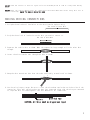
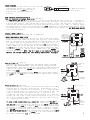
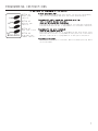
INSTALLATION GUIDE
•
OWNER’S GUIDE
KEYLESS ENTRY • MODELS KE100 / KE150 / 1702
CONTENTS
System Features .......................................
1
System Components .....................................
1
Technical Assistance ..................................
1
Before You Begin ......................................
1
Precautions .........................................
1-2
Making Wiring Connections............................ 2-3
Locating & Making Connections........................ 3-4
Locating & Determining Your Door Lock Types ............ 5
Testing Door Locks ....................................
5
Connecting Door Locks ............................... 5-6
14-Pin Harness Diagram ................................
6
Door Lock Type by Manufacturer ......................... 6
Operating Instructions ................................
6
Programming Instructions .............................. 7
Technical Assistance
All tech personnel are expertly qualified to answer any technical questions.
Technicians are available Monday through Friday from 9:00 a.m. until 8:00 p.m. and Saturday 10:00 a.m. until 4:00 p.m.
Address
288 Canton Avenue • Wintersville, Ohio 43953
Telephone
Phone: 740-264-4710 • 800-878-8007 • Fax: 740-264-7306
SYSTEM FEATURES
Four-Button Remote Control
Remotely lock and unlock your car from a distance.
Starter Immobilizer
You can’t steal what you can’t start. Most insurance companies offer a discount for this feature.
(Optional part #773 required on KE100 only.)
Trunk Release
Remotely opens your trunk. (Optional part #775 required.)
Parking Light Confirmation
Never walk up to a dark car again. Confirms that your vehicle has received a remote signal
and remains on for ten seconds when disarming. (Optional part #775 required.)
Extended Range Antenna
Allows you to operate your system from an extended distance.
Limited Lifetime Warranty
Guarantees life-long protection.
SYSTEM COMPONENTS
Your system includes:
1-Installation & Operation Guide
1-Main Control Module
1-Four Button Remote Transmitter with Slide Protector
1-14-Pin Wire Harness
1-Warranty
2-Bulldog Window Decals
TECHNICAL ASSISTANCE
Should you need help. First check our website at www.bulldogsecurity.com/wires.htm or call our toll-free
Tech Support Hotline Monday through Friday 9AM-8PM and Saturday 10AM-4PM EST at 800-878-8007.
You must give the following information:
•Name
•Telephone Number with Area Code (Fax number if applicable)
•Year, Make, and Model of the vehicle
•The model number of the system you are installing
•The type of assistance you are requesting
If you give the above information you will be called back as soon as possible, usually within 10 minutes.
BEFORE YOU BEGIN
Congratulations, you have purchased one of the most advanced keyless entry systems ever made. Your new
keyless entry is a technological breakthrough utilizing the most advanced, state of the art technology
and components. It is computer controlled and manufactured in the U.S.A. The dependability and variety of
features make Bulldog Security the leader in the industry. Enjoy your new keyless entry for years to come!
Read this manual thoroughly before starting the installation. You must also decide if any options are
desired such as starter immobilizer, trunk release and parking light confirmation. An optional relay may
be needed for some of these options. Please do not skip any steps.
Since there are many different makes and models of vehicles, look at on our website,
www.bulldogsecurity.com/wires.htm.
PRECAUTIONS
This system is designed for vehicles with power door locks only.
This system will add remote keyless entry features to any vehicle with power door locks. This will also
work as a replacement system for the factory installed keyless entry system.
DO NOT use mechanical wiring connections, such as crimp or snap together taps. Follow instructions
on pages 2-3.
DO NOT disconnect the battery if the vehicle has an anti-theft-coded radio or is equipped with an airbag.
Doing so may cause a warning light to be displayed and may require a trip to the dealer to be corrected.
1
DO NOT leave the interior or exterior lights on for an extended period of time as it may cause battery
drain.
DO NOT mount the control module until all connections have been made and tested. Using wire ties or
double sided tape, MOUNT THE MODULE UNDER THE DASH.
MAKING WIRING CONNECTIONS
1. Strip back two inches of insulation on the wire from the keyless entry.
Two Inches of Bare Wire
2. Strip back one inch of insulation on the wire you need to connect to.
One Inch of Bare Wire
3. Separate the vehicle wire as shown. Make the separation large enough to fit the other wire
through.
4. Insert the wire from the unit through the hole as shown.
5. Wrap the wire around one side then the other and finally around itself as shown.
1
2
3
6. Use electrical tape to wrap. Be sure to cover the wire about two inches on either side of the
connection. First pull the wire that you have just connected along side the wire you connected
to, tape and wire tie them together. Use this method for all connections.
Wire Tie
Electrical Tape
CAUTION: All wires must be wrapped and taped.
2
MAKING END TO END CONNECTIONS
FOLLOW THESE INSTRUCTIONS
1. When tying two separate wires together at their ends, strip back 1” of insulation on both
wires and separate the strands of wire as shown below.
2. Twist upper wires together, twist lower wires together as shown.
3. Lay upper twisted pair of wires over right wire as shown. Bring lower twisted pair of wires
up to meet the left wire as shown.
4. Use electrical tape to wrap, be sure to cover about 2 inches on either side of connection.
Secure with wire ties as shown.
Electrical Tape
Wire Tie
Wire Tie
Use this method ONLY when connecting two separate wires end to end.
LOCATING & MAKING CONNECTIONS
Please see the wiring chart on our website, www.bulldogsecurity.com.
CONSTANT POWER (+12V, key in any position including off)
These wire(s) are in your vehicle’s main ignition harness, usually located on the steering column coming
from the ignition switch. Probe each wire with your test light. The correct wire will show +12V when
the ignition switch is in these 4 positions (LOCK-ON-OFF-CRANK). Attach the RED power wire from the
14-pin harness to this wire. NOTE: The RED wire from the 14-pin harness is internally protected. No
fuse is necessary.
3
CHASSIS GROUND
Factory Bolt
Locate an easy to get to bolt or screw
located under the driver’s side of the
dash and attach the BLACK ground wire
Spade Connector
from the 14-pin harness securely as
pictured.
Black Ground Wire
Note: Remove any paint below
the spade connector.
Some vehicles have factory alarms.
FASD (-) (Factory Alarm Shut Down wire) (Optional)
The RED WITH BLACK STRIPE wire provides (-) pulse at the same time the doors unlock. It is provided to
turn the original factory installed alarm off. The facyory disarm wire is usually found in the driver’s
side kick panel and will come from the door lock key cylinder. It will read +12V until the door key is
inserted into the door and turned to the unlock position. At that time it will show a (-) negative output
only while the key is held in the unlock position. NOTE: Some factory disarm wires remain neutral (shows
no voltage) before you turn the key to unlock instead of +12v positive. Connect the RED WITH BLACK STRIPE
wire to this disarm wire.
STARTER IMMOBILIZER (-)
(Optional relay Part #773 required for KE100 only)
INSTALLING STARTER IMMOBILIZER
Locate the starter/crank wire. This wire is also in the main harness.
Locate the wire that shows +12V on your test light only in the cranking
position. This wire will not show +12V in any other position. Cut this
wire in two. Now, try starting the vehicle, it should not start. If
it does not, it is the correct wire. Connect the RED wire from the
starter immobilizer to the “keyside” of the starter/crank wire. Connect
the WHITE wire to the “starter side” of the starter/crank wire. Then
connect the ORANGE wire from the starter immobilizer to the ORANGE wire
on the 14-pin harness. NOTE: You will need to cut factory wiring to
make an end to end connection, see “Making Connections” on page 3.
Connect the
ORANGE from the
14-pin harness
to ORANGE wire
from Part #773.
87a
ORANGE
Diode
WHITE
RED
SWITCH SIDE
TO STARTER
Parking Light (-) (Optional)
(Optional part #775 is needed) Turn the parking lights to the ON
position. (NOT YOUR HEADLAMPS). Probe the wire(s) coming from your
headlamp switch. Find the wire that will show +12V only when the parking
lights are ON. Connect the YELLOW wire from part #775 to this wire.
Connect the BROWN
wire from the 14-pin harness to the WHITE wire on part #775. Connect
the BLACK and the BLUE wires from part #775 to +12V constant fused at
20 amps.
YELLOW
WHITE
87a
Brown(-)
from
module
BLACK
RED
Do not
use, tape
off.
Trunk Release (-) (Optional)
(Optional part #775 is needed) Locate the trunk release wire coming
from the back of the trunk release switch. To determine if your
trunk release is tripped by a (+) positive or a (-) negative (most
trunk release switches are (+) positive). Place one end of your test
light to ground, press the “Trunk” button, if the test light
illuminates, you have a (+) positive trunk release. If it does not,
connect the test light to +12V constant and probe the wire. If the
test light illuminates when the button is pressed, then you have
a (-) negative trunk release.
If your trunk output tests as a positive. Connect the YELLOW wire
from part #775 to the trunk release wire. Connect the WHITE WITH
RED STRIPE wire from the 14-pin harness to the WHITE wire on part
#775. Connect the BLACK wire and the BLUE wire to +12V constant fused
at 20 amps. If your trunk output tests as a (-) negative, connect
the YELLOW wire from part #775 to the trunk release wire. Connect
the WHITE WITH RED STRIPE wire from the 14-pin harness to the WHITE
wire on part #775. Connect the BLACK wire to +12V constant fused
at 5 amps. Connect the BLUE wire to ground.
To parking
light
circuit
BLUE
+12V Fused
at 20 amps
To factory trunk
wire
YELLOW
WHITE
White/Red
(-) from
module
RED
Do not use,
tape off.
87a
BLUE
BLACK
+12V
Constant
fused at
20 amps
4
LOCATING AND DETERMINING YOUR DOOR LOCK TYPE
In most cases, the factory door lock wires will be smaller gauge and located in the driver’s kick panel or
under the driver’s dash.
NOTE: To help determine your door lock type, refer to the Door Lock Types by Manufacturer chart on page 13
or visit our web page at www.bulldogsecurity.com for specific detailed information on a particular vehicle.
If the year of your vehicle is listed as having two or more types of door lock systems, you must test for
all of those types.
TESTING DOOR LOCK TYPE
There are 3 basic system types:
“Type A” Door Lock Test (Most GMs and most Chryslers)
Probe both of your door lock wires going to the door lock switch these wires are usually located in
the driver’s kick panel, attach one end of your test light to a good chassis ground. Using the vehicle’s
door lock controls, activate the lock then the unlock testing both wires one at a time. If the test
light illuminates when you probe the lock and the unlock wires your vehicle has a “Type A” door locking
system. Make sure to mark which wire is lock and unlock.
“Type B” Door Lock Test (Most Imports, some newer Fords)
Probe both door lock wires going to the door lock switch these wires are usually located in the driver’s
kick panel. Attach one end of your test light to +12V using the vehicle’s door lock controls activate
the lock then the unlock testing both wires one at a time. If the test light illuminates when you probe
the lock and the unlock wires your vehicle has a “Type B” door locking system. Make sure to mark which
wire is lock and unlock.
“Type C” Door Lock Test (Most Fords, some Chryslers, GM Trucks)
Using your test light probe both the lock and the unlock wires usually located in the driver’s kick
panel. Attach one end of your test light to ground probing both wires one at a time while locking and
unlocking the doors with the driver’s side switch (usually the master switch). The test light should
illuminate in both switch positions. Now attach one end of your test light to +12V constant, probe both
wires one at a time again. The light should then illuminate again only in reverse order. This tells you
that you have a “Type C” reversing polarity system. Make sure to mark which wire is lock and unlock.
CONNECTING DOOR LOCKS
“Type A” (+) Positive
“Type B” (-) Negative
RED
Ground
BLUE/BLACK Unlock
BROWN/BLACK Not Used
PURPLE
UNLOCK
FUSE
+12V Constant
GREEN/BLACK Lock
LOCK
WHITE/BLACK Not Used
NOTE: Connect the PURPLE WITH BLACK STRIPE
wire from the fuse to +12V constant
power.
+12V Constant
BLACK
KEYLESS MODULE
KEYLESS MODULE
BLACK
PURPLE/BLACK
RED
+12V Constant
Ground
BLUE/BLACK Unlock
BROWN/BLACK Not Used
PURPLE
PURPLE/BLACK
UNLOCK
FUSE
Ground
GREEN/BLACK Lock
LOCK
WHITE/BLACK Not Used
Yellow Antenna
Keep as straight
as possible, tape
the end to hold
straight.
NOTE: Connect the PURPLE WITH BLACK STRIPE
wire from the fuse to ground.
Yellow Antenna
Keep as straight
as possible, tape
the end to hold
straight.
5
14-PIN HARNESS DIAGRAM
“Type C” Reverse Polarity
RED
+12V Constant
BLACK
Ground
POWER
DOOR
LOCK
MOTOR
KEYLESS MODULE
BLUE/BLACK Unlock
BROWN/BLACK Unlock
PURPLE
PURPLE/BLACK
FUSE
+12V
Constant
(+)12V Constant
BLACK
Ground
BROWN
(-)Parking Light Output
WHITE/RED
(-)Trunk Pop
ORANGE
(-)Starter Kill
RED/BLACK
(-)FASD
not used
GREEN/BLACK Lock
WHITE/BLACK Lock
LOCK
NOTE: Connect the PURPLE WITH BLACK
STRIPE wire from the fuse
to +12V constant power.
RED
Yellow Antenna
Keep as straight
as possible, tape
the end to hold
straight.
WHITE/BLACK
Lock (87A)
GREEN/BLACK
Lock (30)
BROWN/BLACK
Unlock (87A)
BLUE/BLACK
Unlock (30)
YELLOW
Antenna
PURPLE
PURPLE/BLACK
FUSE
PURPLE/BLACK
UNLOCK
NOTE: You will need to cut factory wiring to
make an end to end connection, see “Making
Connections” on page 3.
DOOR LOCK TYPES BY MANUFACTURER
DOOR LOCK TYPES BY MANUFACTURER
“Type A”
Most Buicks 85-96
Most Cadillacs 85-96
Most Chevrolets 85-94
4 door SUVs, vans 85-2000
Most Oldsmobiles 85-95
Most Pontiacs 85-95
Some Fords 96-2000
Some Mercurys 96-2000
Some Lincolns 96-2000
Most
Most
Most
Some
Chryslers 96-2000
Dodges 96-2000
Plymouths 96-2000
Volkswagens 92-2000
“Type B”
Some Buicks 97-2000
Some Cadillacs 96-2000
Some Oldsmobiles 96-2000
Some Pontiacs 96-2000
Some
Some
Some
Most
Most
Most
Most
Some
Some
Fords 96-2000
Mercurys 96-2000
Lincolns 96-2000
Hondas 85-2000
Toyotas 85-2000
Nissans 85-2000
Mazdas 85-2000
Subarus 85-2000
Volkswagens 92-2000
“Type C”
Some Chevrolets 96-2000
All Trucks 2 door 89-2000 SUVs
2 door 89-2000
Most Fords 88-96 All Trucks 85-2000
Most Mercurys 88-96
Most Lincolns 88-96
Some Chryslers 85-95
Some Dodges 85-95
Some Plymouths 85-95
NOTE: If your vehicle requires a double pulse to lock or unlock due to factory security systems, please see
programming instructions on page 7. (Double pulse door locks are used in some Japanese imports and some newer
domestic vehicles.
OPERATING INSTRUCTIONS
1. Lock
Press and release button #1 (lock) the doors will lock. Starter immobilizer will engage.
2. Unlock
Press and release button #2 (unlock) the doors will unlock. Starter immobilizer will be disengaged.
3. Trunk
Press and release button #3 (trunk) the trunk will release. NOTE: This will send a negative 250ma output as
long as button #3 is pressed.
4. Program
This is your programming button.
6
PROGRAMMING INSTRUCTIONS
In most cases the programming will NOT be used.
Lock
Unlock
Trunk
Program
BULLDOG
BUTTON #1
Locks your
vehicle.
BUTTON #2
Unlocks your
vehicle.
BUTTON #3
Pops your trunk
BUTTON #4
Programs your
remote control.
To enter programming mode
Press button #4 for 10 seconds then release. You are now in programming
mode. To exit programming mode press and release button #4 again.
Programming 0.7 and 3.5 second door lock/unlock pulse time
(This is used for European cars only)
(Used only with vacuum door lock system)
Press button #1 once the unit is programmed for 3.5 second door lock/unlock.
Press button #1 twice the unit is programmed for 0.7 second door lock/unlock.
Programming for dual pulse lock/unlock
(Used on some Japanese vehicles)
Press button #2 once, the unit is programmed for dual pulse unlock. Press
button #2 twice, the unit is programmed for dual pulse lock. Press button
#2 three, times the unit is programmed for no dual pulse lock/unlock.
Programming a new remote
Press and hold button #1 for 10 seconds. Within 10 seconds press any button
on the new remote.
7