1
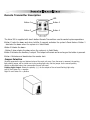
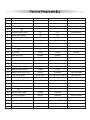
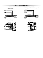
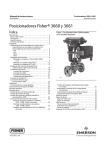
ASTRA 300RS
REMOTE START WITH KEYLESS ENTRY
AUTOMATIC TRANSMISSION ONLY
PRODUCT MANUAL
Remote Transmitters
Remote Transmitter Description
LED
Button 1
Button 2
Button 3
Button 4
The Astra 300 is supplied with two 4-button Remote Transmitters used to control system operations.
Button 1 Locks the doors and when held for 2 seconds, activates the system’s Panic feature. Button 1
also locks the doors when the system is in Valet Mode.
Button 2 Unlocks the doors.
. Button 2 also unlocks the doors when the system is in Valet Mode.
Button 3 Activates the Auxiliary 1 output. This output will remain on for as long as the button is pressed.
Button 4 Activates and deactivates the remote start.
Jumper Selection
Carefully separate the top and bottom halves of the main unit case. Once the cover is removed, the parking
light polarity jumper will be visible next to the parking light relay. Set the jumper for the correct polarity
output as described below, then reassemble the main unit case.
Parking Light Output. Selects the polarity (+/-) for the output of the on-board Parking Light relay.
Left Pin and Center Pin = negative
Right Pin and Center Pin = positive
System Operation 300RS
Adding/Replacing One-Way Transmitters
To replace lost or stolen transmitters or to add additional transmitters into the system, have all desired
transmitters ready and follow the steps below.
Note: Up to 4 transmitters can be programmed to operate the system. To erase any previously stored
transmitter codes, be sure to program all 4 transmitter memory locations.
To program the transmitter(s):
1. Turn on the ignition key On, Off, On, Off, and back On.
· The Horn will flash 3 times.
2. Press and hold the Valet switch for 5 seconds.
· The Horn will flash 5 times.
· The
3.
· The
4.
5.
LED will illuminate.
Press Button 1 on the first transmitter.
horn will flash once.
Repeat steps 3 for each transmitter (up to 4).
Turn off the ignition key.
Battery Replacement
Your Remote Transmitter uses a 12 volt alkaline battery (type 23A), which will require replacement in
time. Depending on the amount of use, the battery may last up to six months or more before it
needs replacement.
When the battery needs replacing, the system’s operating range will decrease or the transmitter LED
may not be as bright.
In order to change the battery, first remove 2 screws from the back of the transmitter and separate
the top and bottom halves of the case.
While replacing the battery make sure that the positive and negative terminals are positioned correctly, then carefully reassemble the transmitter case.
Panic Mode
In the event of an emergency the transmitter’s remote Panic feature can be used to instantly trigger
the Horn.
To activate the Panic Mode:
1. Press and hold Button 1 for 3 seconds.
· The horn will sound.
· The parking lights will flash.
· The doors will unlock* allowing access to the vehicle.
2. Press Button 2 to stop Panic Mode.
* If the ignition is on when the Panic feature is activated, the doors will lock for personal safety.
If not deactivated using Button 2, the Panic Mode will automatically exit after 30 seconds and the system
will be restored to its previous Lock/Unlock state.
Remote Starting
System Operation 300RS
To Remote Start the System:
1. Be sure the system is not in Valet Mode.
2. Press Button 1 on the remote for two seconds.
· The parking lights will flash 4 times and turn on.
· The Horn will chirp 4 times when starter confirmation chirps is enabled.
· The engine will start and run for the duration of its programmed Run Time.*
· The heater or air conditioner will turn on (if turned on prior to exiting the vehicle).
*If the engine fails to start on the first attempt, it will repeat the starting procedure 2 more times. If the vehicle
fails to start after a total of 3 times the parking lights will flash 4 times and the doors will lock (if installed).
Turn on the ignition and press the brake pedal to disengage the remote start feature and drive the vehicle
Remote Shut Down
When the the Remote Start feature is active, any of the following actions will shutdown the engine:
1. Pressing and releasing Button 1 within 1 second.
· After the engine shuts down the doors will lock (if installed).
2. Pressing the Brake Pedal.
3. Opening the Hood.
4. Remote Start Time-Out (completion of the timed run cycle).
Remote Unlocking
To unLock the doors:
1. Press and hold button 1 on the remote for 3 seconds. (this feature works only when engine is running).
· The doors will unlock.
· The parking lights will flash twice.
Auxiliary Function Outputs
The ASTRA 300RS are equipped with 1 Auxiliary Channel Output allowing the convenience features of the
system to be further expanded. This output can be programmed for pulsed, timed, or latched operation, and
used to add a number of optional features such as: power trunk release, power window activation, power
sunroof control, auxiliary lighting, audio/video system control, and more.
The Pulsed operation setting allows an output to activate as long as the button is held.
The Timed operation setting allows an output to activate when the transmitter button is pressed, and
remain activated for 10 seconds or until the transmitter button is pressed again.
The Latched operation setting allows an output to activate when the transmitter button is pressed, and
remain activated until the transmitter button is pressed again.
Emergency Valet Switch
If the transmitter becomes lost or inoperable, the Doors can still be unlocked using the following procedure. Before
beginning this procedure be sure to have the ignition key ready and know the location of the valet switch.
To Emergency Valet the system:
1. Unlock the door using the key.
2. Enter the vehicle.
3. Turn ignition key on.
4. Press and hold the valete switch until LED turns off.
· The system will deactivate the starter intrruptoutput.
5. The vehicle will now be able to start.
Valet Mode
The Valet Mode temporarily disables remote start system so the vehicle may be operated by a mechanic.
To activate or deactivate the Valet Mode:
1. Turn on the ignition.
2. Press and hold the valet switch for 5 seconds.
· The horn will chirp once and the LED light will stay ON to confirm the Valet Mode is on.
· The horn will chirp twice and the LED light will turn OFF to confirm the Valet Mode is off.
3. Turn off the ignition.
While in Valet Mode the remote transmitters will continue to lock and unlock the doors, and operate the optional auxiliary functions.
System Installation
1. Thoroughly read and become familiar with the installation instructions before beginning the installation.
2. Review system contents:
Main Unit
Two 4-Button Remote Transmitters
Harnesses
• 6-Wire starter harness
• 3-Pin Power harness
• 8-Pin main harness
• 3-Pin door lock harness
• LED, Valet Switch and antenna Harness
3. Verify vehicle is equipped with electronic fuel injection, and starts/idles normally before installation.
4. Determine if vehicle is equipped with a factory theft deterrent system and obtain proper bypass module if required.
5. Find a location to mount the hood pin switch that will not interfere with the opening of the hood, and is not in a
position that can accumulate water. The hood pin is a safety device that must be installed to avoid remote starting
during engine servicing.
6. Verify with the owner, the mounting locations for all visible components, including the LED and Valet switch.
7. Verify with the owner, the optional features of the ASTRA/300RS and the features that must be programmed during
installation.
8. Inspect and perform a function test of all vehicle systems before and after the installation.
9. Always use a Volt / Ohm meter for testing vehicle circuits. Never use a test light.
10. Always look before drilling any holes or mounting self-tapping screws. Be sure fuel lines and exterior wiring looms
are clear as they are often close to the chassis and difficult to see.
11. Protect all wires running from the engine compartment to the interior of the vehicle by covering with electrical
tape and split loom tubing. Be sure to use a grommet when routing wires through the firewall.
12. Properly fuse any additional accessories such as window modules, door lock actuators, etc., making sure to power
them separate from the alarm module. This will ensure the functionality of the security system in the event of an
accessory failure.
Mounting the Control Unit
The control unit must only be mounted in the interior of the vehicle. Do not mount the main unit in the engine compartment. Choose a mounting location that will not be easily accessible to a thief, and will not interfere with the operation of any vehicle components such as foot pedals, steering column, air vents, seat rails, etc. Do not mount the
control unit until after setting the internal jumpers and performing a complete operation check of the system. After
installation is complete and performance verified, the control unit can be easily mounted using wire ties through the
mounting tabs on the bottom of the unit.
6-Wire Starter Harness
System Wiring
Pin 1 RED - A: Main Power Input A (+). Connect to the battery or constant power wire at the ignition switch with a
minimum 30 Amp supply. Remove the fuse until the installation is complete and all wiring is checked.
Pin 2 RED - B: Main Power Input B (+). Connect to the battery or constant power wire at the ignition switch with a
minimum 30 Amp supply.
Pin 3 BROWN: Second Ignition Output (+). The Brown wire provides +12V for a second ignition wire. This wire may
instead be programmed for use as a second accessory or second starter wire.
Pin 4 ORANGE: Accessory Output (+). Connect to the accessory wire coming from the ignition switch that supplies
power to the heater/air-conditioner. Some cars may have multiple accessory wires.
Pin 5 YELLOW: Ignition Output (+). Connect to the main ignition wire that provides +12V when the ignition is on
and while cranking the starter.
Pin 6 VIOLET: Starter Output (+). Connect to the the vehicle’s starter wire.
Note: if connecting at the ignition switch it is highly recommended to use separate power wires for each Red wire,
each with a minimum 30A supply. Remove the fuse until the installation is completed and all wiring is checked.
3-Pin Power Harness
Pin 1 RED WIRE: Module Power Input (+). Connect to a constant source of +12V.
Pin 2 WHITE: Parking Light Output (+/-) relay. Connect the White wire to the circuit that shows +12V or ground
only when the parking lights are on and set the internal parking light relay jumper to the proper polarity. For parking light circuits exceeding 10 amps, a relay is required. For vehicle’s with independent left and right parking light
circuits, diodes must be installed to keep the circuits separate.
NOTE: Do not connect the WHITE wire to the vehicle’s headlight circuit.
Pin 3 BLACK: Ground Input (-), The Black wire must connect to a solid chassis ground. Clean away any paint or dirt
to insure the best possible ground.
8-Pin Main Harness
Pin 1 WHITE/VIOLET: Factory Disarm Output (-) 500 mA. The Violet/white wire provides a ground output on disarming and before remote starting to disarm a factory security system. Connect to the wire that requires a ground
pulse to disarm the factory security system.
Pin 2 BLUE/ORANGE: Ground When Running Output (-) 500 mA. Connect to an optional factory security bypass
module if required.
Pin 3 BROWN/WHITE: Horn Output (-) 500 mA. Connect to a relay to activate the vehicle’s horn when the alarm is
triggered.
Pin 4 GRAY: Auxiliary 1 Output (-) 500 mA. Connect to a relay for an optional feature such as trunk release, etc.
This output may be programmed for momentary, timed, or latched operation.
Pin 5 WHITE/BLACK: Hood Pin Input (-). Connect the to the hood pin switch. The switch must provide a ground
output when switch is opened.
Pin 6 GREEN/WHITE: Brake Input (+). Connect to the wire that shows +12V when pressing the brake. The
Green/white wire is a safety shutdown wire that must be connected.
Pin 7 BLACK/GRAY: Tach Input. Connect to the vehicle’s tach wire or a fuel injector wire if the tachless mode does
not provide satisfactory operation.
Pin 8 ORANGE: Programmable Starter Disable Output (-) 500 mA. The Orange wire provides a ground output while
locked to disable the starter on the vehicle/ Factory Rearm Output.
5-Pin White Connector: Two Way Receiver Connector.
3-Pin White Door Lock Connector: Door lock port.
• BLUE WIRE - negative unlock output (-) 500mA.
•GREEN WIRE- negative lock output (-) 500mA.
System Programming
System Programming
The system programming is compatible with both the LCD transmitter or the standard AM transmitter.
Enter System Programming:
1. Turn on ignition.
2. Within 5 seconds, press the valet switch 5 times.
· The horn will provide three chirps, indicating that you have entered Programming.
3. Press the valet switch the number times equal to the System Parameter you want to change.
· The horn will chirp each time the valet switch is pressed.
4. Within 5 seconds, press the transmitter button corresponding to the desired operating mode for
that System Parameter.
· The horn will chirp to indicate the setting.
1 chirp = Button 1
2 chirps = Button 2
3 chirps = Button 3
5. When you are finished, turn off the ignition to save the changes.
Default Reset
Following this procedure will set all System Programming Parameters to factory default settings.
1. Enter System Programming.
2. Press Transmitter Button 3.
· The horn will chirp 6 times indicating that the reset signal was received.
· All System Programming parameters are now set to factory default settings.
· The Valet Mode is off.
3. Turn off ignition.
Programmable System Options
The following is a description of the programming options of the system. Some of the program branches control more
than one option, and may require accessing a particular branch number twice in order to program all desired features.
3. Lock/Unlock Chirps. Selects between normal and silent operation.
5. Extended Parking Lights. When Enabled, upon Disarming Parking lights will turn On for 30 seconds or until the
Dome light turns Off
Reset Mobilink (Galaxy Mobile) module.
6. Ignition Door Locking / Valet Code Set. This dual program branch selects Ignition Door Locking, and programs the
optional Emergency Valet Code. Ignition Door Locking. Selects whether or not the system will automatically lock the
doors 5 seconds after the ignition key is turned on. Valet Code Set. Changes the Emergency Valet Code for a higher
level of security.
7. Ignition Door Unlocking. Selects whether or not the system automatically unlocks the doors when the ignition is
turned off.
8. Door Unlock Pulse. Selects between one pulse or two pulse operation for the door unlock output. Many new import
vehicles’ factory door locking systems require two pulses on the proper wire to unlock the doors. These systems can
be interfaced directly without the use of relays or any additional circuitry by programming the system for double unlock pulse. also programs to pulse the ignition before unlock
9. Door Lock Pulse Length. Selects between a 1-second, 3-second or 0.1 second output for door locking and unlocking.
Program to 3 seconds for vehicles equipped with vacuum door locking systems. 0.1 seconds for vehicles that roll
windows up or down when lock/unlock output is at 1 second.
System Programming
12. Auxiliary 1 Mode. Selects from momentary, 10 second timed, or latched operation for Auxiliary 1. Momentary operation provides an output for as long as the transmitter button is pressed. Timed operation provides an output that
turns on for 10 seconds each time the transmitter button is pressed. If the button is pressed again during the 30
seconds, the output will turn off. Latched operation provides an output that turns on when the transmitter button is
pressed and remains on until the transmitter button is pressed again.
13. Unlock with Auxiliary 1. When selected, activating the Auxiliary 1 output (usually used to open the trunk) will
disarm the alarm.
14. Starter Confirmation Chirps. When Enabled, horn will chirp to confirm Starter Active state. Enable Auxiliary Start
Activation. Enable to use the axillary start feature if used in keless entry mode.
15. Start in Valet Mode. Selects whether or not the vehicle can remote start while in the valet mode.
16. Lock After Start. When selected, the doors will automatically lock after remote starting.
17. Lock After Shutdown. When selected, the doors will automatically lock after remote shutdown.
18. Engine Run Time. Selects between 15 or 25 minutes for the remote start run cycle.
19. Automatic Start Mode. Selects between every two hours or every hours for the automatic engine starting feature.
20. Tachless Sense Crank Time. Selecting engine crank time automatically selects the tachless mode and one of three
crank times. If the normal engine crank time is too short increase the time by selecting one of the two additional
extended crank time options.
Normal - 0.8Sec.
Extended - 1.0Sec.
Super Extended - 1.4Sec.
Tachless Mode. Determines the engine status using an advanced software routine, without requiring connection to
the vehicle’s tachometer. Tachless operation may not be compatible with some vehicles or in severe temperatures,
in which case the tach wire must be connected.
21. Remote Start Program. This dual program branch sets the engine mode for Gas or Diesel, and learns the vehicle’s
RPM threshold. Learning the RPM threshold automatically selects the RPM monitor mode. For installation into a diesel
equipped vehicle, first set the engine type to diesel before learning RPM. Tach Monitor Mode. Monitors the vehicle’s
tach wire (or a fuel injection wire) in real-time to determine engine status and adjust starter crank time automatically.
If programmed for Tach Monitor, the vehicle’s tach signal will have to be learned before initial operation (see below).
RPM Learn. Start the engine, enter Branch 21 and press Button 1 to learn the vehicle’s tach signal. The horn will
chirp and the LED will flash once to confirm learning of the tach signal and entering Tach Monitor Mode. The horn
will chirp four times and the LED will flash four times if the tach signal was not learned, engine sense mode will not
be changed. Gas Engine. Sets the engine type for Gasoline. Diesel Engine. Sets the engine type for Diesel and monitors the glow plug input to make sure the glow plugs are warm before cranking the starter. If the glow plug wire is
not connected, the built-in timer waits 15 seconds before automatically cranking the starter.
22. Ignition 2 Relay Program. Selects one of three operating modes for the Ignition 2 relay output: Ignition 2, Accessory
2, or Starter 2.
26. Data Bus Input Trigger. When enabled, all available trigger from the Data Bus Module will be monitored.
( door,hood,brake and all other triggers will not be nessecery to hard wire).
27. Horn Chirp Duration. Selects between Normal,(default) Extended, and super extended horn On time During chirping
of the horn.
28. Starter Disable Output Mode. Select between Starter Disable output, Factory Rearm output and Second Auxiliary
output, on the orange wire.
29. Selects between Astra 1000RS and Astra 4000RS - doesn’t apply to Astra 300RS.
30. When enabled doors unlock before start.
31. Data Port Interface Mode: Selects between iDatalink and Fortin module communications.
System Programming
Brunch
Feature
2
NA
1
NA
Button 1
Button 2
Button 3
Silent
Horn Chirps ON
Reset Mobilink
3
Lock/Unlock Chirps
5
Extended Parking Lights
On
Off
7
Ignition Door Unlocking
On
Off
4
6
8
9
10
11
NA
Ignition Door Locking
Door Unlock Pulse
Door Lock Pulse Length
N.A
N.A
12
Aux 1 Mode
14
Starter Confirmation Chirps
13
15
16
17
18
19
20
21
22
23
Unlock with Aux 1
Lock After Start
Lock After Shut Down
Engine Run Time
Automatic Start Interval
Tachless Sense Crank Time
Engine Sense Mode
Remote Start Program
Output Ignition 2 Program
N.A
24
N.A
26
Data Bus Input Trigger
28
Starter Disable Output Mode
25
27
29
30
31
N.A
Horn Chirp Duration
System Mode (Astra 1000/4000)
Unlock Before Start
Data Port Interface Mode
On
Off
Single
Double
Pulse Ignition before Unlock
Pulsed
Timed
Latched
1 Sec
3 Sec
Disabled
Enabled
On
Off
Disabled
On
15 Min
2 Hour
Normal
Enabled
Off
25 Min
1 Hour
Extended
Super Extended
Gas Engine
Diesel Engine
Smart Start
Smart Start Monitor Disabled
Ignition 2 Ouput
Accessory 2 Output
Enabled
Disabled
RPM Mode/RPM Learn
Normal
Extended
Starter Disable Output
Factory Rearm Output
Disabled
Enabled
Astra 1000RS
iDataLink
0.1 Sec
Astra 4000RS
Fortin
Data Bus RPM
Starter 2 Output
Super Extended
Aux 2
Door Lock Diagrams
Negative Trigger
Reverse Polarity
Positive Trigger/ additional 2 relays reqiured
Adding Actuators
Wiring Diagram
Starter Harness
Power
Astra 300RS
Main Harnes
Door Lock
White Blue
Red
Brown - Ignition-2 (+)
Yellow - Ignition -1 (+)
Orange - Accessory (+)
Violet - Starter Out (+)
Red - Battery 1 (+)
Red - Battery 2 (+)
Red - +12v In (+)
White - Parking Light Out (+/-)
Black - Ground in (-)
White/Violet - Factroy Disarm Out (-)
Blue/Orange - Ground When Running Out (-)
Brown/White - Horn Out (-)
Gray - Trunk - Release Out (-)
White/Black - Hood Trigger In (-)
Green/White - Brake Light In (+)
Black/Gray - RPM In
Orange - Starter Disable/Factory Rearm/Ign-3 (-)
Blue - Unlock (-)
Green - Lock (-)
White
Antenna/Mobilink
LED light
Valet Switch
Bypass Module Port
SKYTEK ELECTRONICS SECURITY
CAR SECURITY SYSTEM