1
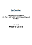
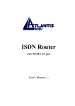
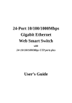
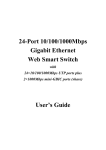
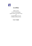
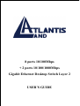
8 ports 10/100Mbps
+ 2 ports 10/100/1000Mbps
Gigabit Ethernet Desktop Switch Layer 2
USER’S GUIDE
The Atlantis Land logo is a registered trademark of Atlants Land SpA.
All other names mentioned mat be trademarks or registered
trademarks of their respective owners. Subject to change without
notice. No liability for technical errors and/or omissions.
FCC Warning
This equipment has been tested and found to comply with the limits
for a Class B digital device, pursuant to Part 15 of the FCC Rules.
These limits are designed to provide reasonable protection against
harmful interference when the equipment is operated in a commercial
environment. This equipment generates, uses, and can radiate radio
frequency energy and, if not installed and used in accordance with this
user’s guide, may cause harmful interference to radio
communications. Operation of this equipment in a residential area is
likely to cause harmful interference in which case the user will be
required to correct the interference at his own expense.
CE Mark Warning
This is a Class B product. In a domestic environment, this product
may cause radio interference in which case the user may be required
to take adequate measures.
A02-F8-2C/M2 (september 2002)
TABLE
OF
C ONTENTS
ABOUT THIS GUIDE ....................................................... 1
TERMS .............................................................................................. 1
OVERVIEW OF THIS USER’S GUIDE ................................................... 1
INTRODUCTION ................................................................. 2
GIGABIT ETHERNET TECHNOLOGY ................................................... 2
FAST ETHERNET TECHNOLOGY......................................................... 3
SWITCHING TECHNOLOGY ................................................................ 4
FEATURES ......................................................................................... 5
Ports ............................................................................................ 5
Performance features ............................................................... 5
UNPACKING AND SETUP .......................................... 6
UNPACKING ...................................................................................... 6
SETUP ............................................................................................... 6
DESKTOP OR SHELF INSTALLATION .................................................. 7
RACK INSTALLATION (OPTIONAL)..................................................... 8
CONNECTING NETWORK CABLE ....................................................... 9
POWER ON ........................................................................................ 9
IDENTIFYING EXTERNAL COMPONENTS
........................................................................................................... 10
FRONT PANEL ................................................................................. 10
REAR PANEL ................................................................................... 11
LED INDICATORS ........................................................................... 11
TECHNICAL SPECIFICATIONS ......................... 13
i
A BOUT T HIS G UIDE
This user’s guide tells you how to install your 10-port
10/100/1000Mbps Gigabit Ethernet Switch, how to connect it to your
network.
Terms
For simplicity, this documentation uses the terms “Switch” (first letter
upper case) to refer to the 10-port 10/100/1000Mbps Gigabit Ethernet
Switch, and “switch” (first letter lower case) to refer to all Ethernet
switches, including the 10-port 10/100/1000Mbps Gigabit Ethernet
Switch.
Overview of this User’s Guide
♦ Introduction. Describes the Switch and its features.
♦ Unpacking and Setup. Helps you get started with the basic
installation of the Switch.
♦ Identifying External Components. Describes the front panel,
rear panel, and LED indicators of the Switch.
♦ Connecting the Switch. Tells how you can connect the Switch
to your Ethernet network.
♦ Technical Specifications. Lists the technical specifications of
the 10-port 10/100/1000Mbps Gigabit Ethernet Switch.
1
I NTRODUCTION
This section describes the features of the 10-port 10/100/1000Mbps
Gigabit Ethernet Switch, as well as giving some background
information about Gigabit Ethernet, Fast Ethernet and Switching
technology.
Gigabit Ethernet Technology
Gigabit Ethernet is an extension of IEEE 802.3 Ethernet utilizing the
same packet structure, format, and support for CSMA/CD protocol,
full duplex, flow control, and management objects, but with a tenfold
increase in theoretical throughput over 100-Mbps Fast Ethernet and a
hundredfold increase over 10-Mbps Ethernet. Since it is compatible
with all 10-Mbps and 100-Mbps Ethernet environments, Gigabit
Ethernet provides a straightforward upgrade without wasting a
company’s existing investment in hardware, software, and trained
personnel.
The increased speed and extra bandwidth offered by Gigabit Ethernet
is essential to coping with the network bottlenecks that frequently
develop as computers and their busses get faster and more users use
applications that generate more traffic. Upgrading key components,
such as your backbone and servers to Gigabit Ethernet can greatly
improve network response times as well as significantly speed up the
traffic between your subnets.
Gigabit Ethernet enables fast optical fiber connections to support
video conferencing, complex imaging, and similar data-intensive
applications. Likewise, since data transfers occur 10 times faster than
Fast Ethernet, servers outfitted with Gigabit Ethernet NIC’s are able
2
to perform 10 times the number of operations in the same amount of
time.
In addition, the phenomenal bandwidth delivered by Gigabit Ethernet
is the most cost-effective method to take advantage of today and
tomorrow’s rapidly improving switching and routing internetworking
technologies. And with expected advances in the coming years in
silicon technology and digital signal processing that will enable
Gigabit Ethernet to eventually operate over unshielded twisted-pair
(UTP) cabling, outfitting your network with a powerful 1000-Mbpscapable backbone/server connection creates a flexible foundation for
the next generation of network technology products.
Fast Ethernet Technology
The growing importance of LANs and the increasing complexity of
desktop computing applications are fueling the need for high
performance networks. A number of high-speed LAN technologies
have been proposed to provide greater bandwidth and improve
client/server response times. Among them, 100BASE-T (Fast
Ethernet) provides a non-disruptive, smooth evolution from the
current 10BASE-T technology. The non-disruptive and smooth
evolution nature, and the dominating potential market base, virtually
guarantee cost effective and high performance Fast Ethernet solutions
in the years to come.
100Mbps Fast Ethernet is a new standard specified by the IEEE 802.3
LAN committee. It is an extension of the 10Mbps Ethernet standard
with the ability to transmit and receive data at 100Mbps, while
maintaining the CSMA/CD Ethernet protocol. Since the 100Mbps
Fast Ethernet is compatible with all other 10Mbps Ethernet
3
environments, it provides a straightforward upgrade and takes
advantage of the existing investment in hardware, software, and
personnel training.
Switching Technology
Another key development pushing the limits of Ethernet technology is
in the field of switching technology. A switch bridges Ethernet
packets at the MAC address level of the Ethernet protocol transmitting
among connected Ethernet or fast Ethernet LAN segments.
Switching is a cost-effective way of increasing the total network
capacity available to users on a local area network. A switch increases
capacity and decreases network loading by making it possible for a
local area network to be divided into different segments which don’t
compete with each other for network transmission capacity, giving a
decreased load on each.
The switch acts as a high-speed selective bridge between the
individual segments. Traffic that needs to go from one segment to
another is automatically forwarded by the switch, without interfering
with any other segments. This allows the total network capacity to be
multiplied, while still maintaining the same network cabling and
adapter cards.
Switching LAN technology is a marked improvement over the
previous generation of network bridges, which were characterized by
higher latencies. Routers have also been used to segment local area
networks, but the cost of a router and the setup and maintenance
required make routers relatively impractical. Today’s switches are an
ideal solution to most kinds of local area network congestion
problems.
4
Features
The 10-port 10/100/1000Mbps Gigabit Ethernet Switch was designed
for easy installation and high performance in an environment where
traffic on the network and the number of users increase continuously.
Switch features include:
Ports
♦ Two 10/100/1000Mbps Gigabit Ethernet port (port 9 ~ 10).
♦ Eight 10/100Mbps Fast Ethernet ports (port 1 ~ 8).
Performance features
♦ Store and forward switching scheme capability to support rate
adaptation and protocol conversion.
♦ Full duplex to allow two communicating stations to transmit
and receive at the same time.
♦ Wire-speed data forwarding rate for each port.
♦ Wire-speed data filtering rate for each port.
♦ 6K active MAC address entry table per device with automatic
learning and aging.
♦ 256K bits packet buffer per device.
♦ Supports broadcast storm rate filtering.
5
U NPACKING AND S ETUP
This chapter provides unpacking and setup information for the
Switch.
Unpacking
Open the shipping carton of the Switch and carefully unpack its
contents. The carton should contain the following items:
♦ One 10-port 10/100/1000Mbps Gigabit Ethernet Switch
♦ Four rubber feet with adhesive backing
♦ One AC power cord
♦ This User’s Guide (on CD-Rom)
If any item is found missing or damaged, please contact your local
reseller for replacement.
Setup
The setup of the Switch can be performed using the following steps:
♦ The surface must support at least 5 kg.
♦ The power outlet should be within 1.82 meters (6 feet) of the
device.
♦ Visually inspect the power cord and see that it is secured fully
to the AC power connector.
6
♦ Make sure that there is proper heat dissipation from and
adequate ventilation around the Switch. Do not place heavy
objects on the Switch.
Desktop or Shelf Installation
When installing the Switch on a desktop or shelf, the rubber feet
included with the device must be first attached. Attach these
cushioning feet on the bottom at each corner of the device. Allow
enough ventilation space between the device and the objects around it.
Figure 2-1. Gigabit Ethernet Switch installed on a Desktop or Shelf
7
Rack Installation (optional)
The 10-port 10/100/1000Mbps Gigabit Ethernet Switch can be
mounted in an EIA standard size, 19-inch rack, which can be placed
in a wiring closet with other equipment. To install, attach the
mounting brackets on the switch’s front panel (one on each side) and
secure them with the screws provided.
Figure 2- 2A. Attaching the mounting brackets to the Switch
Then, use the screws provided with the equipment rack to mount the
Switch in the rack.
Figure 2-2B. Installing the Switch in an equipment rack
8
Connecting Network Cable
The Gigabit Ethernet Switch supports two 10/100/1000Mbps Gigabit
Ethernet ports and eight 10/100Mbps Fast Ethernet ports. Port 1 to
port 8 supports 10Mbps Ethernet or 100Mbps Fast Ethernet. Port 9 to
port 10 are Gigabit Ethernet port, it supports 10Mbps, 100Mbps and
1000Mbps. And these ports runs both half duplex and full duplex
while it’s running in 10Mbps, 100Mbps or 1000Mbps.
These ports are Auto-MDI type port, these ports can auto transform to
MDI-II or MDI-X type, so you can just make an easy connection that
without worrying if you are using a standard or crossover cable.
Power on
The 10-port 10/100/1000Mbps Gigabit Ethernet Switch can be used
with AC power sources 100 - 240 VAC, 50 - 60 Hz. The Switch’s
power supply will adjust to the local power source automatically and
may be turned on without having any or all LAN segment cables
connected.
9
I DENTIFYING E XTERNAL C OMPONENTS
This chapter describes the front panel, rear panel and LED indicators
of the Switch
Front Panel
The front panel of the Switch consists of 8 10/100Mbps Ethernet
ports, 2 10/100/1000Mbps Gigabit Ethernet port, and LED indicators.
Figure 3-1. Front panel view of the 10-port 10/100Mbps Gigabit
Ethernet Switch
♦ Two 10/100/1000Mbps Gigabit Ethernet ports (port 9 ~10).
♦ Eight 10/100Mbps Fast Ethernet ports (port 1 ~ 8).
♦ Comprehensive LED indicators that display the conditions of
the Switch and status of the network. A description of these
LED indicators follows (see LED Indicators).
10
Rear Panel
The rear panel of the Switch consists of an AC power connector. The
following shows the rear panel of the Switch.
Figure 3-2. Rear panel view of the 10-port 10/100/1000Mbps Gigabit
Ethernet Switch
♦ AC Power Connector This is a three-pronged connector that
supports the power cord. Plug in the female connector of the
provided power cord into this connector, and the male into a
power outlet. Supported input voltages range from 100 ~ 240
VAC at 50 ~ 60 Hz.
LED Indicators
The LED indicators of the Switch include Power, SPEED, LINK/ACT
and FDX/COL. The following shows the LED indicators for the
Switch along with an explanation of each indicator.
11
Figure 3-4. The 10-port 10/100/1000Mbps Gigabit Ethernet Switch
LED indicators
♦ POWER After turning on the power, the Power indicator on
the front panel should light to indicate the Switch is receiving
power.
♦ SPEED The indicator lights amber when the port is connected
to 1000Mbps Gigabit Ethernet station, and the indicator lights
green when the port is connected to 100Mbps Fast Ethernet
station. Otherwise, this indicator remains off when the port is
connected to a 10Mbps Ethernet station.
♦ LINK/ACT This indicator light green when this port is
connected to a station successful, if this indicator blinking
green means this port will be transmitting or received data on
the network.
♦ FDX/COL This LED indicator light green when a respective
port is in full duplex (FDX) mode. Otherwise, it is blinking
green when collisions are occurring on the respective port.
12
Product Support
If you continue to have problems you should contact the dealer where
you bought this product. If you have any other questions you can
contact the Atlantis Land company directly at the following address:
AtlantisLand spa
Via Gandhi 5 Ing2,Scala A
20017 Mazzo di Rho(MI)
Tel: 02/93906085, 02/93907634(help desk) Fax: 02/93906161
or
[email protected]
Email:
[email protected]
WWW: http://www.atlantisland.it or www.atlantis-land.com
T ECHNICAL S PECIFICATIONS
General
13
General
IEEE 802.3 10BASE-T Ethernet
IEEE 802.3u 100BASE-TX Fast Ethernet
Standards:
IEEE 802.3z 1000BASE-T Gigabit Ethernet
ANSI/IEEE 802.3 Auto-negotiation
IEEE 802.3x Full duplex Flow Control
Protocol:
CSMA/CD
Data
Transfer
Rate:
Ethernet: 10Mbps (half-duplex), 20Mbps (full-duplex)
Topology
Star
Network
Cables:
Number of
Ports:
Fast Ethernet: 100Mbps (half-duplex), 200Mbps (full-duplex)
Gigabit Ethernet: 1000 Mbps (half-duplex), 2000 Mbps (full-duplex)
Ethernet: 2-pair UTP Cat. 3/4/5, EIA/TIA- 568 STP
Fast Ethernet: 2-pair UTP Cat. 5, EIA/TIA-568 STP
Gigabit Ethernet: 4-pair UTP Cat. 5, EIA/TIA-568 STP
2 x 10/100/1000Mbps Gigabit Ethernet Auto-MDI port
8 x 10/100Mbps Ethernet Auto-MDI port
14
Physical and Environmental
AC inputs:
100 – 240 VAC, 50/60 Hz
Power
Consumption:
30 watts maximum
Operating
Temperature:
0 ~ 50 degrees Celsius
Storage
Temperature:
-10 ~ 70 degree Celsius
Humidity:
10% ~ 90% RH, non-condensing
Dimensions:
280 mm x 180 mm x 44 mm
EMI:
FCC Class A, CE Mark Class A, VCCI-A
Safety:
UL (UL 1950), TUV/GS (EN60950)
Performance
Transmission
Method:
Store-and-forward
RAM Buffer:
256K bits per device
Filtering Address
Table:
6K MAC address per device
Packet Filtering /
Forwarding Rate:
MAC Address
Learning:
Ethernet: 14880pps
Fast Ethernet: 148800pps
Gigabit Ethernet: 1488000pps
Self-learning, Auto-aging
15