1
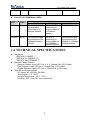
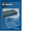
24-Port 10/100Mbps
+2-Port 10/100/1000Mbps Gigabit
Switch
ESW-8826
User's Guide
The Switch User’s Guide
Trademarks············································································································· 3
Copyright Statement ······························································································ 3
Preface ···················································································································· 3
FCC Warning·························································································································· 3
CE Mark Warning ··················································································································· 3
About This Guide ··································································································· 3
Purpose ·································································································································· 3
Terms/Usage ·························································································································· 3
Notes, Notices, and Cautions································································································· 4
Introduction ············································································································ 5
1.1 Gigabit Ethernet Technology ···························································································· 5
1.2 Fast Ethernet Technology ································································································ 5
1.3 Switching Technology······································································································· 6
1.4 Key Features ···················································································································· 6
1.4.1 Hardware Interface ································································································ 7
1.4.2 Performance Features ··························································································· 7
1.5 Panel ································································································································ 7
1.5.1 Front Panel Components······················································································· 7
1.5.2 Rear Panel ············································································································· 7
1.5.3 LED indicators information····················································································· 8
1.6 TECHNICAL SPECIFICATIONS ······················································································ 9
Installation ············································································································ 10
2.1 Installation method ········································································································· 10
2.2 Desktop or Shelf Installation ·························································································· 10
2.3 Rack Installation ············································································································· 10
2.4 Power on the Switch ······································································································ 10
Connecting the switch··························································································11
3.1 PC to Switch····················································································································11
3.2 Hub to Switch ··················································································································11
3.3 Switch to Switch (other devices) ·····················································································11
3.4 Port Speed & Duplex Mode·····························································································11
2
The Switch User’s Guide
Trademarks
Copyright @ 2006 _________ Corporation.
_________ is a registered trademark of ______ Corporation/______ Systems, Inc.
All other trademarks belong to their respective proprietors.
Copyright Statement
No part of this publication may be reproduced in any form or by any means or used
to make any derivative such as translation, transformation, or adaptation without
permission from _________ Corporation/_________ Systems Inc., as stipulated by
the United States Copyright Act of 1976.
Preface
FCC Warning
This device has been tested and found to comply with limits for a Class a digital
device, pursuant to Part 15 of the FCC Rules. These limits are designed to provide
reasonable protection against harmful interference when the equipment is operated
in a commercial environment. This equipment generates, uses and can radiate radio
frequency energy and, if not installed and used in accordance with the user’s
manual, may cause interference in which case the user will be required to correct
the interference at his own expense.
CE Mark Warning
This is a Class A product. In a domestic environment, this product may cause radio
interference in which case the user may be required to take adequate measures.
About This Guide
Congratulations on your purchase of the 8/16/24-Port 10/100Mbps+ 1-Port 100Mbps
FIBER Management Switch. This device integrates 100Mbps Fast Ethernet and
10Mbps Ethernet network capabilities in a highly flexible package.
Purpose
This User’s guide tells you how to install you’re the Switch how to connect it to your
Ethernet network, and how to set its configuration using the built-in Web-based
management.
Terms/Usage
In this manual, the term “Switch” (first letter upper case) refers to your 8/16/24-Port
3
The Switch User’s Guide
10/100Mbps+1-Port 10/100Mbps FIBER Management Switch, and “switch” (first
letter lower case) refers to other Ethernet switches.
Notes, Notices, and Cautions
NOTE: A NOTE indicates important information that helps you make better use
of your device.
NOTICE: A NOTICE indicates either potential damage to hardware or loss of
data and tells you how to avoid the problem.
CAUTION: A CAUTION indicates a potential for property damage, personal
injury, or death.
4
The Switch User’s Guide
1
Introduction
The Switch is equipped with 24-Port 10/100Mbps+ 2-Port 1000Mbps Gigabit Dump
Switch. The Switch is an effective solution for the backbone network. This all-in-one
solution economically integrates Gigabit technology to remove server bottlenecks,
and speed up access to the network backbone.
Figure 1-1
Figure of the Switch
1.1 Gigabit Ethernet Technology
Gigabit Ethernet is an extension of IEEE 802.3 Ethernet utilizing the same packet
structure, but with a tenfold increase in theoretical throughput over 100-Mbps Fast
Ethernet and a hundredfold increase over10-Mbps Ethernet. Since it is compatible
with all 10-Mbps and 100-Mbps Ethernet environments, Gigabit Ethernet provides a
straightforward upgrade without wasting a company’s existing investment in
hardware, software, and trained personnel.
The increased speed and extra bandwidth offered by Gigabit Ethernet is essential to
coping with the network bottlenecks that frequently develop as computers and their
busses get faster and more users use applications that generate more traffic.
Upgrading key components, such as your backbone and servers to Gigabit Ethernet
can greatly improve network response times as well as significantly speed up the
traffic between your subnets. Gigabit Ethernet enables fast optical fiber connections
to support video conferencing, complex imaging, and similar data-intensive
applications. Likewise, since data transfers occur 10 times faster than Fast Ethernet,
servers outfitted with Gigabit Ethernet NIC’s are able to perform 10 times the
number of operations in the same amount of time. In addition, the phenomenal
bandwidth delivered by Gigabit Ethernet is the most cost-effective method to take
advantage of today and tomorrow’s rapidly improving switching and routing
internetworking technologies. And with expected advances in the coming years in
silicon technology and digital signal processing that will enable Gigabit Ethernet to
eventually operate over unshielded twisted-pair(UTP) cabling, outfitting your
network with a powerful 1000-Mbpscapable backbone/server connection creates a
flexible foundation for the next generation of network technology products.
1.2 Fast Ethernet Technology
Ethernet, along with its speedier counterpart Fast Ethernet, is the most popular
networking standard in use today. 100Base-T Fast Ethernet is an extension of the
10Base-T Ethernet standard, designed to raise the data transmission capacity of
10Base-T from 10Mbits/sec to 100Mbits/sec. An important technology incorporated
by 100Base-T is its use of the Carrier Sense Multiple Access with Collision Detection
5
The Switch User’s Guide
(CSMA/CD) protocol, which is the same protocol that 10Base-T uses, because of its
ability to work with several different types of cable, including basic twisted-pair wiring.
Both of these features play an important role in network considerations, and they
make 100Base-T an attractive migration path for those networks based on 10Base-T.
Since the 100Mbps Fast Ethernet is compatible with all other 10Mbps Ethernet
environments, it provides a straightforward upgrade and takes advantage of the
existing investment in hardware, software, and personnel training.
1.3 Switching Technology
Switching is a cost-effective way of increasing the total network capacity available to
users on a LAN. If an Ethernet network begins to display symptoms of congestion,
low throughput, slow response times, and high rates of collision, installing a switch to
a network can preserve much or all of the existing network's cabling and workstation
interface card infrastructure while still greatly enhancing the throughput for users. A
switch is a viable solution even if demanding applications, such as multimedia
production and video conferencing, are on the horizon. The most promising
techniques, as well as the best return on investment, could well consist of installing
the right mixture of Ethernet switches.
A switch increases capacity and decreases network loading by dividing a local area
network into different LAN segments. Dividing a LAN into multiple segments is one
of the most common ways of increasing available bandwidth. If segmented correctly,
most network traffic will remain within a single segment, enjoying the full-line speed
bandwidth of that segment. Switches provide full-line speed and dedicated
bandwidth for all connections. This is in contrast to hubs, which use the traditional
shared networking topology, where the connected nodes contend for the same
network bandwidth. When two switching nodes are communicating, they are
connected with a dedicated channel between them, so there is no contention for
network bandwidth with other nodes. As a result, the switch reduces considerably
the likelihood of traffic congestion. For Fast Ethernet networks, a switch is an
effective way of eliminating the problem of chaining hubs beyond the “two-repeater
limit.” A switch can be used to split parts of the network into different collision
domains, making it possible to expand your Fast Ethernet network beyond the
205-meter network diameter limit for 100BASE-TX networks. Switches supporting
both traditional 10Mbps Ethernet and 100Mbps Fast Ethernet are also ideal for
bridging between existing 10Mbps networks and new 100Mbps networks. Switching
LAN technology is a marked improvement over the previous generation of network
hubs and bridges, which were characterized by higher latencies. Routers have also
been used to segment local area networks, but the cost of a router, and the setup
and maintenance required make routers relatively impractical. Today switches are
an ideal solution to most kinds of local area network congestion problems.
1.4 Key Features
The Switch was designed for easy installation and high performance in an
environment where traffic on the network and the number of users increase
continuously.
6
The Switch User’s Guide
1.4.1 Hardware Interface
l
l
l
l
l
l
l
24-Port 10/100Mbps+ 2-Port 10/100/1000M Gigabit
24×10/100Mbps Auto-negotiation Fast Ethernet RJ45 ports
2 BASE-T/SFP ports
All RJ45 ports support auto MDI/MDIX, so there is no need to use cross-over
cables or an up-link port
Full-/half- duplex transfer mode for 10/100Mbps Fast Ethernet transmission
Wire speed reception and transmission
Fully compliant with IEEE 802.3 10BASE-T, IEEE 802.3u 100BASE-TX and
IEEE802.3ab 1000BASE-T
1.4.2 Performance Features
l
l
l
l
l
8.8 G bps switching fabric capacity
Support 8K MAC address.
512KBytes packet buffer
Wire speed packet forwarding rate per system.
Store and forward switching scheme.
1.5 Panel
1.5.1 Front Panel Components
The front panel of the Switch consists of LED indicators, 24-Port 10/100Mbps+
2-Port 10/100/1000Mbps Gigabit. The figure below shows the front panels of the
Switch.
10/100 Base-TX Twisted-Pair Ports
1000Mbps GIGA
Figure 1-2
l
l
l
Front Panel view of the Switch
10/100BASE-TX Twisted-Pair Ports (Port1~24): These ports support network
speeds of either 10Mbps or 100Mbps, and can operate in half- and full- duplex
transfer modes. These ports also support automatic MDI/MDI-X crossover
detection, giving true “plug and play” capability. Just need to plug-in the network
cable to the hub directly and don’t care if the end node is NIC (Network Interface
Card) or switch and hub.
10/100/1000M Gigabit Ports (Port 25,26)
LED Indicator: Comprehensive LED indicators display the status of the switch
and the network (see the LED Indicators chapter below).
1.5.2 Rear Panel
7
The Switch User’s Guide
Figure 1-3
l
l
Rear Panel view of the Switch
AC Power Connector: This is a three-pronged connector that supports the power
cord.
In the female connector of the provided power cord into this connector, and the
male into a power outlet. Supported input voltages range from220V AC at 50Hz.
NOTICE:
Do not envelop Radiator Fan while the Switch is working.
1.5.3 LED indicators information
The front panel LEDs provides instant status feedback, and, helps monitor and
troubleshoot when needed.
Figure 1-4
l
POWER: Power Indicator
LED
PWR
l
Front Panel view of the switch
Status
Solid
Blinking Off
Green When the Power LED N/A
Connected properly.
lights on, the Switch is
receiving power
Color
Ports 1~24 10/100M Status LEDs
LED
Color
LINK/ACT
Green
10/100M
Green
Status
Solid
Blinking
The respective port The port is
is successfully
transmitting or
Connected to an
receiving data on
Ethernet network.
the Ethernet
network.
The respective port N/A
is connected to
The 100Mbps
8
Off
No link.
The respective port
is connected to the
10Mbps Ethernet
The Switch User’s Guide
Ethernet network.
l
network.
Ports 25~26 1000M Status LEDs
LED
Color
L/A
Green
1000M
Green
Solid
The respective port
is successfully
connected to an
Ethernet network.
The respective port
is connected to The
100Mbps Ethernet
network.
Status
Blinking
The port is
transmitting or
receiving data on
the Ethernet
network.
The port is
transmitting or
receiving data on
the 1000Mbps
Ethernet network.
Off
No link.
The respective port
is connected to the
10Mbps or 100Mbps
Ethernet network.
1.6 TECHNICAL SPECIFICATIONS
l
l
l
Standards:
IEEE 802.3 10BASE –T
IEEE 802.3u 100BASE -TX
IEEE 802.3ab 1000BASE -T
Network Cables: Cables:
Ethernet: Cables: 2-pair UTP Cat. 3, 4, 5, Twisted Pair (UTP) Cable
Fast Ethernet: 2-pair UTP Cat. 5, Twisted Pair (UTP) Cable
Gigabit Ethernet: 4-pair UTP Cat. 5, Twisted Pair (UTP) Cable
Physical and Environmental
DC inputs: AC 100-220V 50-60Hz
Temperature: 0 °C ~50°C
Storage Temperature: -20°C ~ 70°C
Humidity: 10% ~ 90% RH, non-condensing
9
The Switch User’s Guide
2
Installation
The site where you place the switch may greatly affect its performance. When
installing, take the following into your consideration.
2.1 Installation method
Follow the guidelines below to install the Switch.
Install the Switch in a fairly cool and dry place. See the Technical Specifications for
the acceptable temperature and humidity operating ranges.
Install the Switch on a sturdy, level surface that can support its weight, (at least 4KG)
Connect the power cord to the Switch and the power outlet. The distance is no more
than 182cm.
Leave at least 10cm (about 4 inches) of space at the front and rear of the Switch for
ventilation.
2.2 Desktop or Shelf Installation
When installing the Switch on the desktop or shelf, please attach the rubber feet to
the Switch. Peel off the protective paper on the pads and attach them on the bottom
of the Switch (one at each corner).
2.3 Rack Installation
The Switch is rack-mountable and can be installed on an EIA-19 inch equipment
rack. To do this, first install the mounting brackets on the Switch’s side panels (one
on each side), secure them with the included screws, and then use the screws
provided with the equipment rack to mount the Switch on the 19inch rack.
2.4 Power on the Switch
The Switch has a universal power supply ranging from 100V to 220V AC, 50 ~ 60Hz
power source. The AC power connector is located at the rear of the unit adjacent to
and the system fan. The switch’s power supply will adjust to the local power source
automatically.
10
The Switch User’s Guide
3
Connecting the switch
This chapter describes how to connect the Switch to your Fast Ethernet network.
3.1 PC to Switch
Figure 3-1 PC to Switch
A PC can be connected to the Switch via a two-pair Category 3, 4, or 5 UTP/STP
straight-through Cable. For 100Mbps operation Category 5 must be used. The PC
(equipped with a RJ-45 10Mb Ethernet or 100Mb Fast Ethernet NIC) should be
connected to any port of the Switch. The LED indicators for PC connection are
dependent on the LAN card capabilities. If the LED indicators do not light after
making a proper connection, check the PC LAN card, the cable, the Switch
conditions and connections.
3.2 Hub to Switch
A hub (10 or 100BASE-TX) can be connected to the Switch via a two-pair Category
3, 4, or 5 UTP/STP straight cable. For 100Mbps operation a Category 5 cable must
be used. The connection is accomplished from any port of the hub to any port of the
Switch.
3.3 Switch to Switch (other devices)
The Switch can be connected to another switch or other devices (routers, bridges,
etc.) via a two-pair Category 3, 4, 5 UTP/STP straight or crossover cable. A
Category 5 cable must be used for 100Mbps operation. The connection can be done
from any (MDI-X) port of the Switch (Switch A) to any of the 10Mbps, 100Mbps
(MDI-X) port of the other switch (switch B) or other devices.
3.4 Port Speed & Duplex Mode
After plugging the selected cable to a specific port, the system uses auto-negotiation
to determine the transmission mode for any new twisted-pair connection:
If the attached device does not support auto negotiation or has auto-negotiation
11
The Switch User’s Guide
disabled, an auto sensing process is initiated to select the speed and set the duplex
mode to half-duplex.
12