1
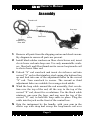
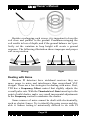
TDI SL White’s Electronics, Inc. Sweet Home, Oregon USA Building the World’s Finest metal detectors for over 60 years. TDI SL Owner’s Manual CONTENTS Assembly . . . . . . . . . . . . . . . . . . . . . . . . . . . . . . . . . . . . . . . . . 3 Batteries and Charger . . . . . . . . . . . . . . . . . . . . . . . . . . . . . . . . 5 QuickStart . . . . . . . . . . . . . . . . . . . . . . . . . . . . . . . . . . . . . . . . . 6 Principles of Pulse Induction . . . . . . . . . . . . . . . . . . . . . . . . . . 7 Controls Threshold . . . . . . . . . . . . . . . . . . . . . . . . . . . . . . . . . . . . . . 9 Power/gain . . . . . . . . . . . . . . . . . . . . . . . . . . . . . . . . . . . . . 9 Pulse Delay . . . . . . . . . . . . . . . . . . . . . . . . . . . . . . . . . . . . 10 Target Conductivity. . . . . . . . . . . . . . . . . . . . . . . . . . . . . . 11 Ground Balance . . . . . . . . . . . . . . . . . . . . . . . . . . . . . . . . 12 Frequency . . . . . . . . . . . . . . . . . . . . . . . . . . . . . . . . . . . . . 13 TDI In Depth Ground Balancing . . . . . . . . . . . . . . . . . . . . . . . . . . . . . . . 14 Audio . . . . . . . . . . . . . . . . . . . . . . . . . . . . . . . . . . . . . . . . 14 Pulse Delay . . . . . . . . . . . . . . . . . . . . . . . . . . . . . . . . . . . . 17 Dual-field coil . . . . . . . . . . . . . . . . . . . . . . . . . . . . . . . . . . 18 Dealing with Noise . . . . . . . . . . . . . . . . . . . . . . . . . . . . . . 20 Specifications . . . . . . . . . . . . . . . . . . . . . . . . . . . . . . . . . . . . . 22 Warranty . . . . . . . . . . . . . . . . . . . . . . . . . . . . . . . . . . . . . . . . . 23 Code of Ethics. . . . . . . . . . . . . . . . . . . . . . . . . . . . . .Back Cover Page 2 TDI SL Owner’s Manual Assembly Search coil Lower rod Arm cup Rubber washers (2), fiber bolt Clevis Cam lock Battery door 1. Remove all parts from the shipping carton and check assembly diagram to ensure all parts are present. 2. Install black rubber washers on fiber clevis/lower rod, insert clevis lower rod onto loop ears. Use only nonmetallic washers, fiber bolt, and fiber thumb nut to secure loop/search coil to clevis/lower fiber rod. 3. Unlock “S” rod cam-lock and insert clevis/lower rod into curved “S” rod so that stainless steel spring clip buttons line up and lock into one of the adjustment holes in the curved “S” rod. Turn cam-lock to secure. The second or third adjustment holes are suitable for average sized adults. 4. Wind the loop cable around the rod assembly, first revolution over the top of the rod, all the way to the top of the curved “S” rod, about five revolutions. Use the black cable retainers, one near the loop, and one near the top of the curved “S” rod, to hold the loop cable in place. Plug the cable into the jack on the front of the control box. 5. Grip the instrument by the handle, with your arm in the elbow cup with strap and sweep the loop/search coil over Page 3 TDI SL Owner’s Manual the floor. If the instrument fit feels uncomfortable, readjust clevis/lower rod length with spring clip button and camlock so that search coil can be held near the floor without stooping over. 6. Remove the protective paper from the two black arm cup foam pads. Carefully align pads on the inside of the elbow cup, one on each side of the center rod, and press firmly into place. 7. Adjust the elbow cup strap so that it is loose enough for you to slide your arm in and out without loosening each time you want to set the detector down. The elbow cup strap provides extra leverage and control. However, some prefer not to use it. 8. Install the battery pack; see the next section for information on batteries and charging. Page 4 TDI SL Owner’s Manual Batteries and Charger The TDI-SL includes a rechargeable NiMH battery pack as the primary power source, and a standard alkaline battery pack as a backup. Fully charged, they supply a nominal 12 volts (the NiMH may be slightly less) and will power the TDI-SL for about 4-5 hours. The TDI will operate until the batteries drop to about 8.5 volts, at which point the low battery LED will turn on. A drop-in charging cradle (Part Number 509-0036) is used for recharging the NiMH battery. With the wall transformer connected to the cradle and plugged into a wall socket, simply drop the NiMH pack into the cradle. An LED indicates the status of the charge cycle; when the LED turns off, the charge cycle is complete and the charger will automatically switch to a trickle mode. A typical recharge time of a depleted NiMH pack is 1-2 hours. It is normal for NiMH batteries in storage to slowly lose their charge over time; be sure to top off them off before going out. The alkaline pack is designed so that it cannot be used with the charger, and trying to recharge alkaline batteries can cause them to burst and leak. Individual NiMH batteries can be used in the alkaline tray; it is recommended that the batteries be removed and charged using the manufacturer’s charging system. Page 5 TDI SL Owner’s Manual QuickStart 1. Set the Conductivity switch to ALL. 2. Set the Frequency offset to the midpoint. 3. Set the Ground Balance to ~8. 4. Turn on the power and adjust the Gain to “2.” 5. Adjust the Threshold to achieve a faint background hum. 6. With the coil on the ground (no motion) increase the Gain until the audio begins to chatter. Back off slightly for a reasonably smooth threshold. 7. Optional: adjust the Frequency offset to minimize the amount of chatter. 8. Using a spot free of targets, bob the coil up & down and adjust the Ground Balance control to minimize the audio response. 9. For most nugget hunting, set the Conductivity switch to LOW. Page 6 TDI SL Owner’s Manual Principles of Pulse Induction Pulse induction (PI) detectors are very different from traditional induction-balance (VLF) designs. Instead of transmitting a continuous-wave magnetic field, the PI detector periodically transmits brief impulses of magnetic energy. The PI receiver then looks at the impulse decay for target (and ground) information. Pulse Rate TX Exponential decay RX The use of high-powered impulses results in better ground penetration than VLF, especially in highly mineralized soil. This makes the PI detector the best choice for certain kinds of hunting in bad ground where many VLFs simply won’t work. There is no traditional discriminator in PI detectors, although there is some ability to discern certain types of metals. The decay response varies with target conductivity (plus other characteristics) so that low conductive targets have a fast decay and high conductive targets have a slow decay: Low-conductive target, fast decay High-conductive target, long decay No target Raw Response The Pulse Delay control, which determines the point where the decay is sampled, can be used to eliminate low conductive targets such as thin foil. Further increasing the delay can knock Page 7 TDI SL Owner’s Manual out other minor trash targets at the expense of eliminating potentially good targets such as jewelry, but this method is very limited in the range of trash targets that are rejected. Furthermore, the ground balancing method used by TDI has a side affect with target responses. Target conductivities below the ground balance point produce a positive response for which TDI assigns a high tone. These targets are generally low conductive such as small nuggets, jewelry, and small iron. Target conductivities above the ground balance point produce a negative response for which TDI assigns a low tone. These targets are generally high conductive such as silver coins, relics, and large iron. Low-conductive target No target High-conductive target Ground balance point Differential Response The Target Conductivity switch can be used to eliminate either class of targets, or to accept them all. Care should be used with this feature as it is not always obvious as to how a target might respond. Testing with known targets is the best way to learn the responses, both with delay settings and conductivity mode. Page 8 TDI SL Owner’s Manual Controls Threshold The Threshold control sets the level at which the background audio tone is heard. In most cases, faint target signals are easiest to hear when the threshold is set to a low but clearly audible level. A higher threshold level can result in audio fatigue. Too low of a threshold level means that a stronger target signal is required to produce an audible change. Threshold is best determined at a low gain setting where there is no chatter. The threshold can be set low enough to effect a “silent search” audio. Some people prefer silent search to prevent audio fatigue. If you choose to do this, increase the threshold to the point where you can hear the threshold tone, then slowly back off until it is barely inaudible. Reducing the threshold any more than necessary requires stronger target signals to produce an audio response. Other controls — including Gain, Ground Balance, and Frequency offset — are best adjusted with an audible threshold. Power/Gain The Gain control increases or decreases the amplification of the receive signal. Normally, this determines how deep the detector will “see” a target. However, increasing the gain not only increases the amplification of target signals, but also that of ground signals and electromagnetic interference (EMI) as well. A common mistake is to assume Page 9 TDI SL Owner’s Manual that higher gain will always give better depth. In air tests this is generally true, but ground results can depend on the amount and type of mineralization. With the coil on the ground, increase the gain until the detector exhibits chatter, then back off slightly for a reasonably steady threshold tone. Use the Frequency offset control to help deal with EMI-related chatter, and proper ground balancing will minimize chatter due to mineralization. The Gain control is also used to turn the detector on and off. Pulse Delay TDI transmits a pulse and then, after a short time delay, samples the received signal. Pulse Delay allows this time delay to be adjusted from 10s (microseconds) to 25s. In response to a transmitted impulse, all targets exhibit a response with an exponential decay. Regardless of conductivity, the response is strongest at low sample delays and weaker at higher delays. However, targets of low conductivity or that are thin will decay faster than highly conductive or thick targets. See the Principles of Pulse Induction section for more details. Smaller gold nuggets fall in the former category, so nugget hunters will want the Pulse Delay set as low as possible. Coin or relic hunters may want to increase the delay to knock out thin foil trash and still detect desirable targets. Most iron (especially larger) responds with a long decay and is usually not very responsive to the delay setting. Conductive salts also respond with a fast decay and can be detected at low delay settings. If beach hunting in wet salt sand, you may need to turn the delay up to 15s to eliminate the salt response. Dry salt is usually not a problem, so as you move out of the wet sand into dry sand remember to turn the delay back down to better detect small jewelry items. Page 10 TDI SL Owner’s Manual Pulse Delay affects the ground balance point, so whenever the delay is changed the ground balance should also be checked and re-adjusted. Higher pulse delays require a lower ground balance setting. Target Conductivity The Target Conductivity switch allows you to select between high-only, low-only, or all target responses (see the Principles of Pulse Induction section for details). There are two caveats with this switch. First, the two-tone response, and therefore the functionality of this switch, are disabled when ground balance knob is turned to the OFF position. Second, in order to ground balance the TDI this switch must be set to the ALL position. Be aware that target conductivities can vary considerably, even targets of the same metal. Small gold nuggets are usually low and large gold nuggets are usually high, but where the transition occurs depends on the composition of the gold alloy. Be mindful that searching in low-conductivity mode could eliminate very large nuggets, if any happen to be in the area1. The same is true for relics and jewelry. Many bullets, buttons, and most buckles register as high conductors, but cuff buttons often respond as low conductors. Most small jewelry responds as low conductors, but larger men’s rings can easily fall in the high-conductive range. Most coins fall in the high range, except for e.g. US nickels and small or thin coins like hammered silvers or very small bronze coins. 1. The potential for Very Large Nuggets depends on where you are detecting. In most gold-bearing regions of the US, detectable gold is found as small placer nuggets up to multiple grams in size which register as low conductive targets. Alaskan and Australian gold is still being found in multiple ounce-sized nuggets, which may respond as a high conductive target. Page 11 TDI SL Owner’s Manual Ground Balance This control is used to balance out the signal from ground mineralization. There is an OFF position for which TDI runs in straight PI mode with no ground balance. To ground balance TDI the Target Conductivity control must be set to ALL in order to hear both conductivity tones. Set the Gain to about the mid-point or until the audio just begins to chatter. Pump the search coil up and down from about one inch off the ground up to 6-8 inches above the ground while listening for a change in the audio. If the GB is too low, the audio will have a high tone when the coil is lowered to the ground; if the GB is too high, the audio will have a low tone. Adjust the Ground Balance control for minimal audio changes. For most moderate mineralization, this will be around “8”. A simple technique is to start with the GB set intentionally too low (say, 5), then pump the coil and increase the GB until the high tone begins to transition to a low tone. If the Pulse Delay control is changed, you will probably need to re-adjust the Ground Balance setting. In addition, if you begin to hear ground noises (false signals) as you sweep the coil you should check the ground balance. There are some cases where a particular target will fall exactly on top of the ground balance point and TDI will not be able to detect it at all. Targets that are close to the ground balance point may have their response shifted if the Ground Balance control is adjusted. For example, a given target may have a low conductor response with GB=9 but a high conductor response at GB=5. Turning the Ground Balance to the OFF position disables the ground balance and TDI will run as a straight PI detector. This gives a slight improvement in depth but, of course, will respond to mineralization and eliminates the ability to discern conductivities. Page 12 TDI SL Owner’s Manual Frequency This control makes small adjustments to the transmitter pulse rate. This is used to counteract any interference which might be due to outside electromagnetic sources, such as radio stations, microwave, short wave, electric fences, power lines, lightening, electrical storms, or other metal detectors being used nearby. This interference is recognized by a warbling or repetitive pulsing of the audio threshold, and can mask target signals. If you are experiencing interference, adjust the Frequency control for minimal chatter. Adjustments should be done in small steps, with a few seconds between each adjustment to see if the TDI settles down. If you cannot deal with interference with the Frequency control, then reduce the Gain and/or Threshold settings to obtain a reasonably stable operating point. Page 13 TDI SL Owner’s Manual TDI In Depth Ground Balancing One of the key features of TDI is its ability to balance out ground mineralization while maintaining pulse induction depths. This is achieved using a differential technique whereby two decay samples are compared; the Ground Balance control is adjusted until the two samples have the same response, thereby canceling the ground signal. Targets below the GB point produce an overall positive response, and targets above the GB point produce an overall negative response. Broadly, the two ranges of targets depend on conductivity, which gives TDI some ability to discriminate. In rare cases a target might fall so close to the GB point that it gives either no response at all or a double-tone response. Because ground balance is achieved using a subtraction method, there is a slight loss of depth any time ground balance is on. Some ground, notably neutral beach sand, is mild enough that no ground balance is needed. In such cases, Ground Balance can be switched off and TDI will run in straight PI mode. This will slightly improve depth, but loses the ability to distinguish between low and high conductivity targets. Audio TDI has the following audio tonal responses: Ground Balance Conductivity Mode On On On Off High All Low ‐‐‐ Audio Tones Low High Conductor Conductor ‐‐‐ Low High Low High ‐‐‐ High High Page 14 TDI SL Owner’s Manual With Ground Balance = On and Conductivity Mode = All, all targets will give an audio response, either a high or low tone. New users are encouraged to use this setup and practice with various targets to learn their audio responses. A US nickel or small gold nugget works well for a low conductive target, and a US quarter makes a good high conductive target. TDI is a motion detector, so target responses depend on the motion of the coil. If you hold the coil steady over a target, the audio response will fade back to the threshold tone. In some cases there is not enough mineralization to require ground balancing (e.g. non-mineralized beaches), and Ground Balance may be turned off. In this mode the audio response is high for all targets. In cases where you have determined that you definitely need only one of the conductivity modes and not the other, you will often find that switching to that mode reduces the amount of audio noise (chatter) and allows you to run a higher gain. To better illustrate this, let’s use a strictly inaccurate but useful diagram. The following is a representation of the audio response, including a low conductor response, a high conductor response, and random noise: Low-conductor response Noise Target Conductivity = ALL Ideal no-noise response High-conductor response The ideal no-noise response is what you would get if you disconnect the search coil. With Target Conductivity = All, anything above the ideal response will have a high tone and anything below the ideal response will have a low tone. If there is a lot of EMI or the Gain is set aggressively high this can result in a lot of audio chatter. Page 15 TDI SL Owner’s Manual Setting the Target Conductivity to either Low or High will cut out half of the response, as shown in the next diagrams. The Target Conductivity = LOW Target Conductivity = HIGH noise, which tends to be equally distributed between the high and low tones, is cut in half. However, you also lose one of the conductivities. If you know you primarily want to hunt small to medium nuggets or fine jewelry, then you will not lose much running in the Low mode. If you primarily want to hunt coins or relics, then you will not lose much running in the High mode. Be mindful that “All” is required for ground balancing, because that is the only mode that gives you both tones. Threshold also has an effect on how much noise gets through to the audio. A moderate threshold lets some of the noise through (anything in the gray region is suppressed): In this case you will hear a moderate amount of chatter, depending on the Gain setting. Weak target signals may come through but may be indistinguishable from noise. Page 16 TDI SL Owner’s Manual A lower threshold makes the TDI quieter and less chattery but also requires a stronger target signal to produce a tonal response: A lower threshold can be played off against a higher Gain setting, although you may find that the net outcome is about the same. Setting the threshold exceptionally low can result in a “silent search” audio, whereby there is no audio sound until a target is detected: The drawback is that sensitivity can be markedly reduced and weaker targets completely eliminated. However, Gain can be increased to counter this, though the net result is still likely to be less sensitivity than an optimally adjusted threshold. Pulse Delay Sampling as close as possible to the end of the transmitted pulse gives the highest sensitivity to all metal targets regardless of their size or conductivity. As the Pulse Delay is increased toward 25s low-conductive targets will drop out, leaving only the more high-conductive targets. Conductivity is not the only factor that determines how targets respond; size, thickness, and shape also have a strong influPage 17 TDI SL Owner’s Manual ence. Sub-gram gold nuggets are often only detectable at the lowest delay setting while larger nuggets, even of the same alloy, can be detected at higher delay settings. This is largely due to skin effect, whereby the response of small thin targets dissipates quickly. A good exercise is to experiment with different targets at different Pulse Delay settings. This is best done with the Ground Balance switched off so that all targets sound the same (no twotone response) and the sensitivity to the target can be more easily observed. After you determine how the Pulse Delay affects the signal, you can try the same tests with the Ground Balance turned on and the Target Conductivity to All to see whether the target produces a high tone or a low tone. You can then choose Low or High to eliminate or accept a target. In some soils the minimum pulse delay cannot be used. Notably wet salt soil (such as a saltwater surf zone) behaves like a low-conductor target and will respond regardless of the Ground Balance setting. Increasing the Pulse Delay to about 15s will eliminate wet salt response. However, as you move out of the surf zone onto dry sand remember you can reduce the Pulse Delay to maximize sensitivity as dry salt sand does not cause a problem. Areas with high concentrations of black sand may also require an increase in the Pulse Delay. Any changes to the Pulse Delay setting affects the ground balance point so the TDI will need to be re-balanced. Dual Field Coil With any metal detector, the size of the search coil presents a trade-off between depth and sensitivity. A larger coil offers better depth on larger targets at the expense of small-target sensitivity, and a smaller coil has better sensitivity to small targets, but at a lesser depth. Detectable gold nuggets can range from several grains to multiple ounces, so a coil that offers both depth and sensitivity would be ideal. TDI uses a patented dual field (DF) coil which Page 18 TDI SL Owner’s Manual literally gives you two different size coils running simultaneously: a larger outer coil for large target depth, and a smaller inner coil for small target sensitivity. As such, even the 12” DF coil, with its 6” inner coil, can pick up nuggets of only a few grains. The 7” DF coil, with its 3.5” inner coil, is even better at picking up grain-sized nuggets, with little compromise on large target depth. Proper sweep technique is important with any detector, and the DF coil adds a slight twist. Round coils tend to have a conical pattern of sensitivity as illustrated below. As such, coverage at maximum depth is less than the size of the coil, so it is always recommended that successive sweeps are overlapped by about 50%. The DF coil has an additional inner coil which has its own conical detection pattern. Since this coil is most sensitive to shallower tiny targets that the larger coil may miss, in order to get the best ground coverage on these targets it is recommended that the 50% overlap be applied to the inner coil, as illustrated below. Page 19 TDI SL Owner’s Manual Besides overlapping each sweep, it is important to keep the coil close and parallel to the ground. Pendulum-swinging the coil results in loss of depth, and if the ground balance isn’t perfectly set the variation in loop height will create a ground response. The following illustration shows improper and proper coil sweep motion. Wrong Right Dealing with Noise Because PI detectors have wideband receivers they are more prone to noise and interference than narrowband VLF designs. There are a few strategies for dealing with noise. First, TDI has a Frequency Offset control that slightly adjusts the overall pulse rate. With the Threshold and Gain turned up to the point of mild chatter, make very small incremental adjustments to the Frequency control to minimize the chatter. Some sources of noise cannot be dealt with electronically, such as electric fences. Try to identify the noise source and disable it. Indoor testing is notoriously difficult to do with PI Page 20 TDI SL Owner’s Manual detectors due to the overwhelming number of EMI sources. If you cannot minimize noise with the Frequency control, then turning down the Gain or Threshold is your best bet. Excessive chatter will easily mask targets, plus results in audio fatigue. It is better to trade off sensitivity for smooth audio so you can hear the targets. Page 21 TDI SL Owner’s Manual TDI-SL Specifications Operating mode . . . . . . . . . . . . . . . . . . . . . . . . Pulse Induction Pulse Frequency . . . . . . . . . . . . . . . . . . . . . . . . 2.6kHz - 3kHz Pulse Delay. . . . . . . . . . . . . . . . . . . . . . . . . . . . . . .10s - 25s Search modes . . . . . . . . . . . . . . . . . . PI, Ground balanced PI Ground balance . . . . . . . . . . . . . . . . . . . . . . .Differential delay Audio tones . . . . . . . . . . . . . . . . . . . . . . . . . . . . . . . . . . 1 or 2 Audio output . . . . . . . . . . . . . . . . . . . . .Speaker, headphones Search coil . . . . . . . . . . . . . . . . . . . . . . . . . . . . 7.5” Dual Field 12” Dual Field Weight. . . . . . . . . . . . . . . . . . . . . . . . . . . . . 3 lbs (7.5” DF coil) 3.5 lbs (12” DF coil) Length. . . . . . . . . . . . . . . . . . . . . . . .43 - 48 inches, adjustable Batteries . . . . . . . . . . . . . . . . . . . . . . . (8) AA, NiMH & alkaline Battery life . . . . . . . . . . . . . . . . . . . . . . . . . . 5-6 hours typical2 Warranty . . . . . . . . . . . . . . . . . . . . . . . . . 2 years, transferrable Customer Support Questions concerning your TDI-SL? There are three ways to contact us: Internet: http://whiteselectronics.com/support.html Phone: 1-800-547-6911 (US) (0044) 1463 223456 (UK) Or mail us: White's Electronics 1011 Pleasant Valley Road Sweet Home, OR 97386 2. 2200mAh NiMH batteries Page 22 White's Electronics 35 Harbour Road Inverness, Scotland IV1 1UA TDI SL Owner’s Manual Warranty If within two years (24 months) from the original date of purchase, your White’s detector fails due to defects in either material or workmanship, White’s will repair or replace at its option, all necessary parts without charge for parts or labor. Simply return the complete detector to the Dealer where you purchased it, or to your nearest Authorized Service Center. The unit must be accompanied by a detailed explanation of the symptoms of the failure. You must provide proof of date-of-purchase before the unit is serviced. This is a transferable manufacturer warranty, which covers the instrument two years from the original purchase date, regardless of the owner. Items excluded from the warranty are non-rechargeable batteries, accessories that are not standard equipment, shipping/handling costs outside the continental USA, Special Delivery costs (Air Freight, Next Day, 2nd Day, Packaging Services, etc.) and all shipping/handling costs inside the continental USA 90 days after purchase. White’s registers your purchase only if the Sales Registration Card is filled out and returned to the factory address by your dealer, soon after original purchase for the purpose of recording this information, and keeping you up-to-date regarding White’s ongoing research & development. The warranty does not cover damage caused by accident, misuse, neglect, alterations, modifications, unauthorized service, or prolonged exposure to corrosive compounds, including salt. Duration of any implied warranty (e.g., merchantability and fitness for a particular purpose) shall not be longer than the stated warranty. Neither the manufacturer or the retailer shall be liable for any incidental or consequential damages. Some states however, do not allow the limitation on the length of implied warranties, or the exclusion of incidental or consequential damages. Therefore, the above limitations may not apply to you. In addition, the stated warranty gives you specific legal rights, and you may have other rights which vary from state-to-state. The foregoing is the only warranty provided by White’s as the manufacturer of your metal detector. Any “extended warranty” period beyond two years, which may be provided by a Dealer or other third party on your detector, may be without White’s authority involvement and consent, and might not be honored by White’s Electronics, Inc. Page 23 TDI SL Owner’s Manual TDI SL Treasure Hunter’s Code of Ethics 1. Always check federal, state, county, and local laws before searching. 2. Always obtain the owner’s permission before accessing private property. 3. Take care to refill all holes and leave no trace. 4. Remove and dispose of any and all trash and litter found. 5. Whenever possible, return identifiable property to its rightful owner. 6. Never destroy historical or archaeological treasures. 7. Appreciate and protect natural resources, wildlife and property, both public and private. 8. Act as an ambassador for the hobby; be thoughtful, considerate, and courteous at all times. White’s metal detectors are proudly designed, built, and tested in Sweet Home, Oregon USA by the employees of White’s Electronics. Page 24