1
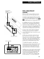
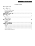
®
White's Electronics, Inc.
1011 Pleasant Valley Road
Sweet Home, OR 97386 USA
Distribution: 1-800-547-6911
Factory: 1-541-367-6121
FAX: 1-541-367-2968
Web Site: http://www.whiteselectronics.com
©White's Electronics, Inc.
P/N 621-0428
30
Printed in USA
Rev. 8/2001
Introduction
All White's ground canceling detectors are capable of finding gold nuggets in the ground.
However, none will perform as efficiently as the line of Goldmasters created especially for nugget
hunting. The new GMT is the culmination of a series of Goldmasters, refined and improved over
the years. With the addition of Fast Ground Tracking the GMT is the ultimate Goldmaster.
The reason the Goldmaster stands above all other detectors in finding gold nuggets is the
care taken to accommodate the particular conditions encountered while gold prospecting. Since
gold is most often found in highly mineralized soil, it was necessary to design a ground balance
circuit which had the range to cancel out both extremes (+) and (-) mineralization. The GMT has
made it easier to achieve and monitor ground rejection by utilizing digital microprocessor software to automatically track out (eliminate) ground mineralization. In addition to automatic elimination of ground minerals, the GMT retains the manual ground balancing system perfected for its
predecessor, the GM/4B. In this way, the GMT will satisfy both preferences, manual or automatic.
All of these refinements are enhanced by incorporating a new, state of the art, iron identification
system. This unique development applies digital analyzing to accurately predict the probability of
a target being iron and thus reduce the amount of iron trash being dug. This exclusive Iron I.D.
system is presented to the user both visually on the meter at all times and audibly when desired.
White's Iron I.D Probability System does not alter the depth detection of the GMT.
The GMT also retains the Variable SAT feature so popular with gold prospectors. By adjusting the
speed of the SAT (self adjusting threshold) the user can minimize the affects of fast changing
ground mineralization. This feature has long been an exclusive feature of White's Goldmasters.
Audio Signal Boost, engineers call this feature E.P.S. (Enhanced Signal Penetration), is retained
from previous Goldmasters and provides audio amplification (gain). Signal Boost will give a
louder signal on those very tiny or deep targets when needed in certain operating conditions.
The GMT is designed for use with the new 101/2" elliptical Twin-D searchcoil,which it is shipped
with. However, it is electrically compatible with all other Goldmaster searchcoils. The GMT
operates slightly below the operating frequency of previous Goldmaster models, so it can be used
near those older models with minimal "crosstalk". In addition, the GMT has added a unique
touch pad controlled "Grab" feature, which instantly achieves ground balance. This and a "follow
the gold" feature will be described in the manual.
All this adds up to a great detector for doing what we all love best, finding gold!
Good Luck and Good Prospecting!
Jimmy "Sierra" Normandi
29
GMT Table of Contents
NOTE: Due to Acrobat PDF limitations the Introductory page is on page 29
GMT Table of Contents
Chapter 1 Assembly ............................................................................... 2
Assembly Instructions ......................................................................................................................... 3
Chapter 2 Batteries ................................................................................. 4
Standard Battery Holder ...................................................................................................................... 4
Using the
Standard Battery Holder ................................................................................................................... 4
Rechargeable Battery(Opt.) ................................................................................................................. 5
Battery Check ...................................................................................................................................... 5
Chapter 3 GMT Quick Start .................................................................. 6
Quick Start
Instructions ....................................................................................................................................... 7
Chapter 4 Controls ................................................................................. 8
Gain Control/Power Off ...................................................................................................................... 8
Gain Adjustment .................................................................................................................................. 8
Gain Adjustment (cont'd) .................................................................................................................... 9
Audio Signal Boost Toggle ............................................................................................................... 10
Hot Rocks .......................................................................................................................................... 11
Variable SAT Speed Control.............................................................................................................. 11
VSAT Adjustment.............................................................................................................................. 11
Iron I.D. Trigger Adjustment ............................................................................................................. 12
Threshold Control ............................................................................................................................. 13
Threshold Adjustment ....................................................................................................................... 13
Ground Balance
Fast AutoTrac .................................................................................................................................. 14
Manual Ground Balance .................................................................................................................... 15
Ground Balance Adjustment ............................................................................................................. 15
Chapter 5 Searching............................................................................. 16
Pinpoint Technique ............................................................................................................................ 16
Headphones ....................................................................................................................................... 17
Field Use & Tuning Tips ................................................................................................................... 18
Field Use & Tuning Tips (cont'd) ...................................................................................................... 20
Field Use & Tuning Tips (cont'd) ...................................................................................................... 22
Chapter 6 Information.......................................................................... 24
Proper Care ........................................................................................................................................ 24
Service ............................................................................................................................................... 25
Warranty ............................................................................................................................................ 26
Warranty Transfer .............................................................................................................................. 27
Video and Owner Information ........................................................................................................... 28
1
Chapter 1 GMT Assembly
Assembly
WASHERS
BETWEEN
EACH LOOP
EAR & CLEVIS
CABLE RETAINERS
CLEVIS
LOWER
ROD
CENTER ROD
SECTION
METER / DISPLAY
1/ Iron I.D. % Probability Bar Graph
2/ Type of Minerallization ( 0 to 99 )
3/ Amount of Mineralization ( 0 to 99 )
4/ Battery Check Bar Graph or Message
5/ Overload Message
TOUCHPADS
1/ Grab
2/ Manual Gnd. Balance (-) (+)
CAMLOCKS
AUDIO.
IRON I.D.
TOGGLE
“S” ROD
HEADPHONE JACK
ELBOW
CUP
STRAP
LOOP CABLE
ELBOW CUP
FOAM PADS
INSIDE ELBOW
CUP
LOOP CONNECTOR
CONTROL BOX
BATTERY
COMPARTMENT
LATCHES
BATTERY
COMPARTMENT
DOOR
2
Chapter 1 GMT Assembly
Assembly Instructions
1. Remove all parts from shipping carton and
check the assembly page to make sure all parts are
present.
2. Unlock "S" rod camlock and insert the reduced
end of the center rod into curved "S" rod so that
stainless steel spring clip buttons line up and lock
into the holes in the curved "S" rod. Turn
camlock to secure.
3. Fit the rubber washers between clevis/lower
rod and searchcoil ears. Use only non-metallic
washers, fiber bolt, and thumbnut, to secure loop
to clevis/lower rod. Then insert into center rod so
that stainless steel spring buttons line up and lock
into one of the adjustment holes in the center rod.
Turn Camlock to secure.
4. Unravel cable and wind the cable around the
clevis and rod assembly, first revolution should be
OVER the top of the rod with some slack before
applying the cable retainer. This is done so that
the search coil can be paddled backwards toward
the rod without putting a strain on the cable.
Wind cable firmly all the way to the handle toggle
switch. Then plug connector into control box
turn lock ring to secure. To secure cable, wrap
velcro cable retainers around rod and cable, one
near the searchcoil and one near the toggle switch.
5. Grip the instrument by the handle, with your
arm in the elbow cup with strap secure, and sweep
the coil over the floor. If the instrument fit feels
uncomfortable, adjust the elbow cup by removing
and repositioning the bolt/thumbnut and installing
in one of the optional positions. If necessary,
readjust clevis/lower rod length with the sping clip
buttons so that the searchcoil can be held near the
floor without requiring stooping over.
6. Adjust the elbow cup strap so that it is loose
enough for you to slide your arm in and out without loosening each time you want to set the detector down. Peel and stick elbow cup foam pads on
the inside of the elbow cup, one on each side.
7. Install battery as described in the next section,
decal facing down, with plastic tab and steel
contacts facing toward inside of battery compartment.
8 It should be noted at this point that the detector
may not work as expected indoors due to the high
degree of metals ( nails, pipes, etc.) used in modern
construction and the presence of electrical interference. It is best to tune and practice out-of-doors to
ensure stable, predictable results.
3
Chapter 2 GMT Batteries
Batteries
Using the
Standard Battery Holder
1. Slide open the battery holder lid (decal side of
battery holder) by applying gentle upward
pressure on the tab of the door so that it unlocks.
Slide the door away from the battery box
exposing the cell positions.
Ba
tter
CA
yH
UT
old
ION
er #
802
-71
50
LIF
TT
AB
AN
DP
UL
2. Remove any old cells from the holder. Note the
(+) and (-) positions of each cell and the (+)
and (-) for each position marked inside the cell
tray. Install new “AA” cells noting carefully the
correct (+) and (-) positions.
L
Standard Battery Holder
If the cells are installed incorrectly, the detector
may require service by an Authorized
Service Center.
1. The standard battery holder holds eight “AA”
cell batteries. Alkalines are recommended for use
with this model. During normal searching conditions you can expect about 40 or more hours of
hunting time from one set of eight alkaline
batteries.
3. Slide the door closed so that it snaps securely.
2. Non-alkaline batteries can be used in this holder.
When non-alkalines or rechargeable “AA”
cells are used, detecting time (before replacement/
recharge) may be reduced to about 30-35
hours.
Close the battery compartment door and secure the
two latches on the bottom of the case. Hook the
front of each latch first, then press down on the
rear.
3. Once the batteries become weak, the beep over
metal targets will be reduced in volume.
Shortly thereafter, the instrument will no longer
respond to metals. The Audio-Boost toggle
has a battery test position in the spring-loaded
down position. Battery level is noted on meter.
4. The battery compartment opens by gently
pulling down on the front of each of the two
latches (on the bottom of the control box) releasing
the catch and hinging open the door.
4
4. Insert the battery holder into the detector so that
the decal is facing down, with the battery
holder door tab and metal contact points facing
toward the inside of the battery compartment.
Chapter 2 GMT Batteries
Rechargeable Battery(Opt.)
Battery Check
A rechargeable battery system is not standard
equipment with your GMT, however, high quality
systems are available.
White's rechargeable battery #802-5211, and
charger #509-0022 are recommended and offer
quick charge and overnight charge options.
Rechargeable batteries deliver fairly constant
voltage until they're nearly dead. If you use them
until they are dead, they will deteriorate more
quickly than if you only use them till their voltage
starts to drop significantly. Therefore, rechargeables should be taken out of service and recharged
as soon as you notice the battery life starting to fall
substantially below the bargraph position that
corresponds to fully charged batteries.
The White's Rechargeable Nicad battery will not
provide the same amount of continuous use
as a full set of Alkaline batteries.
Ba
tter
CA
UT
y # ION
802
-52
11
Using the Battery Charger on Quick Charge Setting
5
4.5
Any voltage reading
less than 8 voltscharge for 5 hours
maximum on
Quick Charge
setting. Further
charging can
damage the
system.
4
3.5
3
Charging
2.5
Hours
2
1.5
1
0.5
0
13
12 11.5 11 10.5 10 9.5 9 8.5 8
7.5
Battery Voltage Reading
7
6.5
6
SORRY!
LOW BATT
When the Battery Test toggle is pressed downward,
battery condition is indicated on a bargraph on the
LCD display, and by audio pitch. If the batteries
are not fresh, audio loudness on big targets will not
be as great, but there will be no loss of sensitivity or
performance. Since Nicads and Alkalines die at
different voltages, it is not possible to have a Low
Bat & Bat OK indication, however the bargraph
fills to the right on a fully charged battery pack. As
the battery life drops you will note the bargraph
diminish. When the bargraph gets close to the left it
is time to replace or recharge. At this point the
bargraph changes to a message, "SORRY! LOW
BATT". Typical battery life will be in the neighborhood of 40 hours or more.
Non-rechargeable batteries will start to drop in
voltage as soon as they are put into use and then
slowly diminish in voltage till they die. The Nicad
rechargeable battery pack, however, will diminish
voltage very slowly, in somewhat of a flat line and
then when they begin to lose their charge, the
voltage will drop like a rock. Headphone use prolongs all battery life. Battery life will vary a great
deal with temperature, number of target signals,
battery type, brand, and shelf life. Non-rechargeable
batteries may be used until the display indicates
"dead battery", or the audio loudness on large
targets is diminished more than you like. When
traveling far from home it is always a good idea to
carry 8 extra penlight alkaline batteries with you as
well as an extra empty battery holder.
5
Chapter 3 GMT Quick Start
GMT Quick Start
2
Iron I.D. Trigger Switch
three position-Forward,
Center, and Squeeze
3
1
5 6
7
Audio Signal Boost Toggle
Switch-three position-On,
Off, and Battery Test
GROUND BALACE Toggle
Two position switch for setting
either Fast AutoTrack or
Manual GROUND BALANCE
GAIN Control
For adjusting signal
strength coming from ground,
targets, and electrical interference
Audio THRESHOLD
Control that establishes
the sound level of the
background "hum"
Variable Self Adjusting Threshold
Speed Control (VSAT) for adjusting
the speed at which the THRESHOLD "hum" recovers
from the affects of changes in ground mineralization.
6
4
Chapter 3 GMT Quick Start
Quick Start
Instructions
With the GMT properly assembled and the batteries installed, follow the instructions below to start
finding those nuggets!
1
Set the Ground Balance Toggle to the
Fast Autotrac position. "▼"
2
Set the Audio Signal Boost to the center
(OFF) position. "▼"
3
Set the IRON I.D. toggle (under the hand
grip) to the center (Audio Iron I.D. OFF)
position.
4
Set the Variable SAT Speed between the
3x and 4x position. "▼"
5
Turn the GAIN control clockwise until the
power clicks "ON".
6
7
8
9
10
While holding the detector with the
search coil in the air, rotate the GAIN
control clockwise to a point between the
7 & 8 position. "▼"
Turn the THRESHOLD control fully
counterclockwise, then turn it clockwise
until you hear a soft threshold "hum".
Lower the search coil to the ground, then
“pump” the coil up and down 2"-4" a
couple of times and Fast AutoTrac will
automatically balance or track out the
ground mineralization.
* SPECIAL NOTICE
If you attempt to demonstrate or test the
GMT by waving targets in the air in front
of the search coil, it is ESSENTIAL to
have the GROUND BALANCE toggle in
the MANUAL position, NOT FAST
AUTO TRAC
This is necessary, for when the GMT is in
the FAST AUTOTRAC position, the
search coil must SEE ground while it is
passing over the target or it will think
that the target IS ground and will attempt
to track it out. This is the case whether
you are demonstrating with or without
Iron ID.
You may, however, demonstrate the fast
ground balancing feature of FAST
AUTOTRAC or GRAB by waving or
pumping a mineralized rock in the air in
front of the search coil.
Thus, testing the GMT with targets while
in FAST AUTOTRAC must be done in or
on the ground.
Start swinging the search coil in wide
sweeps that overlap each other.
If you experience false signals or constant
beeping or popping, turn the GAIN down
a bit. You may notice a slight fluctuation in
the THRESHOLD “hum” as the GMT
tracks out the ground mineralization. Also,
if the meter and audio indicate "Bad Ground"
turn the GAIN down till overload goes away.
7
Chapter 4 GMT Controls
Controls
AUDIO SIGNAL BOOST
Gain Control/Power Off
With the GAIN control, you increase the signal
strength coming from the ground. You might expect
increased signal strength to always find more
nuggets at greater depths. However, high ground
mineralization will "bounce" the signal back and
mask good targets. It is therefore necessary to
ADJUST the GAIN to give you the maximum
allowable GAIN without masking targets or overloading the circuit and at the same time allowing
you to operate the detector with a constant threshold
hum so that faint signals can be detected.
GAIN CONTROL
GROUND MINERALIZATION TOO IGH MESSAGE
This is where the new GMT can help you out.
When ground mineralization is too high for the
current GAIN control setting, the display flashes
"BAD GROUND-REDUCE GAIN" along with
an audible "squawk". Reduce the GAIN till the
overload warning ceases. On occasion, while
searching, you might go over a very large or very
shallow target. The message on the LCD display
will read "METAL TOO CLOSE LIFT
SEARCHCOIL". All such targets should be
checked but the GMT will self correct after the
message and you can continue to search as normal.
Gain Adjustment
LARGE OR SHALLOW TARGET MESSAGE
BAD GROUND ALERT MESSAGE
8
1. The GAIN control knob turns the GMT ON and
OFF and controls the GAIN. Starting from the
POWER OFF position and going clockwise, the
power is turned ON and the dial increases the
GAIN from a minimum level of "1" to a maximum
level of "10". Set the control to the "Initial Setting
Triangle" ( between level 7& 8 ). While performing
this adjustment, make sure that the AUDIO SIGNAL BOOST toggle is in the OFF position.
2. Although the setting of (7-8) gives more than
ample GAIN, if the ground mineralization is low
enough, you might attempt to raise the GAIN above
this level toward 10. If, of course, "BAD GROUND
Chapter 4 GMT Controls
FAST AUTOTRAC
POSITION
ON GROUND BALANCE
TOGGLE SWITCH
Gain Adjustment
(cont'd)
REDUCE GAIN" message is flashed, you must
heed it and reduce the GAIN rather than raise it.
3. The object of increasing the GAIN is to get the
maximum available depth from the detector WITHOUT causing the "BAD GROUND" message to
appear, which indicates an overload of the circuit.
4. In addition, any increase in GAIN adjustment
should NOT BE at the expense of maintaining a
smooth and constant THRESHOLD "hum". False
signals, beeps and bops from bits of mineralization,
erratic behavior, and lapses in THRESHOLD all
can be the result of running with too much GAIN.
5. The use of the VSAT (variable self-adjusting
threshold) control will also help to maintain a
smooth THRESHOLD "hum" and will be covered
in a later section.
VSAT SPEED CONTROL
IRON I.D. BARGRAPH
6. While using a steady slow search coil sweep
speed, advance the control towards "10" while
maintaining a quiet smooth background THRESHOLD "hum". If the "BAD GROUND-REDUCE
GAIN" alert keeps popping up on the display or if
ground noises are still a problem reduce GAIN.
7. The IRON ID capability of the GMT also
functions more accurately when the GAIN is set at
a level which allows for smooth operation. Too
much GAIN can cause bad ground to distort the
proper identification of iron and non-iron targets.
In addition, just as a slow, broad search-coil speed
will maintain smooth threshold, it will also allow
the search-coil to get clear off of the target with
each pass, thus insuring that the GMT "sees"
ground as well as target. This is essential for the
accurate operation of % of Iron Probability ID.
9
Chapter 4 GMT Controls
AUDIO SIGNAL BOOST
BATTERY TEST
TOGGLE
Audio Signal Boost Toggle
The AUDIO SIGNAL BOOST toggle switch boosts
the sound (makes it louder) to help "hear" very deep
or small nuggets. AUDIO SIGNAL BOOST only
amplifies the sound AFTER processing thus it does
not cause signal overload. AUDIO SIGNAL
BOOST increases the chance of finding those tiny
flakes embedded in the cracks of bedrock and the
deeper, smaller targets to be found in dry washes
and tailings in the desert.
The center position or Initial Setting position
provides NO AUDIO SIGNAL BOOST. The FORWARD position provides a 4X boost in the loudness
of the audio signal. The PULLED or spring loaded
position is used for BATTERY CHECK.
AUDIO SIGNAL BOOST is normally used on a
temporary or as-needed basis. Since it will also
boost the loudness of the background Threshold
"hum", it could mask other signals if used continuously. If you are in an area that would benefit from
a continuous AUDIO SIGNAL BOOST, an adjustment of the Threshold setting may be required.
10
Chapter 4 GMT Controls
Variable SAT Speed Control
The Variable SAT (Self Adjusting Threshold)
Speed control knob adjusts the speed that the GMT
recovers its threshold "hum" when the search-coil
passes over changes in mineralization. Changes in
mineralization can cause a rise or fall in the "hum".
This can disrupt the smoothness of the threshold
and thus obscure or hide the signal from a target.
A slow, wide sweeping search coil swing gives the
GMT enough ground sampling to maintain the
THRESHOLD "hum". This steady "hum" helps you
concentrate on the "zip-zip" sound of a metal target.
VSAT Adjustment
VARIABLE SELF
ADJUSTING SPEED
CONTROL (VSAT)
Hot Rocks
Hot rocks are Mineralized Rocks.
They can be heard because they are
different in mineralization than the
surrounding matrix or body of ground.
Negative hot rocks, such as magnetite,
tend to give a "boing" sound when the
searchcoil is passed over them. The
greater the difference between them and
the ground, the louder the "boing".
Positive hot rocks, such as maghemite
tend to sound just like any other metal
target, such as a nugget and can give a
zip-zip sound. Positive hot rocks will test
any prospectors patience. The GMT will
reduce the effect and help to identify
many hot rocks. (more on page 18)
The Initial Setting Triangle is set between 3x and
4x on the control knob, appropriate for 80% of
hunting locations. When you encounter fast changes
in ground mineralization or deeper, larger "hot
rocks", you may either get "false signals." (positive
ground) or lapses in the THRESHOLD "hum"
(negative ground). Increasing the V-SAT control
setting to speed up the auto adjustment of the
THRESHOLD "hum" will reduce this interference.
At the same time, you should slow down your
"sweep" speed to help SAT do its job to maintain a
smooth threshold.
Remember, overall depth will be diminished with a
faster V-SAT speed, but if the ground is too noisy to
separate a good target from a false signal, it is better
to operate with a little more V-SAT speed than to
lose a target altogether. This is the same logic that
was used in describing the GAIN control. Lowering the gain will reduce overall depth, but by doing
so you can also improve your performance and find
more nuggets in the long run. For best results, set
your V-SAT speed JUST high enough to cancel out
false signals from ground mineralization and set the
GAIN control JUST high enough to maintain
maximum depth without having false or erratic
behavior. GAIN & SAT are like SALT & PEPPER.
With the right balance the soup tastes just right.
11
Chapter 4 GMT Controls
Iron I.D. Trigger Adjustment
1. ( Trigger Center - Iron I.D."GRUNT" OFF )
With the trigger in the center position, the GMT
operates like any other Goldmaster. It responds
with a "zip-zip" sound on ALL metal targets.
GRAB
IRON I.D. BARGRAPH
(ALWAYS ON)
AUDIO
IRON I.D. TRIGGER
SWITCH
Iron I.D. Tips & Facts
1. In extreme ground conditions where Iron
I.D. might not be practical, it makes more
sense to dig everything. The more intense the
iron trash, the more you will have to decide
how your time is better spent.
2. Use a test nugget or piece of lead IN THE
GROUND to get familiar with the Iron I.D.
3. The GMT Iron I.D. system is the only
system that does NOT affect target depth.
Ordinary coin discriminator systems can reject
gold and reduce depth in bad gound.
4. Flat pieces of iron, especially with a hole,
like washers often are not recognized as iron
and you will probably have to dig these targets.
5. Once in a while you may get a “grunt” on a
nugget especially if it is near a hot rock or iron.
6. In the Target Analysis Mode (trigger
squeezed) if you sweep your coil at normal
speed across a negative hot rock, you will
usually get a double beep with no sound in the
middle. When you slow down your sweep, the
sound from the negative hot rock will rapidly
weaken and then vanish entirely.
12
2. ( Trigger Forward - Iron I.D."GRUNT" ON )
IRON I.D. information is obtained by using the
trigger switch under the display pod. Locking the
trigger forward adds sound to the IRON I.D. system. Now when the search coil passes over an iron
target, a "GRUNT" sound is added at the tail end of
the normal metal target zip-zip sound. The alert
"GRUNT" is triggered when the % probability of
the target being IRON reaches 85% to 95%. The
trigger locked forward for audio alert does not
change any function of the system, it just adds
sound. ALL targets will be heard with NO LOSS
OF DEPTH.
3. ( Trigger Squeezed - Iron I.D."GRUNT" ON )
While the trigger is squeezed, the GMT IRON I.D.
system performs a very unique function. Normal
tracking STOPS and IRON I.D. adds each successive pass to its memory bank. Unique to the GMT,
we call this feature "TARGET ANALYSIS". Since
tracking stops during this process with the trigger
squeezed, this analyzer cannot be utilized while
searching. It is only used to"TEST" a suspected
IRON target. It is also important to make long
enough passes over the target to include the ground
in the search field. This allows the detector soft
ware to perform an accurate analysis. The sweep
should be wide enough for the coil to completely
leave the target. 1 1/2 to 2 feet is adequate for a
small shallow target, wider for deeper, larger targets. This is DIFFERENT from most other metal
detectors you may be accustomed to, which use a
conventional discriminator to attempt to identify
iron. The main thing is not to hover or dawdle over
a target while analyzing. As with the "locked
forward position", the "squeezed" position also
functions while in MANUAL Ground Balance.
NOTE* THE VISUAL IRON I.D. SYSTEM IS
OPERATING IN ALL THREE TRIGGER POSITIONS. The % of Iron Probability is indicated on
the display by a left to right bar graph. This system
is totally independent of the Audio Alert System.
Chapter 4 GMT Controls
Threshold Control
The THRESHOLD control sets the loudness of the
background "hum". This background "hum" must
be maintained at ALL times when searching. In
order to hear the tiniest and deepest targets the
THRESHOLD "hum" should be set at the faintest
audible level. It can be slightly scratchy, chattery or
static like but it must be constant so as to not miss
that small nugget in a silent spot. At this point, we
can't recommend too highly the advantage of using
HEADPHONES in your prospecting. With HEADPHONES you can lower THRESHOLD "hum"
levels, you will hear the faintest of target signals
while cancelling out environmental background
noise and improve concentration.
Threshold Adjustment
THRESHOLD CONTROL
“HUM”
The GMT has an improved microprocessor driven
THRESHOLD control that is adjusted with a single
turn. It does not, therefore, require a 10 turn pot for
precise adjustment. Digital software provides much
higher resolution, thus you can set the "hum" faster
and more accurately. Set the knob all the way to
the left or counterclockwise and then rotate it
clockwise until the faintest audible level of "hum"
is attained. If the "hum" disapears for any
reason(other than bumping the control) you may be
either swinging the coil too fast or your GAIN
control is set too high.
13
Chapter 4 GMT Controls
GROUND BALANCE
AMOUNT OF MINERAL
REFERENCE NUMBER REFERENCE NUMBER
GROUND BALANCE
TOGGLE SWITCH
Ground Balance
Fast Auto Trac
Gold is usually found in mineralized ground. To
make it easier to track out the mineralized ground,
the GMT has an automatic ground balance capability called FAST AUTOTRAC. Set the GROUND
BALANCE toggle switch in the Initial Setting or
UP position. The default GROUND BALANCE
reference value of 77 (ferrite) will show in the
upper LEFT portion of the display. The number
represents the TYPE of mineralization in the
ground, higher numbers for negative ground (black
sand and magnetite) and lower numbers for positive ground( maghemite and alkalai soil). Start your
search by swinging the searchcoil in wide sweeps,
overlapping the search area as you go. You may
notice that the GROUND BALANCE reference
value will be changing as the GMT automatically
tracks out the mineralization. However, the reference number may stay the same because the display numbers only go from 0-99 while the tracking
system itself has a resolution of 1 part in 4,000.
The GMT has an exclusive new digital system that
records the AMOUNT of mineral in the ground. A
reference number in the upper right portion of the
display shows this value. The number grows as the
coil is pumped up and down over concentrations of
black sand. As most electronic prospectors have
always known, gold usually follows black sand. So
with the new GMT you can avoid the problems that
varying TYPES of ground mineralization cause by
tracking out the mineralizatioin, but at the same
time use the AMOUNT of magnetic effect in black
sand to locate concentrations of mineralization
where gold might concentrate. This would be a way
to follow a stream bed for black sand or locate hot
spots to use a dry washer in the desert.
An added feature for GROUND BALANCE calibration is the GRAB PAD. In both MANUAL and
FAST AUTO TRACK mode you can quickly reset
GROUND BALANCE by pressing and holding the
GRAB PAD and pumping the searchcoil up and
down ONCE. The microprocessor controlled
circuitry will instantly jump to GROUND BALANCE. This feature is extremely handy when you
have AUTOTRACKED a HOT ROCK and want to
get searching again. In MANUAL mode, the
GRAB PAD can give you a head start on using the
plus (+) and minus (-) pads for your initial
GROUND BALANCE calibration. While searching
in MANUAL mode, pressing and releasing the
GRAB PAD updates the manual ground balance
setting instantaneously (you may fine tune with the
(+) touch pad)
GRAB PAD
14
Chapter 4 GMT Controls
Ground Balance Adjustment
When you turn the GMT on, The GROUND BALANCE reference number in the upper left portion of
the display shows a default value of 77(approximate
level reading for a ferrite sample). After performing
the "pumping" calibration described below, this
reference number will be higher or lower depending
on the mineralization of the ground below. Higher
numbers for negative ground(usually rich in black
sand and magnetite) and lower numbers for positive
ground(usually in the form of maghemite or alkaline soil.) Once ground balance is achieved in the
Manual mode, the number value will remain the
same. It will only change if the pads are adjusted.
GRAB
TOUCH
PAD
GROUND BALANCE
TOUCH PAD BUTTONS
"Manual" Ground Balance
For ultimate control in detecting small nuggets in
areas where ground mineralization is fairly uniform
you may want to try to GROUND BALANCE
manually. The "pumping" adjustment procedure in
the following paragraphs describes how to achieve
manual ground balance for a particular area by
using the (-) and (+) touch pads Many professionals manually set GROUND BALANCE so that a
slight increase in sound is heard when "pumped"
toward the ground. This technique makes the very
tiniest nuggets (flakes of gold) visible to the detector. You may have to return to "perfect" GROUND
BALANCE ( where there is no change in the sound
of threshold when the search coil is pumped up and
down ) if small red hot rocks (positive mineralization) become a problem in the search area.
The new GMT introduces digital microprocessor
control with a much higher 4000:1 resolution for
manually adjusting GROUND BALANCE. Each
tap (fine adjustment) of the plus (+) or minus(-)
pads on the display pod is equal to 1/4000 of the
total range. To quickly make a large change (coarse
adjustment) in the GROUND BALANCE value,
just touch and hold the pad.
To maually set GROUND BALANCE on the GMT,
set the upper left GROUND BALANCE toggle
switch to MANUAL and "pump" the searchcoil up
and down about 2-4 inches above the ground in the
area you are going to search. If the THRESHOLD
"hum" DECREASES or dies out as the searchcoil
approaches the ground , push or "tap" the plus(+)
button on the touch pad until the downstroke motion of the searchcoil causes no DECREASE in the
loudness of the THRESHOLD "hum. Think of it as
a ground volume control. If the sound gets quiet as
the coil approaches the ground, give it more
volume (+).
On the other hand if the THRESHOLD "hum"
INCREASES as the searchcoil approaches the
ground, push or "tap" the minus (-) button on the
touchpad until the downstroke motion of the
searchcoil causes no INCREASE in the loudness of
the THRESHOLD "hum". Again think of it as a
ground volume control. If the sound gets loud as the
coil approaches the ground, turn it down, press (-).
More negative mineral is corrected with the (+) pad
and more positive mineral is corrected with the (-)
pad. No change or a constant threshold when the
coil is pumped up or down represents perfect
ground balance. Slight increase in sound on the
down push is preferred by most prospectors in the
absence of tiny hot rocks.
15
Chapter 5 GMT Searching
Searching
Pinpoint Technique
Due to the wide scan nature of elliptical searchcoils
it can be difficult to locate small targets under the
physical center of the loop. Use an "X" marks the
spot technique as shown in the diagram to identify
the portion of ground the nugget is in. Because most
nuggets are too small to isolate to an exact location
as in coin or relic hunting, remove the soil under the
center of the "X" until the target is no longer in the
hole, but in your pile of dirt. Techniques for examining the pile of dirt are discussed later in the
manual. (page 20)
Again, the procedure is to sweep over the target
from side to side noting the side to side center. Then
turn 90 degrees and sweep the coil side to side
noting the center from this new direction. "X"
marks the spot that you need to dig. You can practice with a small pieces of lead or gold on top of the
ground to become acquainted with the technique.
It's a good idea to have a magnet handy, preferably
in the handle of your digging pick, to pull iron out
of the dirt pile. It will speed up your recovery time.
It will work on small almost invisible hot rocks too.
16
Chapter 5 GMT Searching
Headphones
The headphone jack on the GMT is located on the
control box near the plug for the search coil. There
is a dust cover on the headphone jack that needs to
be removed before the stereo plug from the headphone is inserted. Replace it when headphones are
not being used. Most prospectors prefer high
quality stereo headphones so White's has chosen to
wire the headphone jack for stereo. If you have a
mono headphone, you can purchase an adapter that
will allow sound in both earpieces. Some
headphoes come with a switch for stereo or mono
jacks.
In choosing headphones, make sure they have a
VOLUME CONTROL as there is no target volume control on the GMT. This is an important
comfort and safety issue. Remember that you want
the faintest THRESHOLD "hum" possible but a
strong comfortable target signal. With headphones
you will be able to work with a lower THRESHOLD "hum", hear fainter target signals, avoid
bothering others with a "beeping" box, and save
on battery life. Many high quality headphones
from full ear enclosure to lightweight summer
models that offer a bit more safety in snake and
bear country are available on the market. Higher
impedence headphones ( 60 Ohms or greater) give
the most sensitivity and are better for hearing the
tiny targets most likely to be heard while prospecting. Properly balanced impedence is important as
well as low distortion.
17
Chapter 5 GMT Searching
Chapter 4 GMT Searching
Field Use & Tuning Tips
Putting it all together:
Once you have achieved the initial ground balance,
you are ready to start searching. Move the coil just
over the ground and listen for the distinct zip-zip
sound produced by a target. It is wise to plant a
nugget just under the soil to practice on in order to
learn to recognize what it will sound like. If you
don't have a nugget, use a nickel or piece of lead
(sinker or bullet). A very shallow bird shot sounds
just like a tiny piece of gold. You can practice with
different sized nuggets and at different depths.
Remember, planting a target disturbs the ground
mineral, which usually reduces the depth it would
have been found in undisturbed ground. It will take
practice to determine the proper search speed and
technique. Do not go too fast. Try to overlap your
sweep path so that you won't miss the tiny and
deeper nuggets. When you hear a zip-zip, perform
the “X” pinpoint technique(page16) over the loudest portion and eyeball the center.
Rather than concentrating on all of the controls of
the detector, think of the detector's systems as an
extension of your senses that are working together
to tell you what is below ground. You will be tuning
yourself to the search area. The GAIN, the
GROUND BALANCE, the VSAT speed, the
THRESHOLD, the IRON I.D., all working together
at the same time. Soon the detector will not even be
noticed and your senses will take over, painting a
mental picture of what lies below.
Dig ALL Metal Targets at first Then Reject Iron:
At first, dig all targets until you get used to the
sound of various items. As with other G.E.B.
detectors, a nail or oblong piece of iron laying
horizontally will produce a double beep. A "good
target" is considered anything that is not IRON.
You want to detect lead, brass, copper, aluminum
and silver. Any of these metals can simulate the
18
sound of a gold nugget and must be dug. Keep a
particular lookout for the tiny lead bird-shot so
common in mining areas. If you are detecting these
tiny targets, you are doing everything right and will
eventually find gold.
Manual GROUND BALANCE tuning for very
small nuggets (flakes of gold):
Instead of manual tuning for "perfect" GROUND
BALANCE (no sound increase or decrease when
"pumping the searchcoil up and down a few inches)
you might try using the minus(-) and plus(+) touch
pads to maintain a slight increase in the sound as
the search coil is moved toward the ground. This
will make the very tiniest nuggets (flakes of gold)
visible to the detector. Here, you are trying to keep
the GMT at its highest sensitivity to detect metal
which might result in living with more noise from
the ground mineralization. It takes experience to
know what good targets sound like and the more
noise you can put up with, the more sensitive you
can tune the GMT, the more gold you will find.
If small red “hot rocks” (positive mineralization)
create problems when searching this way then
return to "perfect" ground balance described above
Note, this method only applies to detecting with the
Manual Ground Balance Method (-) and (+) pads.
Checking the Ground Balance (by pumping the coil
up and down over the ground and listening for any
threshold change) is periodically necessary during
searching in the Manual Mode. Ground mineralization changes from place to place and fine tuning the
Ground Balance is required for optimum performance. After a while you will automatically pump
up and down a few times every so often as you
prospect, noting whether you are still maintaining
the slight increase in threshold as you pump the coil
toward the ground, making fine adjustments by
tapping the (-), or (+) buttons. In most areas, once
Chapter 5 GMT Searching
the detector is ground balanced, the (-) & (+)
controls are used only occasionally to update the
ground balance setting. Old workings and
outcroppings, however, can produce large ground
mineral variations that make detecting such areas a
little more challenging. Fast changing ground
mineralization and areas loaded with hot rocks are
better searched using the Fast Auto Trac Mode of
the GMT. Life will be easier and simpler.
A word about Overcorrecting when tuning for
Perfect Ground Balance:
At first you will overcorrect the Ground Balance.
For example, if the sound decreases as the coil
approaches the ground pressing the (+) button
compensates. At some point the decrease in sound
as the coil approaches the ground will diminish and
then the sound will shift and begin increasing as the
coil approaches the ground. This overcorrection is
expected and you can now switch to the (-) button
to find the point little or no change in threshold is
noted as the coil is pumped. You may overcorrect
again with the (-)button indicated by the sound
shifting back to decreasing as the coil approaches
the ground and indicating you need to return to the
(+) button to compensate. With practice over
shooting will be minimal and by jockeying back
and forth from (-) to (+) buttons you will be able to
quickly hone in on perfect balance.
An OPTIONAL method for Perfect GROUND
BALANCE:
Up till now we had described just one procedure for
manual GROUND BALANCE. That was to determine whether the sound gets softer or louder as the
coil approaches the ground. If the sound decreases
as the coil approaches the ground, press the (+)
button and if the sound increases as the coil approaches the ground, press the (-) button. The fact
is, whenever the sound decreases as the coil approaches the ground it will actually increase as the
coil is lifted away from the ground and vice versa.
Sometimes it is easier to hear an increase in sound
rather than a decrease in sound. If this is easier for
you, merely correct with the (+) pad if the sound
increases when the coil is lifted and correct with the
(-) pad when the sound increases on the down push.
The end results are identical (no audio change upon
either toward or away pumps of the searchcoil).
Use whichever method is easiest for you.
Problems from Low Ground Mineralization:
The GMT is designed to work in an environment of
heavy iron mineralization. In some instances there
may be so little mineralization that thesearchcoil
will never go quiet as it approaches the ground or
the Ground Balance pads seem to have little effect.
In other words, there never seems to be any change
or only a faint increase in hum as the coil is
pumped, regardless of the Ground Balance setting.
In this instance, merely set the number in the upper
left hand corner of the display (type of ground) to
"77" using the (+) & (-) touchpads.
Hot Rocks
The ever-present "hot rock" will always present
problems and must be contended with. It is our
belief that they should be recognized not necessarily eliminated. Most large ones are on the surface
and can be kicked aside when identified. You will
soon learn what they sound like. The "overshoot"
or "boing" sound will soon become familiar. Fast
tracking is really a good option when they are
plentiful. We find it best to tune to the majority of
the ground matrix and learn what a "hot rock"
sounds like. The Fast Tracking of the GMT will
recover quickly upon leaving the vicinity of a "hot
rock" and will remain sensitive to gold nuggets.
Since there are different kinds of "hot rocks", it is
19
Chapter 5 GMT Searching
Field Use & Tuning Tips
almost impossible to eliminate all of them with one
setting. Some will be identified by the I.D. system
as if they were iron. In every instance, practice
makes perfect. As mentioned earlier, Target Analysis mode ( Trigger Squeezed ) can usuallly make
negative hot rocks disappear. It uses a new method
that hasn't been available before. It is easy to use
and very dependable. Try it, you will like it and
learn to trust it.
Negative Hot Rocks:
Negative hot rocks are ones which would balance
out on Manual GROUND BALANCE by applying
the (+) touchpad and run the GROUND BALANCES Numbers (type of ground) higher than the
surrounding terrain. They actually produce a null or
no sound when directly under the coil, making a
sound once the coil passes them. This sometimes
sounds like a "boing" when the ground mineral and
the rock mineral are far apart in mineral TYPE,
making them easy to recognize. At any rate, these
are usually black or gray in color and usually
magnetic. When hunting in MANUAL ground
balanc, they can often be tuned out by ground
balancing right over them and then proceeding to
search with the GMT "over tuned" to the ground.
When using this procedure, be sure to search slowly
and keep the coil close to the ground and level.
This will eliminate the bother of such "hot rocks".
Author of "Zip- Zip" Larry Sallee calls these "cold
rocks". They are usually easy to identify. When
using the TRIGGER SQUEEZED in the Iron
Analyze Mode to check them, these Negative Hot
Rocks (cold rocks) will often disappear . If the
ground is littered with these negative hot rocks, not
just an occasional one, the fast AUTOTRAC software will realize the negative hot rocks are a bigger
problem than the matrix itself, and will track near
the hot rock balance point, quieting them down a
20
lot.You may be forced to dial in more VSAT speed
and/or reduce ground penetrating GAIN to keep a
workable THRESHOLD “hum”.
Positive Hot Rocks and Alkalai:
They are usually red or various shades of red to
almost black. They ground balance with the (-)
touch pad. They are sometimes as small as BB's
and sound just like nuggets. These positive "hot
rocks" are almost impossible to tune out and can
tune at very low numbers on the LCD display
meter, near salt. They actually give a positive
signal like metal and that is why they are so hard to
differentiate. Reducing the GAIN and tuning with a
neutral or slight reduction in sound on the down
stroke of the coil during ground balancing can
soften their sound and help to make them less
visible. The Twin D coil on the GMT also helps in
eliminating these pests. Wet alkalai washes can be
extremely difficult to work due to the sensitivity of
high frequency gold detectors to conductive dissolved salts and their similarities with the responses
of small gold.
Adjusting GAIN with FAST AUTOTRACK:
If while searching with FAST AUTRACK you
experience erratic behavior such as false signals or
constant beeping and popping, you may be using a
GAIN level which is too high for the ground mineralization. Merely reduce the GAIN by turning the
Gain control a notch counter clockwise. Try
searching again. Continue this until you can hunt
without having erratic signals. Your detector is
cancelling ground mineral as you sweep , so you
may notice a slight fluctuation in the threshold hum
as the various ground minerals are tracked out.
Adjusting GAIN in Manual GROUND BALANCE
is done in the same fashion.
Chapter 5 GMT Searching
Pinpointing or "X" ing the target:
In most cases, pinpointing is easily performed by
merely "X-ing" or crisscrossing. The loudest part
of the target will be under the center of the coil, just
as with any detector. After the approximate location of the target is determined, take a handful of
soil and check the hole again. Continue this process
until the target is no longer in the hole, but in the
hand. Try putting the handful of soil in a plastic
container (pan, tray, cup, or scoop). Passing the
container over the coil will determine if the target is
really in it. If so, a series of separations will
quickly expose the nugget.
Handful Of Dirt:
Some prefer to pass the handful of dirt across the
coil directly. Caution must be exercised if this is
done. The GMT is sensitive enough to pick up the
salt in your hand and respond with a signal. Try
this with nothing in your hand and you will see how
close you can come to the coil using this method.
One way around this salt sensitivity is to pinch the
soil in small amounts and wave only the fingers
over the searchcoil. You will find the way best
suited to your needs. The condition of the soil dry, wet, fine, coarse, etc. will have a lot to do with
the best method for you.
GAIN and VARIABLE SAT (Self Adjusting
Threshold) Speed:
The (-) and (+) Ground Balance pads compensate
for common ground minerals in the area. The VSAT control compensates for the consistency of
that ground mineralization. The greater the degree
of inconsistencies, the more SAT is needed to quiet
ground noise. If the THRESHOLD becomes too
erratic or noisy, it might be necessary to use the VSAT feature and/or reduce the GAIN control. This
noisy behavior will make it difficult to recognize a
true target (possible nugget) from pieces of mineral,
commonly referred to as "hot rocks". It is not wise
to keep a high level of GAIN if the detector will
not operate smoothly. This is a false sense of
security. Recognizing a true target is the most
important part of detecting. This is an example of
when less GAIN will produce more nuggets. You
must be the best judge of just how much noise you
can tolerate and still identify nuggets, as well as the
combination of V-SAT and GAIN which produces
the desired results in your area. Therefore, if you
have been operating your GMT at the full level of
GAIN (10) and you determine that this is too high
because either the threshold is erratic or the detector
is giving false signals; always begin by reducing the
GAIN toward the Initial Setting triangle of (7 to 8).
If this does not correct the problem, start adding
some SAT speed by turning the SAT control slowly
clockwise. If this does not correct the problem, go
back to the GAIN and reduce it a little more and
add a bit of SAT. As I mentioned earlier it is sort of
like seasoning a pot of soup. Some salt and some
pepper. Remember any drop in GAIN below (7-8)
will result in some loss of depth. Any increase in
SAT speed above the Initial Setting of (3-4) will
also reduce overall depth. However, every ground
condition has its optimum setting. Overall depth is
not the ultimate goal. Finding nuggets is! Unless
your threshold is constant and as smooth as possible. and free from false targets which confuse the
picture, you will never be able to tell the ground
from the gold. We like to use the analogy of driving
on a straight road versus a curvy road. The object is
to get from point A to point B. 65 mph might get
you there on a straight road, but you will have to
slow to 35 mph if the road is curvy, or you will end
up off the road. The straight road is like low mineralized ground and the curvy road is like heavy
21
Chapter 5 GMT Searching
Field Use & Tuning Tips
mineralizatiion. High Gain and slower SAT will
not get you the Gold in heavy mineralization as
well as lower GAIN and a bit of faster SAT.
Overload:
The GMT can most always tell the difference
between overload from a large metal target and
extreme mineralization or hot rock. Under some
unusual situations, it can seem confused and give a
mixed opinion. Whichever the case, raising the
search coil is the first solution. If the target is a
large or surface piece of metal it will cease to
overload quickly and you can investigate by digging it up. Lowering the GAIN will usually cure a
mineralized area, but will not do much to eliminate
a real target. With a little practice you will figure it
out. If the overload seems everywhere it is probably
mineralizatiion and lowering GAIN is essential.
Iron Probability:
Internally, the GMT has two independent and
slightly different Iron Probability Systems; one for
audio tone (grunt) and the other for the visual
display. The tone and the visual ID System will
usually agree, but once in a while they may disagree. If the tone and the visual display disagree,
the visual will usually be more accurate, especially
if you use the "Target Analysis trigger.
Misclassifying Iron:
The Iron Probability System will consistently
identify some types of Iron and Steel objects as
non-ferrous, particularly flat thin steel such as a can
lid, very large pieces of iron, and small solid pieces
of iron like heavy washers. Because this is a gold
detector, it was essential to design it so that it would
tend to call doubtful targets "non-ferrous" or "possible gold". In this way, eliminating the possibility
of mistaking gold for iron.
22
% Iron Probability Blocking:
In operating the GMT, we have noticed that the %
of Iron Probability Block Graph is very dependable.
We noted that when the blocking hesitated to go
above 75% on the probability scale it was most
always non-ferrous. On our field testing, the first
small piece of gold we dug registered at 75% and
stayed there. It was a 3 grain piece. We dug dozens
of small bird shot which reacted the same way. We
also found that the blocking could be "pushed up
the scale" past 75% to the point of "grunting" by
continued sweeps over the target with the trigger
squeezed (target analyzer). However, we also found
that if we pushed repeatedly, in some instance, we
were able to push a bird shot into the "grunt" zone.
We ultimately were able to predict if the target was
ferrous or non-ferrous by how hard we had to "work
it" to get it to go full scale or "grunt". It will take
some practice, but we found it very reliable. We
soon had confidence in it. The larger pieces of nonferrous such as lead bullets and a "lonely ever
present pull tab" registered well below the 50%
Iron Probability range and gave our hearts the usual
jolt. You must always remember that a 75% probability of Iron is also a 25% probability chance of
gold ( non-ferrous ). That is why we have set the
"Iron Grunt" at 85%. or more. Below that, you
should investigate.
Overload Message:
It will be noted that the overload messages "BAD
GROUND REDUCE GAIN" or " METAL TOO
CLOSE LIFT SEARCH COIL" only appear in the
display at that moment when the search coil is over
the overloading ground or metal target.
If you are overloading over a metal target and you
stop the coil over it, the overload "squawk" and
message will continue. When you raise the search
Chapter 5 GMT Searching
coil till the message and "squawk" stop, you can
decide how large the target is and whether you wish
to dig it up to investigate. If you get the message
that the overload is from "Bad Ground", again the
audio and visual indication will be only momentary,
while your search coil is over the area which is
overloading the unit. If the indication is only brief,
you should probably just continue on searching. If
however, the message of Bad Ground repeats itself
frequently, you should probably heed the warning
and REDUCE GAIN.
VSAT Tricks :
Prior Goldmaster models did VSAT electrically.
The GMT is computerized, which gave White's the
opportunity to improve VSAT in ways which
weren't practical in the past. These improvements
"kick in" progressively at settings higher than 6,
allowing better ground silencing in highly variable
ground. At these higher settings, negatilve hot
rocks will sound "different" giving a "double blip"
sound or vanishing entirely, rather than giving the
"boing" sound you will get at lower settings.
Another difference between a gold nugget and a
negtative hot rock is that when you sweep back and
forth , the gold nugget will "stay in one spot" but
the negative hot rock will seem to keep wandering
around. This can also be the case with a pocket of
negative mineralization.
The more you use the GMT, the more you will
come to appreciate the very fast tracking which
allows you to work with little effort in the changing
ground mineralization where most gold is found
and also to appreciate the ability to eliminate much
iron trash without sacrificing depth or gold.
23
Chapter 6 GMT Information
Information
Proper care
I. Cleaning
III. Storage
A. Both the coiland rod are waterproof and can
A. When the instrument is not in use, make sure
be cleaned with fresh water and mild soap. The
it is turned OFF.
control box is not water proof and must be kept
B. If you plan on storing your detector for long,
dry. Never lift a wet coil above the height of
remove the battery holder from the instrument
the control box as water can run down the
and remove the batteries from the holder.
inside of the rod damaging the electronics. A
C. Store the instrument indoors, in an area
damp cotton cloth can be used to wipe off a
where it will be protected from abuse. Over the
dirty control box.
years White’s has noted more service repairs
and physical damage, on units in storage than
II. Weather
those experiencing daily use.
A. Do not expose your detector to the condi
tions of a car trunk during winter and/or sum
IV. Additional Precautions
mer extremes.
A. Avoid dropping your detector while attempt
B. Protect it from direct sunlight during storage.
ing to set it down to dig.
C. The control box is rain resistant. However, it
B. Avoid using your detector for leverage when
must be protected from heavy rain.
standing up from a dig.
C. Do not use any lubricants, such as WD-40,
on any part of your detector.
D. Do not modify your instrument during its
warranty period.
24
Chapter 6 GMT Information
Service
White’s reputation has been built on quality products backed by quality service. Our Factory Authorized
Service Centers are factory trained and equipped. They offer the same quality service as the factory.
Service before and after the sale is the cornerstone of our customer relations.
White’s Authorized USA Service Centers:
Before shipping detectors for service:
Centerville Electronics
13810 B Braddock Road
Centerville, Virginia 20121
Toll Free 1-888-645-0202
Fax: 1-703-222-8625
E-Mail: [email protected]
A. Contact your Dealer. There may be a quick,
simple fix or explanation that will prevent
having to send the detector in for service.
B. Double check the obvious, such as batteries,
and try the detector in another area to be sure
there is not interference.
Geoquest
106 US Hwy. 46
Saddle Brook, New Jersey 07662
Toll Free: 1-877-772-7443
Fax: 1-973-772-7773
E-Mail: [email protected]
C. Be sure to send all necessary parts with your
detector, such as search-coil, batteries and
holders, as these items can result in symptoms.
Electronic Exploration
700 South Main
Lombard, Illinois 60148
Toll Free: 1-800-392-3223
Fax: 1-630-620-1005
E-Mail: [email protected]
E. Take care in packaging instruments for
shipping and always insure your package.
D. Always include a letter of explanation about
your concerns, even if you have talked to the
Service Center by telephone.
White’s Electronics, Inc.
1011 Pleasant Valley Road
Sweet Home, Oregon 97386
Telephone: 1-541-367-6121
Fax: 1-541-367-6629
E-Mail: [email protected]
25
Chapter 6 GMT Information
Warranty
If within two years (24 months) from the original
date of purchase, your White's detector fails due to
defects in either material or workmanship, White's
will repair or replace at its option, all necessary
parts without charge for parts or labor.
Simply return the complete detector to the Dealer
where you purchased it, or to your nearest
Authorized Service Center. The unit must be
accompanied by a detailed explanation of the
symptoms of the failure. You must provide proof of
date-of-purchase before the unit is serviced.
This is a transferable manufacturer warranty, which
covers the instrument two years from the original
purchase date, regardless of the owner.
Items excluded from the warranty are nonrechargeable batteries, accessories that are not
standard equipment, shipping / handling costs
outside the continental USA, Special Delivery costs
(Air Freight, Next Day, 2nd Day, Packaging
Services, etc.) and all shipping / handling costs
inside the continental USA 90 days after purchase.
White's registers your purchase only if the Sales
Registration Card is filled out and returned to the
factory address by your dealer, soon after original
purchase for the purpose of recording this
information, and keeping you up-to-date regarding
White's ongoing research & development.
The warranty does not cover damage caused by
accident, misuse, neglect, alterations,
modifications, unauthorized service, or prolonged
exposure to corrosive compounds, including salt.
26
Duration of any implied warranty (e.g.,
merchantability and fitness for a particular purpose)
shall not be longer than the stated warranty. Neither
the manufacturer or the retailer shall be liable for
any incidental or consequential damages. Some
states however, do not allow the limitation on the
length of implied warranties, or the exclusion of
incidental or consequential damages. Therefore, the
above limitations may not apply to you.
In addition, the stated warranty gives you specific
legal rights, and you may have other rights which
vary from state-to-state.
The foregoing is the only warranty provided by
White's as the manufacturer of your metal detector.
Any "extended warranty" period beyond two years,
which may be provided by a Dealer or other third
party on your detector, may be without White's
authority involvement and consent, and might not
be honored by White’s Electronics, Inc.
Chapter 6 GMT Information
Warranty Transfer
If for any reason you should sell your GMT prior to the date the warranty expires, the
remaining warranty is transferable. This transfer is authorized by calling 1-800-5476911, and getting an Authorization Number.
Simply fill out the following information, including the Authorization Number, seal it in a
stamped envelope, and send it to White's Electronics, 1011 Pleasant Valley Road, Sweet
Home, Oregon 97386. The remaining warranty period will then be available to the new
owner.
The Warranty Statement applies to both the original owner as well as the second owner.
"
WARRANTY TRANSFER
®
Original Owner:
Name: __________________________________________________________
Address (Which appears on the original warranty card):
________________________________________________________________
________________________________________________________________
Instrument Serial Number: __________________________________________
Original Purchase Date:_____________________________________________
New Owner:
Name: __________________________________________________________
Address: ________________________________________________________
________________________________________________________________
________________________________________________________________
Comments: ______________________________________________________
________________________________________________________________
________________________________________________________________
________________________________________________________________
________________________________________________________________
Distributor Authorization Code: _______________________________________________
27
Chapter 6 GMT Information
Video
A Video cassette detailing the proper use of the
Goldmaster GMT will be available soon. This video
explains how to use the GMT in the field, as well as
explaining the many varied options. Intended for
English speaking persons, it is recorded on VHS
format.
White's recommends the this video cassette as a
valuable learning aid for both beginners, and experienced metal detector users. For more information,
please contact your Dealer.
Owner Information
Serial Number: __________________________ (inside of battery compartment)
Purchase Date: __________________________ (The date on the sales receipt)
Dealer Name: _____________________________________________________________________
Address:
___________________________________________________________________
Telephone #:
________________________________________________________________
Payment method: __________________________________________________________________
Personal markings: _________________________________________________________________
________________________________________________________________
28