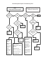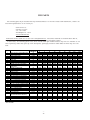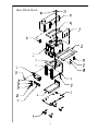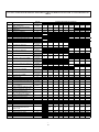
1
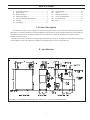
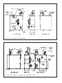
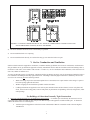
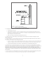
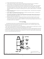
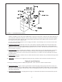
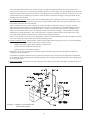
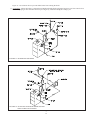
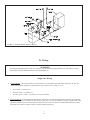
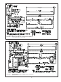
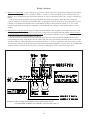
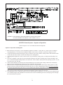
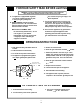
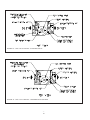
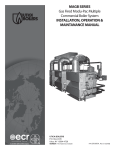
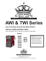
D E S I G N E D T O L E A D AWI & TWI Series Gas-Fired Natural Draft Hot Water Boilers INSTALLATION INSTRUCTIONS These instructions must be affixed on or adjacent to the boiler Models: • AWI037 • AWI061 • AWI095 • AWI128 • AWI162 • AWI195 • AWI229 • AWI262 • AWI295 • TWI061 • TWI095 • TWI128 • TWI162 WARNING: Improper installation, adjustment, alteration, service or maintenance can cause property damage, injury, or loss of life. For assistance or additional information, consult a qualified installer, service agency or the gas supplier. Read these instructions carefully before installing. Manufacturer of Hydronic Heating Products P.O. Box 14818 3633 I. Street Philadelphia, 1 PA 19134 7HO)D[ZZZFURZQERLOHUFRP 2 Table of Contents I. Product Description .................................................. 1 II. Specifications ............................................................ 1 III. Before Installing ........................................................ 4 IV. Locating the Boiler .................................................... 4 V. Air for Combustion & Ventilation ............................. 5 VI. Venting ...................................................................... 8 VII. Gas Piping ............................................................... 11 VIII. IX. X. XI. XII. XIII. System Piping ............................................. 12 Wiring ......................................................... 16 Start-Up & Checkout .................................. 21 Service & Maintenance ............................... 27 Troubleshooting .......................................... 29 Parts ............................................................ 34 I Product Description The AWI series boiler is a cast iron gas fired water boiler designed for use in closed forced circulation heating systems. This boiler is a Category I draft diverter equipped appliance, which must be vented by natural draft using a lined masonry or listed metal chimney system. An adequate supply of air for combustion, ventilation and dilution of flue gases must be available in the boiler room. The TWI series boiler is identical to corresponding sized AWI boiler except for the addition of baffles in the flue passages to obtain higher AFUEs. The TWI is not available with a standing pilot or for use with propane gas. II Specifications FIGURE 1A: STANDARD CONFIGURATION (SEE PAGE 3 FOR LETTER DIMENSIONS) 31 FIGURE 1B: “LEFT PIPED” CONFIGURATION FIGURE 1C: “TOP PIPED” (T-AWI OR T-TWI) CONFIGURATION 42 TABLE 1: SPECIFICATIONS RATINGS - NATURAL AND LP GASES* BASIC BOILER MODEL NUMBER OF SECTIONS DIMENSIONS (INCHES) DOE HEATING CAPACITY I=B=R NET RATING, WATER AFUE MBH MBH MBH % INPUT "A" "B" "C" "D" "E" "F" AWI037S AWI037E 2 37 30 26 80.0 82.3 10-1/2 7-1/4 4 3-5/8 3-7/8 AWI061S AWI061E 3 61 50 43 80.0 82.6 11-3/4 5-7/8 4 3-5/8 1-7/8 AWI095S AWI095E 4 95 78 68 80.1 82.3 15 7-1/2 5 4-1/8 1-7/8 AWI128S AWI128E 5 128 105 91 80.2 82.0 18-1/4 9-1/8 6 4-5/8 1-7/8 AWI162S AWI162E 6 162 132 115 80.3 81.7 21-1/2 10-3/4 6 4-5/8 1-7/8 AWI195S AWI195E 7 195 159 138 80.4 81.4 24-3/4 12-3/8 7 5-1/8 1-7/8 AWI229S AWI229E 8 229 186 162 80.4 81.2 28 14 7 5-1/8 1-7/8 31-1/4 15-5/8 8 5-5/8 1-7/8 34-1/2 17-1/4 8 5-5/8 1-7/8 27-7/8 29-7/8 AWI262S AWI262E 9 262 212 184 80.5 80.9 AWI295S AWI295E 10 295 238 207 80.7 80.6 RATINGS - NATURAL GAS ONLY BASIC BOILER MODEL NUMBER OF SECTIONS DIMENSIONS (INCHES) DOE HEATING CAPACITY I=B=R NET RATING, WATER AFUE MBH MBH MBH % INPUT "A" TWI061E 3 61 51 44 83.0 11-3/4 TWI095E 4 95 79 69 83.0 15 "B" "C" "D" "E" "F" 5-7/8 4 3-5/8 1-7/8 7-1/2 5 4-1/8 1-7/8 27-7/8 TWI128E 5 128 106 92 83.0 18-1/4 9-1/8 6 4-5/8 1-7/8 TWI162E 6 162 134 117 83.0 21-1/2 10-3/4 6 4-5/8 1-7/8 Notes: Suffix E = Intermittent Ignition, Suffix S = Standing Pilot Add Suffix N for Natural Gas or Suffix L for Propane Gas to basic AWI Boiler Model shown (Example: AWI295EN, AWI229SL) 53 III Before Installing 1) Safe, reliable operation of this boiler depends upon installation by a professional heating contractor in strict accordance with this manual and the requirements of the authority having jurisdiction. • In the absence of an authority having jurisdiction, installation must be in accordance with this manual and the National Fuel Gas Code, ANSI Z223.1-latest edition. • Where required by the authority having jurisdiction, this installation must conform to the Standard for Controls and Safety Devices for Automatically Fired Boilers (ANSI/ASME CSD-1)-latest edition. 2) Make sure that a properly sized chimney is available which is in good condition. Consult the authority having jurisdiction, Part VI of this manual, and the National Fuel Gas Code for additional information on venting requirements. 3) Make sure that the boiler is correctly sized: • • • • For heating systems employing convection radiation (baseboard or radiators) use an industry accepted sizing method such as the I=B=R Heat Loss Calculation Guide (Pub. #H21 or #H22) published by the Hydronics Institute in Berkeley Heights NJ. For new radiant heating systems refer to the radiant tubing manufacturer’s boiler sizing guidelines. For systems including a Crown Mega-Stor indirect water heater, size the boiler to have either the DOE Heating Capacity required for the Mega-Stor or the net rating required for the heating system, whichever results in the larger boiler. For systems that incorporate other indirect water heaters, refer to the indirect water heater manufacturer’s instructions for boiler output requirements. 4) Make sure that the boiler received is configured for the correct gas (natural or LP). 5) Boilers built for installations at altitudes above 2000 ft. require different burners and main burner orifice. Make sure that the boiler is configured for use at the correct altitude. IV Locating the Boiler 1) Clearances: • Observe the minimum clearances shown below. These clearances apply to all combustible construction, as well as noncombustible walls, ceilings and doors. Also see Figure 2. Front – 18” Left Side – 6” Right Side – 6” Rear – 6” Top – 18” • • A 24” service clearance from the jacket is recommended on the left, right, and front of the boiler. These clearances may be reduced to those shown in Figure 2, however servicing the boiler will become increasingly difficult as these service clearances are reduced. If the right side 24” service clearance is reduced, adequate clearance must be maintained to easily read both the gauge and the limit control. Alternatively, access to the gauge and limit may be provided using a door. 2) The boiler must be installed on a hard level surface. This surface may be combustible. 3) Do not install this boiler in a location where gasoline or other flammable vapors or liquids will be stored or used. Do not install this boiler in an area where large amounts of airborne dust will be present, such as a workshop. 64 FIGURE 2: CLEARANCE FROM BOILER TO ALL TYPES OF COMBUSTIBLE CONSTRUCTION AND NONCOMBUSTIBLE CEILINGS, WALLS AND DOORS 4) The boiler should be located as close to the chimney as possible. 5) Do not install this boiler over carpeting. 6) Do not install this boiler directly on a surface that may get wet. Raise the boiler on a pad. V Air for Combustion and Ventilation Sufficient fresh air must be supplied for combustion, ventilation and flue gas dilution. Provisions for combustion, ventilation and flue gas dilution air for gas utilization equipment vented by natural draft must be made in accordance with local building codes or, in absence of such codes, in accordance with sections 5.3.3 and 5.3.4 (“Air for Combustion and Ventilation”) of the National Fuel Gas Code, NFPA 54/ANSI Z 223.1. To ensure an adequate supply of combustion, ventilation and flue gas dilution air supply, start by determining whether the boiler is to be installed in a building of unusually tight construction. A building of unusually tight construction is defined by the National Fuel Gas Code as having all of the following features: • Walls and ceilings exposed to outside atmosphere have a continuous water vapor retarder with a rating of 1 perm or less with openings gasketed and sealed • • Weather stripping has been added on openable windows and doors Caulking and sealants are applied to areas such as joints around window and door frames, between sole plates and floors, between wall-ceiling joints, between wall panels, at penetrations for plumbing, electrical, and gas lines, and at other openings. For Buildings of Other than Unusually Tight Construction 1) Determine whether the boiler is to be installed in a confined space - A confined space is defined by the National Fuel Gas Code as having a volume less than 50 cubic feet per 1000 BTU/hr input of all appliances installed in that space. To determine whether the boiler room is a confined space: a. Total the input of all appliances in the boiler room in thousands of BTU/hr. Round the result to the next highest 1000 BTU/hr. 75 b. c. Find the volume of the room in cubic feet. The volume of the room in cubic feet is: Length (ft) x width (ft) x ceiling height (ft) In calculating the volume of the boiler room, consider the volume of adjoining spaces only if no doors are installed between them. If doors are installed between the boiler room and an adjoining space, do not consider the volume of the adjoining space, even if the door is normally left open. Divide the volume of the boiler room by the input in thousands of BTU/hr. If the result is less than 50, the boiler room is a confined space. Example: An AWI162EN and a water heater are to be installed in a room measuring 6 ft - 3 in x 7 ft with an 8 ft ceiling. The water heater has an input of 30000 BTU/hr: Total input in thousands of BTU/hr = (162000 BTU/hr + 30000 BTU/hr)/1000 = 192 Volume of room = 6.25 ft x 7 ft x 8 ft = 350 ft3 350/192 = 1.82. Since 1.82 is less than 50, the boiler room is a confined space. 2) Unconfined Space - Natural infiltration into the boiler room will normally provide adequate air for combustion and ventilation without additional louvers or openings into boiler room. 3) Confined Space - Provide two openings into the boiler room, one near the floor and one near the ceiling. The top edge of the upper opening must be within 12” of the ceiling and the bottom edge of the lower opening must be within 12” of the floor (Figure 3). • Each opening must have a free area of 1 square inch per 1000 BTU/hr input of all gas burning appliances in the boiler room. The minimum opening dimension is 3 inches. Minimum opening free area is 100 square inches per opening. • If the total volume of both the boiler room and the room to which the openings connect is less than 50 cubic feet per 1000 BTU/hr of total appliance input, install a pair of identical openings into a third room. Connect additional rooms with openings until the total volume of all rooms is at least 50 cubic feet per 1000 BTU/hr of input. • The “free area” of an opening takes into account the blocking effect of mesh, grills, and louvers. Where screens are used, they must be no finer than ¼” (4 x 4) mesh. • If providing openings into adjacent rooms is undesirable, combustion and ventilation air can be brought into the boiler room from outdoors. See the instructions under “For Buildings of Unusually Tight Construction”. FIGURE 3: BOILER INSTALLED IN CONFINED SPACE, ALL AIR FROM INSIDE 86 For Buildings of Unusually Tight Construction 1) Openings must be installed between the boiler room and the outdoors or a ventilated space, such as an attic or crawl space, which communicates directly with the outdoors. 2) Two openings are required. The top edge of the upper opening must be within 12 inches of the ceiling. The bottom edge of the lower opening must be within 12 inches of the floor. 3) Size openings and ducts as follows: • Vertical ducts or openings directly outdoors (Figure 4, Figure 5, and Figure 6) - Each opening must have a free cross sectional area of 1 square inch per 4000 BTU/hr of the total input of all gas-fired appliances in the boiler room but not less than 100 square inches. Minimum opening size is 3 inches. • Openings to outdoors via horizontal ducts (Figure 7) - Each opening must have a free cross sectional area of 1 square inch per 2000 BTU/hr of the total input of all gas fired appliances in the boiler room but not less than 100 square inches. Minimum opening size is 3 inches. • The “free area” of an opening takes into account the blocking effect of mesh, grills, and louvers. Where screens are used, they must be no finer than ¼” (4 x 4) mesh. FIGURE 4: ALL AIR FROM OUTDOORS, VENTILATED CRAWL SPACE AND ATTIC FIGURE 5: ALL AIR FROM OUTDOORS, VIA VENTILATED ATTIC 97 FIGURE 6: ALL AIR FROM OUTDOORS, USING OPENINGS INTO BOILER ROOM FIGURE 7: ALL AIR FROM OUTDOORS, USING HORIZONTAL DUCTS INTO BOILER ROOM VI Venting Vent installation must be in accordance with local building codes, or the local authority having jurisdiction, or Chapters 7 and 10 of the National Fuel Gas Code, NFPA 54/ANSI Z 223.1. Typical vent installation is illustrated by Figure 8. The components of vent installation are boiler draft diverter, vent damper, vent connector and chimney. The AWI and TWI series boilers are equipped with a draft diverter which is built into the boiler; do not attempt to install an external draft hood. 1) Acceptable Chimneys - The following chimneys may be used to vent AWI or TWI series boilers: • Listed Type B or L gas vent - Install in accordance with the manufacturer’s instructions, the terms of its listing, and applicable codes. • Masonry Chimney - The masonry chimney must be constructed in accordance with the Standard for Chimneys, Fireplaces, Vents, and Solid Fuel Burning Appliances (NFPA 211) and lined with a clay liner or other listed lining system. Do not vent an AWI or TWI series boiler into an unlined chimney. 10 8 FIGURE 8: TYPICAL VENT SYSTEM INSTALLATION AND COMPONENTS 2) Acceptable Vent Connectors - The following may be used for vent connectors: • Listed type B or L Gas Vent • Single Wall Galvanized Pipe - Use 0.018” (26 gauge or heavier). The size and location of the chimney may not permit the use of a single wall connector in some cases. See Chapter 10 of the National Fuel Gas Code. Do not use single wall pipe for vent connectors in attics. • Other Vent Connectors Permitted by the National Fuel Gas Code. 3) Chimney and Vent Connector Sizing - Size the chimney and vent connector in accordance with Chapter 10 of the National Fuel Gas Code. 4) Exterior Chimneys - An exterior chimney has one or more sides exposed to the outdoors below the roof line. There are two conditions under which an exterior chimney may be used: • In some very restrictive cases, the AWI and TWI series boilers may be vented into an exterior ceramic lined masonry chimney. See Chapter 10 of the National Fuel Gas Code for information on when exterior chimneys may be used. • An exterior masonry chimney may be used if it is lined with B vent or a listed chimney lining system. 5) This boiler may be vented using a listed power venter. The power venter must be in sized and installed in accordance with the power venter manufacturer’s instructions, the terms of the power venter listing, and applicable codes. The boiler must be electrically interlocked with the power venter to prevent boiler operation if the power venter fails to operate. Before deciding to use a power venter, make certain that the flue gas exiting the power venter will not damage adjacent construction or other structures. Also make certain that the power venter terminal will not be subjected to winds which could effect power venter operation. 6) Do not connect the vent of this appliance into any portion of a mechanical vent system operating under positive pressure. 7) Do not connect the boiler into a chimney flue serving an open fireplace or other solid fuel appliance. 11 9 8) Prior to boiler installation, inspect chimney for obstructions or other defects and correct as required. Clean chimney as necessary. 9) Vent pipe should slope upward from draft diverter not less than one inch in four feet. No portion of vent pipe should run downward or have sags. Vent pipe must be securely supported. 10) The vertical section of vent pipe coming off the boiler should be as tall as possible, while still maintaining the proper clearance from the horizontal vent connector to combustibles and the proper pitch called for in (9) above. 11) Vent pipe should be installed above the bottom of the chimney to prevent blockage. 12) Vent pipe must be inserted flush with inside face of the chimney liner and the space between vent pipe and chimney sealed tight. 13) Do not install the vent damper in any portion of the vent system which is used by appliances other than the boiler being installed. 14) Vent damper installation is mandatory on all AWI/TWI boiler models due to federally mandated efficiency regulations. Install vent damper (see Figure 9) as follows: a) Open vent damper carton and remove installation instructions. Read the instructions thoroughly before proceeding. Verify that vent damper is same size as draft diverter outlet. See Figure 1. Unpack vent damper carefully. Do not force closed damper blade. Forcing vent damper closed may result in damaged gear train and void warranty. b) Vent damper is factory shipped having approximately ¾” diameter hole in the vent damper blade, which must be left open for boilers equipped with standing pilot, and should be plugged on boilers with EI control system, using the plug supplied with the damper. Mount the vent damper on the flue collar without modification to either and secure with sheet metal screws. Make sure screws do not interfere with damper blade operation. Vent damper blade position indicator must be visible to users. c) The damper wire harness is shipped wired into the boiler limit control. Plug the loose end of this harness into the damper and secure the flexible conduit to the damper using a connector nut provided. Provide adequate clearance to combustible construction and servicing. d) Install vent connector pipe and vent fittings from vent damper outlet to chimney or gas vent. Secure with sheet metal screws and support as required. RIGHT SIDE VIEW FIGURE 9: VENT DAMPER INSTALLATION DETAILS Removing an Existing Boiler from a Common Chimney In some cases, when an existing boiler is removed from a common chimney, the common venting system may be too large for the remaining appliances. At the time of removal of an existing boiler the following steps shall be followed with each appliance remaining connected to the common venting system placed in operation, while the other appliances remaining connected to the common venting system are not in operation. 12 10 a) Seal any unused opening in the common venting system. b) Visually inspect the venting system for proper size and horizontal pitch and determine there is no blockage or restriction, leakage, corrosion and other deficiencies which could cause an unsafe condition. c) Insofar as practical, close all building doors and windows and all doors between the space in which all the appliances remaining connected to the common venting system are located and other spaces of the building. Turn on clothes dryers and any appliance not connected to the common venting system. Turn on any exhaust fans, such as range hoods and bathroom exhausts, so they will operate at maximum speed. Do not operate a summer exhaust fan. Close fireplace dampers. d) Place in operation the appliance being inspected. Follow the lighting instructions. Adjust thermostat so the appliance will operate continuously. e) Test for spillage at the draft hood relief opening after five (5) minutes of main burner operation. Use the flame of a match or candle, or smoke from a cigarette, cigar, or pipe. f) After it has been determined that each appliance remaining connected to the common venting system properly vents when tested as outlined above, return doors, windows, exhaust fans, fireplace dampers and any other gas-burning appliances to their previous condition of use. g) Any improper operation of the common venting system should be corrected so the installation conforms with the National Fuel Gas Code, ANSI Z223.1. When resizing any portion of the common venting system, the common venting system should be resized to approach the minimum size as determined using the appropriate tables in Part 10 of the National Fuel Gas Code, ANSI Z223.1. VII Gas Piping Gas piping to the boiler must be sized to deliver adequate gas for the boiler to fire at the nameplate input at a line pressure between the minimum and maximum values shown on the rating plate. For more information on gas line sizing, consult the utility or Part 2 of the National Fuel Gas Code. Figure 10 shows typical gas piping connection to the AWI/TWI boiler. A sediment trap must be installed upstream of all gas controls. Install a manual shut-off valve outside the jacket and ground joint union as shown. The boiler and its gas connection must be leak tested before placing the boiler in operation. When doing this, the boiler and its individual shut-off must be disconnected from the rest of the system during any pressure testing of that system at pressures in excess of 1/2 psi. When pressure testing the gas system at pressures of 1/2 psi or less, isolate the boiler from the gas supply system by closing its individual manual shut-off valve. * * State of Massachusetts Requires Manual Shut-off Valve to be “T” Handle Type FIGURE 10: GAS CONNECTION TO BOILER 13 11 VIII System Piping CAUTION • INSTALL BOILER SO THAT THE GAS IGNITION SYSTEM COMPONENTS ARE PROTECTED FROM WATER (DRIPPING, SPRAYING, RAIN, ETC.) DURING APPLIANCE OPERATION AND SERVICE (CIRCULATOR REPLACEMENT, ETC.). • OPERATION OF THIS BOILER WITH CONTINUOUS RETURN TEMPERATURES BELOW 120°F CAN CAUSE SEVERE HEAT EXCHANGER CORROSION DAMAGE. • OPERATION OF THIS BOILER IN A SYSTEM HAVING SIGNIFICANT AMOUNTS OF DISSOLVED OXYGEN CAN CAUSE SEVERE HEAT EXCHANGER CORROSION DAMAGE. • DO NOT USE TOXIC ADDITIVES, SUCH AS AUTOMOTIVE ANTIFREEZE, IN A HYDRONIC SYSTEM. Standard Piping Figure 11 shows typical boiler system connections on a single zone system. Additional information on hydronic system design may be found in Installation of Residential Hydronic Systems (Pub. #200) published by the Hydronics Institute in Berkeley Heights, NJ. The components in this system and their purposes are as follows: 1) Relief valve (Required) - Mount the relief valve on the right side of the boiler as shown in Figure 1 using the 3/4 nipples and elbow provided. The relief valve shipped with the boiler is set to open at 30 psi. This valve may be replaced with one having a pressure up to the “Maximum Allowable Working Pressure” shown on the rating plate If the valve is replaced, the replacement must have a relief capacity in excess of the DOE heating capacity for the boiler. Pipe the discharge of the relief valve to a location where water or steam will not create a hazard or cause property damage if the valve opens. The end of the discharge pipe must terminate in an unthreaded pipe. If the relief valve discharge is not piped to a drain it must terminate at least 6 inches above the floor. Do not run relief valve discharge piping through an area that is prone to freezing. The termination of the relief valve discharge piping must be in an area where it is not likely to become plugged by debris. DANGER • • • • PIPE RELIEF VALVE DISCHARGE TO A SAFE LOCATION. DO NOT INSTALL A VALVE IN THE RELIEF VALVE DISCHARGE LINE. DO NOT MOVE RELIEF VALVE FROM FACTORY LOCATION. DO NOT PLUG RELIEF VALVE DISCHARGE. 2) Circulator (Required) - Although the circulator is shipped on the boiler return, it can be installed on the boiler supply. If the circulator is moved to the supply it should be positioned just downstream of the expansion tank as shown in Figure 11. 3) Expansion Tank (Required) - If this boiler is replacing an existing boiler with no other changes in the system, the old expansion tank can generally be reused. If the expansion tank must be replaced, consult the expansion tank manufacturer’s literature for proper sizing. 4) Fill Valve (Required) - Either a manual or automatic fill valve may be used. The ideal location for the fill is at the expansion tank. 5) Automatic Air Vent (Required) - At least one automatic air vent is required. Manual vents will usually be required in other parts of the system to remove air during initial fill. 6) Low Water Cut-Off (Required in some situations) - A low water cutoff is required when the boiler is installed above 14 12 FIGURE 11: STANDARD BOILER PIPING radiation. In addition, some codes such as ASME CSD-1 require low water cutoffs. Codes may also require that this low water cutoff have a manual reset function. The low water cutoff may be a float type or probe type, but must be designed for use in a hot-water system. The low water cutoff should be piped into the boiler supply just above the boiler with no intervening valves between it and the boiler. Use a low water cutoff that breaks the 120 VAC supply to the boiler. Do not attempt to wire a 24-volt low water cutoff into the boiler factory wiring. 7) Manual Reset High Limit (Required by some codes) - This control is required by ASME CSD-1 and some other codes. Install the high limit in the boiler supply piping just beyond the boiler with no intervening valves. Set the manual reset high limit as far above the operating limit setting as possible, but not over 240°F. Wire the control to break the 120 VAC electrical supply to the boiler. 8) Flow Control Valve (Required under some conditions) - The flow control valve prevents flow through the system unless the circulator is operating. A flow control valve may be necessary on converted gravity systems to prevent gravity circulation. Flow control valves are also used to prevent “ghost flows” in circulator zone systems through zones that are not calling for heat. 9) Isolation Valves (Optional) - Isolation valves are useful if the boiler must be drained, as they will eliminate having to drain and refill the entire system. 10) Drain Valve - The drain valve is shipped in the boiler parts bag. Install it in the tee under the circulator as shown in Figure 1. Piping for Special Situations Certain types of heating systems have additional requirements. Some of the more common variations follow: 1) Indirect Water Heaters - Figure 12 shows typical indirect water heater piping. Boiler piping is the same as for any twozone system. Figure 12 shows circulator zoning, which is usually preferred for indirect water heaters. Size the circulator and indirect water heater piping to obtain the boiler water flow through the indirect water heater called for by the indirect water heater manufacturer. 2) Large Water Volume Systems - The piping shown in Figure 13 will minimize the amount of time that the boiler operates 15 13 with return temperatures below 120°F on these systems. A bypass is installed as shown to divert some supply water directly into the return water. The bypass pipe should be the same size as the supply. The two throttling valves shown are adjusted so that the return temperature rises above 120°F during the first few minutes of operation. A three-way valve can be substituted for the two throttling valves shown. If the circulator is mounted on the supply, the bypass must be on the discharge side of the circulator. 3) Low Temperature Systems - Some systems, such as radiant tubing systems, require the system water temperature to be limited to a value below the temperature of the water leaving the AWI or TWI. These systems also typically have return temperatures well below the 120°F minimum. Figure 14 illustrates the use of a heat exchanger to connect the AWI or TWI boiler to this type of system. The heat exchanger will permit the transfer of heat from the boiler water to the low temperature system while holding the system supply and boiler return temperatures within their limits. For this system to work properly the heat exchanger must be properly sized and the correct flow rates are required on either side of the heat exchanger. Consult the heat exchanger manufacturer for sizing information. The water in the boiler is completely isolated from the water in the system. This means that separate fill and expansion tanks are required for the heating system loop. There are several other ways to connect low temperature systems to the non-condensing boilers like the AWI or TWI such as four way mixing valve and variable speed injection pumping systems. 4) Systems containing oxygen - Many hydronic systems contain enough dissolved oxygen to cause severe corrosion damage to a cast iron boiler such as the AWI or TWI. Some examples include: • Radiant systems that employ tubing without an oxygen barrier. • Systems with routine additions of fresh water. • Systems which are open to the atmosphere. If the boiler is to be used in such a system, it must be separated from the oxygenated water being heated with a heat exchanger as shown in Figure 14. Consult the heat exchanger manufacturer for proper heat exchanger sizing as well as flow and temperature requirements. All components on the oxygenated side of the heat exchanger, such as the pump and expansion tank, must be designed for use in oxygenated water. 5) Piping with a Chiller - If the boiler is used in conjunction with a chiller, pipe the boiler and chiller in parallel as shown in FIGURE 12: INDIRECT WATER HEATER BOILER SIDE PIPING 16 14 Figure 15. Use isolation valves to prevent chilled water from entering the boiler. 6) Air Handlers - Where the boiler is connected to air handlers through which refrigerated air passes, use flow control valves in the boiler piping or other automatic means to prevent gravity circulation during the cooling cycle. FIGURE 13: BOILER BYPASS PIPING FIGURE 14: ISOLATION OF BOILER FROM SYSTEM WITH A HEAT EXCHANGER 17 15 FIGURE 15: BOILER PIPING WITH CHILLER IX Wiring WARNING All wiring and grounding must be done in accordance with the authority having jurisdiction or, in the absence of such requirements, with the National Electrical Code (ANSI/NFPA 70) Single Zone Wiring 1) 120 Volt Wiring - The boiler should be provided with its own 15A branch circuit with fused disconnect. All 120 volt connections are made inside the L8148E aquastat relay as follows (also see Fig. 16 or 17): • • • Hot (“black”) - Terminal “L1” Neutral (“white”) - Terminal “L2” Ground (“green” or bare) - Ground screw on case of L8148E 2) Thermostat Wiring - Follow thermostat manufacturer instructions. To insure proper thermostat operation, avoid installation in areas of poor air circulation, hot spots (near any heat source or in direct sunlight), cold spots (outside walls, walls adjacent to unheated areas, locations subject to drafts). Provide Class II circuit between thermostat and boiler. Connect thermostat wire leads to terminals T and TV inside L8148E aquastat relay. 18 16 2 FIGURE 16: WIRING DIAGRAM, CONTINUOUS IGNITION (STANDING PILOT) SYSTEM 2 FIGURE 17: WIRING DIAGRAM, INTERMITTENT IGNITION (EI) SYSTEM 19 17 Wiring Variations 1 ) Multiple Circulator Zones – Figure 18 shows wiring for two or more circulator zones using Honeywell R845As. One R845A is required for each circulator zone. Circulator terminals “C1” and “C2” on the L8148E are not used. A DPST Honeywell RA832A may be substituted in place of the R845A using the “X” and “X” terminals in place of the “5” and “6” terminals on a R845A. A call for heat from any thermostat will energize the DPST relay in that zone’s R845A. When this relay is energized, electrical continuity is created between terminals 3 and 4, energizing the circulator for that zone. At the same time, electrical continuity is created between terminals 5 and 6 on the R845A, creating a current path from terminal “T” to “TV” on the L8148E. Assuming that the supply water temperature is below the high limit setting, the normal ignition sequence will be initiated. 2) Multiple Zones using Zone Valves – Figure 19 shows wiring for multiple zones using Honeywell V8043F zone valves. This wiring diagram may be used for other 24-volt zone valves as long as they are equipped with end switches. Do not attempt to use the transformer on the L8148E to power the zone valves; use a separate transformer. Up to five V8043Fs may be powered by one 48VA transformer, such as the Honeywell AT87A. A call for heat from a given thermostat will result in the application of 24 volts across the TH and TR terminals on the corresponding zone valve, energizing the zone valve motor. The zone valve opens and the end switch contacts are then made. The end switches are connected in parallel with each other and to the “T” and “TV” thermostat connections so that any zone valve that opens will also start the circulator and fire the boiler (assuming the high limit is not open). Zone valve terminal TH/ TR has no internal connection on the zone valve; it is merely a “binding post” used to connect two or more wires. FIGURE 18: CIRCULATOR ZONE WIRING USING HONEYWELL R845As (FACTORY BOILER WIRING NOT SHOWN - SEE FIGURE 16 OR 17) 20 18 FIGURE 19: ZONE WIRING USING HONEYWELL V8043F ZONE VALVES (FACTORY WIRING NOT SHOWN - SEE FIGURE 16 OR 17) AWI/TWI Control System – Sequence of Operation (Refer to Figures 16 or 17 for ladder and connection diagrams) Sequence of Operation, Standing Pilot 1) When the boiler is energized, 24 volts is immediately applied to terminals “1” (blue) and “4” (yellow) on the vent damper. Assuming that there is no call for heat, and that the damper switch is in the “automatic” position, the damper will close. 2) A call for heat from the thermostat energizes relay coil 1R (the relay on the L8148E), causing contacts 1R1 and 1R2 to make. Contact 1R1 starts the circulator. Contact 1R2 sends power to the high limit. 3) Assuming that the high limit is made, current will flow to pin terminal #2 (orange) at the vent damper and the damper will open. 4) Once the vent damper is fully open, an end switch inside the damper will make, energizing pin #3 (red) at the damper. This pin is connected through the damper harness to terminal “B1” on the L8148E. At this point in the operating sequence, 24 volts is present across “B1” and “B2”. 5) Under normal conditions, the flame roll-out switch and blocked vent switch are made. Voltage will therefore immediately appear across the combination gas control (“gas valve”) terminals “TH” and “TR”. 6) When the boiler is first placed into operation, the pilot must be lit. The pilot heats a thermocouple which generates a small amount of electricity sufficient to hold open the safety shut-off valve in the combination gas control. The circuit connecting the thermocouple and the safety shut-off valve is self contained and completely independent of all other wiring on the boiler. This safety shut-off valve is upstream of the 24 volt valves in the gas control which open in response to a call for heat. If the pilot is not lit, the safety shut-off valve will remain closed and gas will not reach the 24 volt valves. 7) Assuming that the pilot is established and proven by the thermocouple, the application of 24 volts across the combination gas valve terminals energizes the redundant 24 volt solenoid valves in the combination gas control, resulting in gas flow through the control and burner operation. 21 19 Sequence of Operation, Intermittent Ignition 1) When the boiler is energized, 24 volts is immediately applied to terminals “1” (blue) and “4” (yellow) on the vent damper. Assuming that there is no call for heat, and that the damper switch is in the “automatic” position, the damper will close. 2) A call for heat from the thermostat energizes relay coil 1R (the relay on the L8148E), causing contacts 1R1 and 1R2 to make. Contact 1R1 starts the circulator. Contact 1R2 sends power to the high limit. 3) Assuming that the high limit is made, current will flow to pin terminal #2 (orange) at the vent damper and the damper will open. 4) Once the vent damper is fully open, an end switch inside the damper will make, energizing pin #3 (red) at the damper. This pin is connected through the damper harness to terminal “B1” on the L8148E. At this point in the operating sequence, 24 volts is present across “B1” and “B2”. 5) Under normal conditions, the flame roll-out switch and blocked vent switch are made. Voltage will therefore immediately appear across the “24V” and “24V (GND)” terminals on the ignition module. 6) Upon application of voltage across the “24V” and “24V (GND)” terminals, the ignition module will start an ignition spark at the pilot and apply 24 volts across the pilot valve (terminals “PV” and “MV/PV”). 7) Once the pilot is established, the pilot flame will act as a diode, converting the AC current at the electrode to a half wave DC current at the pilot’s ground strap. This DC current flows through the boiler to the “GND (BURNER)” connection on the ignition module. For the ignition module to recognize that a pilot flame is present, the DC current flowing into this terminal must be in excess of approximately 1.0 uA. 8) Once the ignition module detects the presence of a pilot flame, voltage is applied across the main valve (terminals “MV” and “MV/PV”), opening the valve and establishing main flame. 9) The way in which the ignition module handles failure to establish pilot or the loss of an already established pilot depends upon the exact ignition module supplied with the boiler. For more information on module operation, consult the ignition module instructions supplied with the boiler or the local Crown representative. Safety Control Operation - Standing Pilot and Intermittent Ignition High Limit - Interrupts main burner operation when the supply water temperature exceeds set point. Maximum allowable temperature is 250°F. If the high limit opens, the vent damper will close if the damper switch is in the “automatic” position. The circulator will continue to operate as long as there is a call for heat, regardless of the status of the high limit. Burner operation automatically resumes when the supply water temperature falls below set point. Blocked Vent (“Spill”) Switch - Automatically interrupts main burner operation in the event that flue gas spills from the draft diverter opening. This switch is equipped with a reset button which must be pressed to restore normal burner operation. An open blocked vent switch is indicative of a problem with the vent system. If the blocked vent switch opens, the cause of the venting problem must be found and corrected by a qualified gas service technician before the blocked vent switch is reset. Flame Roll-out Switch - Automatically interrupts boiler operation when flames or excessive heat are present in vestibule. The flame roll-out switch is a single use device which must be replaced by an identical switch in order to restore normal operation. An open flame roll-out switch is usually indicative of a plugged heat exchanger. The cause of the flame roll-out must be found and corrected by a qualified gas service technician, and the switch replaced with an identical one, before the boiler is returned to operation. 22 20 X Start-up and Checkout NOTE SAFE LIGHTING AND OTHER PERFORMANCE CRITERIA WERE MET WITH THE GAS MANIFOLD AND CONTROL ASSEMBLY PROVIDED ON THE BOILER WHEN THE BOILER UNDERWENT THE TESTS SPECIFIED IN Z21.13. Use the following procedure for initial start-up of the boiler: 1) Make sure that the boiler and system are filled with water. 2) Check all new gas piping for leaks and purge piping sections that are filled with air. See Part 4 of the National Fuel Gas Code for additional information on testing and purging gas lines. WARNING • • NEVER USE A FLAME TO CHECK FOR GAS LEAKS. MAKE SURE THAT THE AREA AROUND THE BOILER IS CLEAR AND FREE FROM COMBUSTIBLE MATERIALS, GASOLINE, AND OTHER FLAMMABLE VAPORS AND LIQUIDS. 3) Verify that vent system is complete and free of obstructions before attempting to fire boiler. 4) Inspect all wiring for loose or uninsulated connections. 5) Make sure the main burners are seated properly in the rear of burner tray and on orifices. 6) Adjust thermostat to the highest setting. 7) Start the boiler using the lighting instructions for boilers with standing pilot (page 24) or operating instructions for boilers with intermittent ignition (page 25). 8) Upon initial start-up, the gas train will be filled with air. Even if the gas line has been completely purged of air, it may take several tries for ignition before a flame is established. Once a flame has been established for the first time, subsequent calls for burner operation should result in a flame on the first try. 9) Observe pilot burner flame: • See Figure 20 for standing pilot. Pilot burner should produce single steady medium blue flame covering around 3/ 8” to ½” of thermocouple tip. • See Figure 21 for intermittent ignition. Pilot burner produces three flames. The center one should be a steady medium blue flame covering around 3/8” to ½” of spark electrode/flame rod. 10) Make sure vent damper is in open position when main burners are firing. 11) Inspect the main burner flames visible through the observation port in burner access panel. The flame should be stable and mostly blue (see Figure 22 or 23). No yellow tipping should be present; however, intermittent flecks of yellow and orange in the flame are normal. 12) Check entire gas train for leaks using soap and water or other approved leak detection method while boiler is firing. Fix any leaks found immediately. 23 21 13) Run gas valve safety shutdown test: • For standing pilot boiler models, disconnect the thermocouple from gas valve. Both pilot burner and main burners should stop firing. • For intermittent ignition boiler models, with main burners firing, disconnect ignition cable from ignition module. Both pilot burner and main burners should stop firing. 14) Check the manifold pressure and adjust if necessary. To do this, use the following procedure: WARNING FAILURE TO FOLLOW THE FOLLOWING PROCEDURE EXACTLY COULD RESULT IN OVERFIRING OF THE BOILER AND A CARBON MONOXIDE HAZARD. a) Connect a manometer to the line pressure tap on the gas valve (see Figures 24 and 25). b) Check the line pressure with all gas appliances on and off. The line pressure at the boiler must be within the following limits regardless of what combination of appliances is firing: Line Press (inches w.c.) Natural Gas LP Gas Min. 5.0 11.0 Max. 14.0 13.0 If the line pressure falls outside of these limits, find and correct the cause of the problem before proceeding further. c) Connect a manometer to the manifold (outlet) pressure tap on the gas valve (see Figures 24 and 25). d) Read the manifold pressure. It should be set at: Natural Gas Manifold Press. (inches w.c.) e) 3.5 LP Gas 10.0 If a manifold pressure adjustment is needed, make the adjustment by turning the regulator (see Figures 24 and 25) screw clockwise to raise the pressure and counter clockwise to reduce the pressure. If a manifold pressure adjustment is made, recheck the line pressure to be certain that it is still within acceptable limits. Replace the cover screw on the regulator. 15) Test thermostat operation while the boiler is running. Turn the thermostat to the lowest setting. Circulator should stop running. For standing pilot boiler models, pilot burner should remain lit but the main burners should stop firing. For intermittent ignition boiler models both pilot burner and main burners should stop firing. Raise the thermostat back to the highest setting. Circulator should restart. The main burners( for standing pilot boiler models) or pilot burner and main burners (for intermittent ignition boiler models) should relight. 16) Verify high limit operation. Allow the boiler water temperature to increase to hi limit setting. Circulator should continue running. For standing pilot boiler models, pilot burner should remain lit but the main burners should stop firing. For intermittent ignition boiler models both pilot burner and main burners should stop firing. 17) Allow the boiler water temperature to drop below high limit setting. 18) The main burners (for standing pilot boiler models) or pilot burner and main burners (for intermittent ignition boiler models) should relight. 24 22 19) After the boiler has operated for approximately 30 minutes, check the boiler and heating system piping for leaks. Repair any leaks found at once. 20) Inspect the vent system for flue gas leaks. Repair any leaks found before leaving the boiler in operation. FIGURE 21: INTERMITTENT IGNITION PILOT BURNER FLAME FIGURE 20: STANDING PILOT BURNER FLAME FIGURE 23: MAIN BURNER FLAME - 50mm (“HIGH ALTITUDE”) BURNERS FIGURE 22: MAIN BURNER FLAME - 1” BURNERS 25 23 FOR YOUR SAFETY READ BEFORE OPERATING WARNING: If you do not follow these instructions exactly, a fire or explosion may result causing property damage, personal injury or loss of life. If you cannot reach your gas supplier, call the fire department. A. This appliance has a pilot which must be lighted by hand. When lighting the pilot, follow these instructions exactly. C. Use only your hand to push in or turn the gas control knob. Never use tools. If the knob will not push in or turn by hand, don’t try to repair it, call a qualified service technician. Force or attempted repair may result in a fire or explosion. B. BEFORE LIGHTING smell all around the appliance area for gas. Be sure to smell next to the floor because some gas is heavier than air and will settle on the floor. D. Do not use this appliance if any part has been under water. Immediately call a qualified service technician to inspect the appliance and to replace any part of the control system and any gas control which has been under water. WHAT TO DO IF YOU SMELL GAS Do not try to light any appliance. Do not touch any electric switch; do not use any phone in your building. Immediately call your gas supplier from a neighbor’s phone. Follow the gas supplier’s instructions. LIGHTING INSTRUCTIONS 1. STOP! Read the safety information above on this label. 8. Turn Knob on gas control counterclockwise to “PILOT”. 2. Set the thermostat to lowest setting. 9. Push down and hold the red reset button while you light pilot burner with a match. After about one minute, release reset button. Pilot should remain lit. If it goes out, turn gas control knob clockwise to OFF. To relight, repeat steps 5-9. If button does not pop up when released, stop and immediately call your service technician or gas supplier. If the pilot will not stay lit after several tries, turn the gas control knob to “OFF” and call your service technician or gas supplier. 3. Turn off all electric power to the appliance. 4. Remove front access panel. 5. Rotate the gas control knob clockwise to OFF. RESET BUTTON GAS INLET GAS OUTLET 10. After pilot remains lit when red reset button is released, turn gas control knob counterclockwise to ON. GAS CONTROL KNOB (SHOWN IN “ON” POSITION) GAS VALVE - TOP VIEW 6. Wait five (5) minutes to clear out any gas. Then smell for gas, including near the floor. If you then smell gas, STOP! Follow “B” in the safety information above on this label. If you don’t smell gas, go to the next step. 7. Find pilot - follow metal pilot tube from gas control to PILOT pilot burner. BURNER 11. Replace front access panel. 12. Turn on all electric power to the appliance. 13. Set thermostat to desired setting. THERMOCOUPLE TO TURN OFF GAS TO APPLIANCE 1. Set the thermostat to lowest setting. 3. Push in gas control knob slightly and turn clockwise to “OFF”. Do not Force. 2. Turn off all electric power to the appliance if service is to be performed. 146-80-254 Rev. 0 (Standing Pilot) 26 24 FOR YOUR SAFETY READ BEFORE LIGHTING WARNING: If you do not follow these instructions exactly, a fire or explosion may result causing property damage, personal injury or loss of life. A. This appliance is equipped with an ignition device which automatically lights the pilot. Do not try to light the pilot by hand. If you cannot reach your gas supplier, call the fire department. C. Use only your hand to push in or turn the gas control knob. Never use tools. If the knob will not push in or turn by hand, don’t try to repair it, call a qualified service technician. Force or attempted repair may result in a fire or explosion. B. BEFORE LIGHTING smell all around the appliance area for gas. Be sure to smell next to the floor because some gas is heavier than air and will settle on the floor. WHAT TO DO IF YOU SMELL GAS Do not try to light any appliance. Do not touch any electric switch; do not use any phone in your building. Immediately call your gas supplier from a neighbor’s phone. Follow the gas supplier’s instructions. D. Do not use this appliance if any part has been under water. Immediately call a qualified service technician to inspect the appliance and to replace any part of the control system and any gas control which has been under water. OPERATING INSTRUCTIONS 1. STOP! Read the safety information above on this label. 5. Remove front access panel. 6. Rotate the gas control knob clockwise 2. Set the thermostat to lowest setting. to OFF. 7. Wait five (5) minutes to clear out any gas. Then smell for gas, including near the floor. If you then smell gas, STOP! Follow “B” in the safety information above on this label. If you don’t smell gas go to the next step. 3. Turn off all electric power to the appliance. 4. This appliance is equipped with an ignition device which automatically lights the pilot. Do not try to light the pilot by hand. GAS CONTROL KNOB (SHOWN IN “ON” POSITION) 8. Rotate the gas control knob counter clockwise to “ON”. 9. Replace front access panel. 10. Turn on all electric power to the appliance. GAS INLET GAS OUTLET 11. Set thermostat to desired setting. 12. If the appliance will not operate, follow the instructions “To Turn Off Gas To Appliance” and call your service technician or gas supplier. GAS VALVE - TOP VIEW TO TURN OFF GAS TO APPLIANCE 1. Set the thermostat to lowest setting. 3. Push in gas control knob slightly and turn clockwise to “OFF”. Do not Force. 2. Turn off all electric power to the appliance if service is to be performed. 146-80-255 Rev. 0 (Electronic Ignition) 27 25 FIGURE 24: GAS VALVE DETAIL - STANDING PILOT FIGURE 25: GAS VALVE DETAIL - INTERMITTENT IGNITION 28 26 XI Service and Maintenance The following routine maintenance should be performed on an annual basis: 1) Turn off electrical power and gas supply to the boiler 2) Inspect the flue passages for signs of blockage. If there is any carbon in the combustion chamber or the flue passages, clean the heat exchanger before proceeding further. See the cleaning procedure below. 3) Remove any debris found in the combustion chamber, being careful not to disturb combustion chamber insulation. 4) Remove all burners, noting the location of the pilot main burner. If burners show signs of deterioration, they should be replaced (some discoloration around the burner ports is normal). Clean the burners by first brushing the ports with a soft bristle brush and then vacuuming out any debris through the venturi opening. 5) Inspect the pilot assembly: • • Standing Pilots - Check the thermocouple for deterioration (some discoloration of the thermocouple is normal). If any deterioration is present, replace the thermocouple. Inspect the pilot assembly for deposits and deterioration. Clean or replace the pilot assembly as necessary. Intermittent Pilots - Clean any deposits found on the electrode and grounding strap. The ideal gap between the electrode and the ground strap is 1/8”. Inspect the porcelain for cracks or other deterioration. Replace pilot assembly if deterioration is found. 6) Inspect the combustion chamber insulation for deterioration. 7) (Intermittent Pilot Boilers) - Inspect the ignition cable insulation for cracks or other deterioration. If deterioration is found, replace cable. 8) Reinstall burners, being careful to put the pilot main burner in its original location. 9) Inspect all boiler wiring for loose connections or deterioration. CAUTION LABEL ALL WIRES PRIOR TO DISCONNECTION WHEN SERVICING CONTROLS. WIRING ERRORS CAN CAUSE IMPROPER AND DANGEROUS OPERATION. VERIFY PROPER OPERATION AFTER SERVICING 10) Inspect the vent system: • • • • Make sure that the vent system is free of obstructions. Make sure that all vent system supports are intact. Inspect joints for signs of condensate or flue gas leakage. Inspect venting components for corrosion or other deterioration. Replace any defective vent components. 11) Inspect the boiler and hydronic system for leaks. CAUTION WATER LEAKS CAN CAUSE SEVERE CORROSION DAMAGE TO THE BOILER OR OTHER SYSTEM COMPONENTS. REPAIR ANY LEAKS FOUND IMMEDIATELY 12) Place the boiler back in operation using the procedure outlined in “Start-up”. Check the pilot line and any other gas piping disturbed during the inspection process for leaks. 29 27 Heat Exchanger Cleaning Procedure 1) 2) 3) 4) 5) 6) 7) 8) 9) Turn off electrical power and gas supply to the boiler Disconnect the damper and vent connector from the boiler. Remove the upper front and top jacket panels. If possible, remove the rear and left side jacket panels Remove the burners. Remove the blocked vent (“spill”) switch Remove the two ¼-20 nuts and washers holding the flue collector onto the heat exchanger. Remove the flue collector from the heat exchanger. Carefully remove the flue collector gasket strips and set them aside Clean the flue passageways using a stiff bristle brush. Be certain that all foreign material is removed from the gaps between the pins 10) Clean the bottom surfaces of the heat exchanger 11) Put a light in the combustion chamber and look through the flue passages from the top to verify that they have been thoroughly cleaned. 12) Replace the flue collector gasket strips. If desired, RTV-732 silicone sealant with a 500F intermittent duty temperature rating may be substituted for this rope gasket. The flue collector must be thoroughly sealed to the heat exchanger. 13) Replace the ¼-20 nuts and washers that hold down the flue collector 14) Reattach all the jacket components. 15) Reinstall burners, being careful to put the pilot main burner in its original location. 16) Replace the blocked vent switch. WARNING SOOT DEPOSITS IN THE FLUE PASSAGES ARE A SIGN THAT THE BOILER MAY BE OPERATING AT HIGH CARBON MONOXIDE (CO) LEVELS. AFTER CLEANING THE BOILER OF SOOT DEPOSITS, CHECK THE CO LEVEL IN THE FLUE GAS TO INSURE THAT THE BOILER IS OPERATING PROPERLY. If it is necessary to check CO, use a combustion analyzer, or other instrument which is designed to measure CO in flue gas. A CO “sniffer” designed for testing CO levels in ambient air cannot be used to check boiler combustion. Take a flue gas sample by inserting a sample probe through the draft diverter opening and into the flue collector so that the sample is taken in the area directly over the heat exchanger. Do not take a sample until the boiler has been firing for at least five minutes. A normal CO reading for an AWI or TWI series boiler is less than 50ppm (0.005%). A reading of more than 100ppm (0.01%) is indicative of a combustion problem. Some causes of excessive CO include: • • • • • • • Incorrectly sized main burner orifice for the altitude at which boiler is installed Crooked or out-of-round orifice holes (never attempt to drill orifice for this boiler in the field) Partially plugged flue passages Improper manifold pressure Foreign material in burner venturis or burner ports Leak in seal between flue collector and heat exchanger Inadequate supply of combustion air 17) Reconnect the damper and vent system. 30 28 XII Troubleshooting The following four pages contain troubleshooting charts for use in diagnosing control problems. To use these charts, go to the box marked “Start” at the top of the chart on page 30 and follow the appropriate path though the chart until a box with a list of possible causes is reached. If the problem is known to be within the ignition system, go directly to the appropriate troubleshooting guide for the boiler (standing pilot on page 32 or intermittent ignition on page 33). In using these charts, the following should be kept in mind: 1) These charts are only meant to be used by a professional heating technician as an aid in diagnosing control problems. 2) Where applicable, follow all precautions outlined in the appropriate lighting instructions on page 24 or 25. 3) In general, these charts assume that there are no loose or miswired electrical connections. Before using these charts, inspect all electrical connections on the boiler to make sure that they are tight. Also, check the wiring on the boiler against the appropriate wiring diagram in Figure 16 or 17. 4) The possible causes at the end of each branch in these charts are not listed in order of likelihood. All controls on the AWI and TWI are tested at least once in the manufacturing process and a defective control or component is generally the least likely cause. Before replacing a component, try to rule out all other possible causes. 5) These troubleshooting charts assume that the vent damper is closed at the beginning of the troubleshooting process. With the 120 volts applied to the boiler and no call for heat, the damper should go to the closed position. If it does not, do the following: • • • • • Confirm that 120 volts is applied to the boiler and that there is no call for heat. Make sure that the switch on the damper is in the “automatic” position. Unplug the harness from the damper and check for 24 volts across pin #1 (blue) and pin #4 (yellow). If voltage is present, the damper is defective or there is an obstruction in the path of the damper blade. If no voltage is present, there is either a loose connection in the damper harness or the L8148E is defective. 6) If the charts indicate that the L8148E is defective, do the following before replacing it: • • • • Check for 24 volts across TV and Z. If no voltage is present, the transformer in the L8148E is defective. It is possible that this transformer has been destroyed by a short circuit in the boiler wiring. Before replacing the control, carefully inspect all low voltage wiring on the boiler for places where it is touching the frame of the boiler or wiring on the other side of the transformer. If 24 volts is present across TV and Z, check for 24 volts between T and W. If no voltage is present, make sure that the brass jumper is present between W and Z and that the screws holding this jumper in place are both tight. If not already done, temporarily replace the thermostat across TV and T with a jumper. If the boiler fires when this is done, there is a problem with the thermostat or zone wiring. If 24 volts is present across T and W and the relay in the L8148E does not pull in, the relay in the L8148E is probably defective. Inspect the coil of this relay for visible heat damage. If such damage is found, there is a good chance that a second transformer is present in the thermostat or zone valve circuit, resulting in the application of 48 volts across the relay coil. In older buildings, this transformer may be hidden in a location far from the boiler. If this second transformer exists, it must be found and removed before the L8148E is replaced. 7) When checking voltage across damper harness pins, be careful not to insert the meter probes into the pins. Doing so may damage the pin, resulting in a loose connection when the harness is reconnected. 31 29 AWI/TWI Troubleshooting Chart START Caution: Read page 29 before attempting to use this chart Thermostat calls for heat Circulator start? Vent damper open? Y Y N N *Pow er off N *Blow n fuse or tripped breaker *Misw ired or loose electrical connection in 120V line 120 volts at L1&L2? 24 volts across B and R (limit sw itch) in L8148E ? Y 120 volts at C1&C2? 120 volts across terminals at circulator? Y N Remove t'stat or zone valve end sw itch w ires from T&TV terminals on L8148E. Install temporary jumper across terminals T and TV. Does circulator run now ? Y Y N Y 24 volts across T&TV? N *Defective high limit. Y *Seized or defective circulator N *Defective L8148E-see Note 6 on page 29. N *Boiler off on limit *Bad electrical connection betw een C1 or C2 and circulator *Loose connection in t'stat or zone valve end sw itch w iring 24 volts betw een pins 1&4 (blue&yellow )and 2&4 (orange&yellow ) on damper end of damper harness? See Note 7 on page 29. Y *Obstruction in path of damper blade *Defective damper motor *Defective t'stat or zone valve end sw itch *Loose connection betw een damper harness and damper *T'stat or zone system misw ired-consult t'stat or zone valve manufacturer's instructions 32 30 * Loose connection betw een damper harness and L8148E *Defective damper harness. * Defective L8148E N Main burners light? Do burners shut dow n before gage temp exceeds high limit setting +15F? Y N Do burner and circulator shut dow n at end of call for heat? Y Y END N N *Defective damper 24 volts across B1 &B2 ? N *Defective L8148E *Defective damper harness Y *Loose damper harness connection 24 volts across standing pilot gas valve terminals or terminals 5&6 on S8600 module? *Defective L8148A *Sensing bulb not bottomed out in w ell *Obstruction in path of damper blade Y Refer to standing pilot or intermittent ignition troubleshooting chart (page 32 or 33). Pull w ire off of T terminal on aquastat. Does boiler shut dow n? N Y 24 volts across spill sw itch? Y N 24 volts across rollout sw itch? Y *Chimney blockage *Chimney system not constructed in accordance w ith Parts 7 and 11 of National Fuel Gas Code. *T'stat or zone valve w iring calling for heat *Dow n draft *T'stat w ires shorted *Inadequate combustion air supply in boiler room N *Loose electrical connection in 24 volt w iring betw een B1 or B2 and gas valve or module *Rollout sw itch open. Replace w ith exact replacement (see parts list). Check for blocked heat exchanger. 33 31 *Internal boiler w iring problem, consult Crow n representative N Standing Pilot Ignition System Troubleshooting Chart START (24 VOLTS PRESENT ACROSS TH AND TR ON GAS VALVE, BUT MAIN BURNERS DO NOT LIGHT) Y Pilot lit? Ensure knob on gas valve is set to ON Caution: Read page 29 before attempting to use this chart Main burners light? Y Does pilot stay lit? N N Turn control on gas valve to PILOT. Depress red button and light pilot. Hold button for at least one minute. Turn control on gas valve to ON. Y *Pilot tubing blocked, kinked or leaking *Pilot orifice blocked *Gas line not purged of air *Pilot improperly adjusted. *Loose thermocouple connection at gas valve. *Defective gas valve *Defective thermocouple. Does pilot stay lit when red button is released? Y Disconnect thermocouple from gas valve. Connect a volt meter to the thermocouple. Light the pilot and hold down the red button while reading the voltage across the thermocouple. N N Line pressure within the range indicated on boiler's rating plate? END N Y Does pilot light? Y *Condensation quenching pilot. *Low line pressure. N Is voltage at least 18mV? Y Consult gas supplier. N *Defective thermocouple *Pilot improperly adjusted *Loose or defective thermocouple connection at gas valve *Defective gas valve *Pilot tube blocked, kinked, or leaking *Pilot orifice partially plugged 34 32 Intermittent Ignition System Troubleshooting Chart START (24 volts is present across 5 and 6 on S8600 module, but main burners do not light) Spark across ignitor/sensor gap? Y Pilot lights? Does spark stop when pilot lights? Y N N Main burner lights? Y Y END 24VAC across terminals 1&2 on S8600? N N Y *Defective S8600 module Y Y N N 24 volts across terminals 2&3 at S8600? Can you hear sparking? Caution: Read page 29 before attempting to use this chart *Defective S8600 module N *Faulty S8600 module 24 volts across PV & MV/PV at gas valve? 24 volts between MV & MV/PV on gas valve? N N Y *Break in spark cable insulation *Loose connection in ignition cable or ground wire *Defective EI wiring harness. *Defective EI harness *Pilot electrode porcelain cracked *Break in pilot porcelain * Low line pressure *Incorrect pilot spark gap *Plugged, kinked or leaking pilot tubing *Loose connection in spark cable *Plugged pilot orifice *Loose ground connection *Defective pilot assembly *Pilot flame not covering gap between electrode and grounding strap *Low gas pressure at gas valve inlet *Gas line not purged of air *Defective S8600 module *Defective gas valve 35 33 *Defective gas valve Y XIII PARTS The following parts may be obtained from any Crown distributor. To find the closest Crown distributor, consult the area Crown representative or the factory at: Crown Boiler Co. Customer Service P.O. Box 14818 Philadelphia Pa. 19134 www.crownboiler.com Main burner orifice shown are for sea level configured boilers. For boilers installed at elevations above 2000 ft, consult the local Crown representative or the factory for the correct main burner orifice. In some cases, the following parts lists do not include Crown part numbers because they were not available at the time of printing. Order these parts by their description, specifying the boiler model number on which they are to be used. KEY # DESCRIPTION 1 * * * * 2 3 4 4 COMPLETE HEAT EXCHANGER ASSY. LEFT END SECTION RIGHT END SECTION INTERMEDIATE SECTION PUSHNIPPLE BASE TRAY BASE WRAPPER BURNER TRAY (1" BURNERS) BURNER TRAY (50mm BURNERS) BASE FRONT PANEL ASSY. (INCLUDES INSULATION) BURNER ACCESS PANEL BASE END INSULATION BASE REAR INSULATION BASE LEG ASSY. 1/4-20 X 1/2" SELF TAPPING SCREW 1/2" x 2" SEALING STRIP ROLLOUT SWITCH G4AM0600240C ROLLOUT SWITCH BRACKET #8 x 3/4" SELF TAPPING SCREW #10 x 1/2" SHEET METAL SCREW 5/16 USS FLAT WASHER 5/16-18 LOCK NUT 5/16-18 x 1-1/4 SELF TAPPING SCREW FLUE BAFFLE (TWI ONLY) DRAFT DIVERTER ASSEMBLY 1/2" x 1" SEALING STRIP 1/4-20 x 3" CARRIAGE BOLT 1/4" USS FLAT WASHER 1/4-20 WING NUT BLOCKED VENT SWITCH ASSY. (INCLUDES MOUNTING BRACKET) 5 6 7 8 9 10 11 12 13 14 15 16 17 18 19 20 21 22 23 24 25 QTY. OR CROWN P.N. 1 ea. 700001 700002 700003 700000 1 ea. 1 ea. 1 ea. 1 ea. 37 700012 1 ea. 1 ea. 2 ea. 700642 700662 700682 61 700013 1 ea. 1 ea. 1 ea. 4 ea. 700643 700663 700683 701683 QUANTITY PER BOILER OR CROWN P.N. 95 128 162 195 229 700014 700015 700016 700017 700018 1 ea. 1 ea. 1 ea. 1 ea. 1 ea. 1 ea. 1 ea. 1 ea. 1 ea. 1 ea. 2 ea. 3 ea. 4 ea. 5 ea. 6 ea. 6 ea. 8 ea. 10 ea. 12 ea. 14 ea. 700644 700645 700646 700647 700648 700664 700665 700666 700667 700668 700684 700685 700686 700687 700688 701684 701685 701686 701687 701688 262 700019 1 ea. 1 ea. 1 ea. 16 ea. 700649 700669 700689 701689 295 700020 1 ea. 1 ea. 1 ea. 18 ea. 700650 700670 700690 701690 1 ea. 700602 700603 700604 700605 700606 700607 700608 700609 700610 1 ea. 720601 1 ea. 700110 900100 900146 960122 900121 90-048 90-212 900102 900103 900101 650100 1 ea. 900145 900126 90-215 900125 700622 2 ea. 720602 4 ea. 20 ea. 2.6 ft 1 ea. 1 ea. 1 ea. 2 ea. 4 ea. 4 ea. 4 ea. 700624 2 ea. 720604 4 ea. 20 ea. 4.2 ft 1 ea. 1 ea. 1 ea. 2 ea. 4 ea. 4 ea. 4 ea. 3 ea. 700124 3.3 ft 2 ea. 2 ea. 2 ea. 700625 2 ea. 720605 4 ea. 20 ea. 4.8 ft 1 ea. 1 ea. 1 ea. 2 ea. 4 ea. 4 ea. 4 ea. 4 ea. 700125 3.5 ft 2 ea. 2 ea. 2 ea. 700626 2 ea. 720606 4 ea. 20 ea. 5.3 ft 1 ea. 1 ea. 1 ea. 2 ea. 4 ea. 4 ea. 4 ea. 5 ea. 700126 3.8 ft 2 ea. 2 ea. 2 ea. 700627 2 ea. 720607 4 ea. 21 ea. 5.9 ft 1 ea. 1 ea. 1 ea. 2 ea. 4 ea. 4 ea. 4 ea. 700628 2 ea. 720608 4 ea. 21 ea. 6.4 ft 1 ea. 1 ea. 1 ea. 2 ea. 4 ea. 4 ea. 4 ea. 700629 2 ea. 720609 4 ea. 21 ea. 7.0 ft 1 ea. 1 ea. 1 ea. 2 ea. 4 ea. 4 ea. 4 ea. 700630 2 ea. 720610 4 ea. 21 ea. 7.5 ft 1 ea. 1 ea. 1 ea. 2 ea. 4 ea. 4 ea. 4 ea. 700122 2.7 ft 2 ea. 2 ea. 2 ea. 700623 2 ea. 720603 4 ea. 20 ea. 3.7 ft 1 ea. 1 ea. 1 ea. 2 ea. 4 ea. 4 ea. 4 ea. 2 ea. 700123 3 ft 2 ea. 2 ea. 2 ea. 700127 4.1 ft 2 ea. 2 ea. 2 ea. 700128 4.4 ft 2 ea. 2 ea. 2 ea. 700129 4.6 ft 2 ea. 2 ea. 2 ea. 700130 4.9 ft 2 ea. 2 ea. 2 ea. 960123 1 ea. 1 ea. 1 ea. 1 ea. 1 ea. 1 ea. 1 ea. 1 ea. 1 ea. * NOT PICTURED 36 34 Base-Block-Hood 37 35 CAUTION: MAIN BURNER ORIFICE SIZES SHOWN ARE FOR BOILERS INSTALLED AT ALTITUDES BELOW 2000 ft KEY # DESCRIPTION 42 43 44 44 44 44 44 44 44 45 1" BURNER WITH PILOT BRACKET (Q348A, Q327A Pilots) 1" BURNER WITH PILOT BRACKET (Q350A Pilots) 1" BURNER LESS PILOT BRACKET MANIFOLD (1" BURNERS) NAT GAS ORIFICE (#44 DRILL SIZE) NAT GAS ORIFICE (#45 DRILL SIZE) NAT GAS ORIFICE (#46 DRILL SIZE) NAT GAS ORIFICE (#48 DRILL SIZE) LP GAS ORIFICE (#55 DRILL SIZE) LP GAS ORIFICE (1.25mm DRILL SIZE) LP GAS ORIFICE (#56 DRILL SIZE) GAS VALVE (STND. PILOT, NAT GAS) 45 GAS VALVE (E.I., NAT GAS) 45 GAS VALVE (STND. PILOT, NAT GAS) 45 GAS VALVE (E.I., NAT GAS) 45 GAS VALVE (STND. PILOT, LP GAS) 45 GAS VALVE (E.I. PILOT, LP GAS) 45 GAS VALVE (STND. PILOT, LP GAS) 45 GAS VALVE (E.I., LP GAS) 46 PILOT ASSY. (STND. PILOT, NAT GAS) 46 PILOT ASSY. (STND. PILOT, NAT GAS) 41 41 46a 46 PILOT ASSY. (E.I., NAT GAS) PILOT ASSY. (STND. PILOT, LP GAS) 46a PILOT ASSY. (E.I., LP GAS) 47 47a 48 THERMOCOUPLE IGNITION CABLE PILOT TUBING 1/8 SHORT FERRULE (INCLUDED WITH GAS VALVE) 1/8 LONG FERRULE (INCLUDED WITH PILOT ASSEMBLY) A26 PILOT ORIFICE (STND. PILOT NAT GAS) - INCLUDED WITH PILOT ASSY. KF24 PILOT ORIFICE (E.I., NAT GAS) INCLUDED WITH PILOT ASSY. K14 PILOT ORIFICE (STND. PILOT LP GAS) - INCLUDED WITH PILOT ASSY. K16 PILOT ORIFICE (E.I., LP GAS) INCLUDED WITH PILOT ASSY. 49 50 51 51a 51 51a 60 61 62 50mm BURNER WITH PILOT BRACKET 50mm BURNER LESS PILOT BRACKET MANIFOLD (50mm BURNERS) 63 MAIN BURNER ORIFICE-CONSULT CROWN REPRESENTATIVE FOR CORRECT SIZE 64 65 66 67 * ORIFICE HITCH PIN LOWER INJECTION SHIELD UPPER INJECTION SHIELD 1/4-20 BRASS WING NUT 10-32 x 3/16" SCREW QTY. OR CROWN P.N. 37 61 150500 1 ea. 1 ea. 150502 1 ea. 150501 1 ea. 1 ea. 700152 950300 950301 2 ea. 950302 950304 950330 950336 2 ea. 950331 3507010 1 ea. (VR8200C6008) 3507020 1 ea. (VR8204C6000) 3507110 (VR8300C4134) 3507120 (VR8304P4298) 3507210 1 ea. (VR8200C6040) 3507220 1 ea. (VR8204C6018) 3507230 (VR8300C4548) 3507240 (VR8304P4280) 3504050 1 ea. (Q350A1644) 3504005 (Q327A1949) 35-4700 1 ea. (Q348A1275) 35-4020 1 ea. (Q327A1915) 35-4600 1 ea. (Q348A1259) 1 ea. 35-1040 1 ea. 3501124 1 ea. 90-042 35-1600 1 ea. (392449) 35-1650 1 ea. (392449-4) 150550 150551 1 ea. 950370 1 ea. 1 ea. 146-95-301 QUANTITY PER BOILER OR CROWN P.N. 95 128 162 195 229 1 ea. 1 ea. 1 ea. 1 ea. 262 295 1 ea. 1 ea. 1 ea. 1 ea. 1 ea. 1 ea. 1 ea. 1 ea. 2 ea. 700153 3 ea. 4 ea. 700154 6 ea. 700155 8 ea. 700156 11 ea. 700157 13 ea. 700158 15 ea. 700159 17 ea. 700160 7 ea. 9 ea. 12 ea. 14 ea. 16 ea. 18 ea. 12 ea. 14 ea. 16 ea. 18 ea. 1 ea. 1 ea. 1 ea. 1 ea. 1 ea. 1 ea. 1 ea. 1 ea. 1 ea. 1 ea. 1 ea. 1 ea. 1 ea. 1 ea. 1 ea. 1 ea. 1 ea. 1 ea. 1 ea. 5 ea. 3 ea. 5 ea. 7 ea. 9 ea. 1 ea. 1 ea. 1 ea. 1 ea. 1 ea. 1 ea. 1 ea. 1 ea. 1 ea. 1 ea. 1 ea. 1 ea. 1 ea. 1 ea. 1 ea. 1 ea. 1 ea. 1 ea. 1 ea. 1 ea. 1 ea. 1 ea. 1 ea. 1 ea. 1 ea. 1 ea. 1 ea. 1 ea. 1 ea. 1 ea. 1 ea. 1 ea. 1 ea. 1 ea. 1 ea. 1 ea. 1 ea. 1 ea. 1 ea. 1 ea. 1 ea. 1 ea. 1 ea. 1 ea. 1 ea. 35-1040 3501124 90-042 35-1040 3501124 90-042 35-1040 3501124 90-042 35-1040 3501130 90-043 35-1040 3501130 90-043 35-1040 3501130 90-043 3501141 3501136 900041 3501141 3501136 900041 1 ea. 1 ea. 1 ea. 1 ea. 1 ea. 1 ea. 1 ea. 1 ea. 1 ea. 1 ea. 1 ea. 1 ea. 1 ea. 1 ea. 1 ea. 1 ea. 1 ea. 1 ea. 1 ea. 1 ea. 1 ea. 1 ea. 1 ea. 1 ea. 1 ea. 1 ea. 1 ea. 1 ea. 1 ea. 1 ea. 1 ea. 1 ea. 1 ea. 1 ea. 1 ea. 1 ea. 1 ea. 1 ea. 1 ea. 1 ea. 1 ea. 1 ea. 1 ea. 1 ea. 1 ea. 1 ea. 1 ea. 1 ea. 1 ea. 1 ea. 1 ea. 1 ea. 1 ea. 1 ea. 701153 1 ea. 2 ea. 701154 1 ea. 3 ea. 701155 1 ea. 4 ea. 701156 1 ea. 5 ea. 701157 1 ea. 6 ea. 701158 1 ea. 7 ea. 701159 1 ea. 8 ea. 701160 2 ea. 3 ea. 4 ea. 5 ea. 6 ea. 7 ea. 8 ea. 9 ea. 2 ea. 700503 700523 2 ea. 2 ea. 3 ea. 700504 700524 2 ea. 2 ea. 4 ea. 700505 700525 2 ea. 2 ea. 5 ea. 700506 700526 2 ea. 2 ea. 6 ea. 700507 700527 3 ea. 2 ea. 7 ea. 700508 700528 3 ea. 2 ea. 8 ea. 700509 700529 3 ea. 2 ea. 9 ea. 700510 700530 3 ea. 2 ea. * NOT PICTURED 38 36 1” BURNER COMPONENTS 50mm BURNER COMPONENTS 39 37 KEY # 75 76 77 78 79 80 81 82 83 84 85 86 87 88 89 90 * * * 91 92 93 94 95 96 * * * * * DESCRIPTION LEFT SIDE JACKET PANEL RIGHT SIDE JACKET PANEL REAR JACKET PANEL TOP JACKET PANEL LOWER FRONT PANEL UPPER FRONT PANEL DIVERTER PANEL VESTIBULE PANEL HORIZONTAL JACKET CLIP VERTICAL JACKET CLIP #10 X 1/2" SHEET METAL SCREW DOOR KNOB 8-32 X 1/4" H.W.H. SCREW VENT DAMPER 1/2" LONG WELL AQUASTAT (L8148E1257) IGNITION MODULE (E.I. BOILERS) (NATURAL GAS ONLY) IGNITION MODULE (E.I. BOILERS) (NATURAL OR LP GAS) MODULE BRACKET (E.I. BOILERS) TRIDICATOR GUAGE 3/4" RELIEF VALVE (30 psi) CIRCULATOR (TACO 007) TACO FLANGE SET 3/4" BOILER DRAIN 8-32 X 1/2" SELF TAPPING SCREW DAMPER WIRE HARNESS AQUASTAT - R.O. SWITCH HARNESS SPILL SWITCH HARNESS INTERMITTENT IGNITION HARNESS GROUND WIRE HARNESS (EI ONLY) QTY. OR CROWN P.N. 1 ea. 1 ea. 1 ea. 1 ea. 1 ea. 1 ea. 1 ea. 1 ea. 800340 800341 90-212 90-210 90-211 1 ea. 35-1006 35-3000 35-5000 (S8600F1000) 35-5050 (S8600M1013) 905000 95-038 95-040 95-012 95-014 95-041 90-223 9601250 9601200 9601270 9601100 9601101 QUANTITY PER BOILER OR CROWN P.N. 95 128 162 195 229 700301 700301 700301 7003015 7003015 700300 700300 700300 7003005 7003005 700304 700305 700306 700307 700308 700324 700325 700326 700327 700328 700364 700365 700366 700367 700368 700354 700355 700356 700357 700358 700374 700375 700376 700377 700378 700384 700385 700386 700387 700388 2 ea. 2 ea. 2 ea. 2 ea. 2 ea. 2 ea. 2 ea. 2 ea. 2 ea. 2 ea. 26 ea. 26 ea. 27 ea. 27 ea. 27 ea. 2 ea. 2 ea. 2 ea. 2 ea. 2 ea. 2 ea. 2 ea. 2 ea. 2 ea. 2 ea. 96-031 96-032 96-032 96-033 96-033 1 ea. 1 ea. 1 ea. 1 ea. 1 ea. 1 ea. 1 ea. 1 ea. 1 ea. 1 ea. 262 7003015 7003005 700309 700329 700369 700359 700379 700389 2 ea. 2 ea. 27 ea. 2 ea. 2 ea. 96-035 1 ea. 1 ea. 295 7003015 7003005 700310 700330 700370 700360 700380 700390 2 ea. 2 ea. 27 ea. 2 ea. 2 ea. 96-035 1 ea. 1 ea. 1 ea. 1 ea. 1 ea. 1 ea. 1 ea. 1 ea. 1 ea. 1 ea. 1 ea. 1 ea. 1 ea. 1 ea. 1 ea. 4 ea. 1 ea. 1 ea. 1 ea. 1 ea. 1 ea. 1 ea. 1 ea. 1 ea. 1 ea. 1 ea. 1 ea. 4 ea. 1 ea. 1 ea. 1 ea. 1 ea. 1 ea. 1 ea. 1 ea. 1 ea. 1 ea. 1 ea. 1 ea. 4 ea. 1 ea. 1 ea. 1 ea. 1 ea. 1 ea. 1 ea. 1 ea. 1 ea. 1 ea. 1 ea. 1 ea. 4 ea. 1 ea. 1 ea. 1 ea. 1 ea. 1 ea. 37 700301 700300 700302 700322 700362 700352 700372 700382 2 ea. 2 ea. 26 ea. 2 ea. 2 ea. 96-030 1 ea. 1 ea. 61 700301 700300 700303 700323 700363 700353 700373 700383 2 ea. 2 ea. 26 ea. 2 ea. 2 ea. 96-030 1 ea. 1 ea. 1 ea. 1 ea. 1 ea. 1 ea. 1 ea. 1 ea. 1 ea. 1 ea. 1 ea. 1 ea. 1 ea. 1 ea. 1 ea. 1 ea. 1 ea. 1 ea. 1 ea. 4 ea. 1 ea. 1 ea. 1 ea. 1 ea. 1 ea. 1 ea. 1 ea. 1 ea. 1 ea. 1 ea. 1 ea. 4 ea. 1 ea. 1 ea. 1 ea. 1 ea. 1 ea. 1 ea. 1 ea. 1 ea. 1 ea. 1 ea. 1 ea. 4 ea. 1 ea. 1 ea. 1 ea. 1 ea. 1 ea. 1 ea. 1 ea. 1 ea. 1 ea. 1 ea. 1 ea. 4 ea. 1 ea. 1 ea. 1 ea. 1 ea. 1 ea. 1 ea. 1 ea. 1 ea. 1 ea. 1 ea. 1 ea. 4 ea. 1 ea. 1 ea. 1 ea. 1 ea. 1 ea. * NOT PICTURED 40 38 Jacket/Components 41 39 Manufacturer of Hydronic Heating Products P.O. Box 14818 3633 I. Street Philadelphia, PA 19134 7HO)D[ZZZFURZQERLOHUFRP 42 PN 980420 Rev 6, 7/11