1
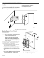
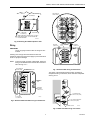
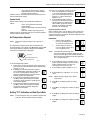
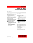
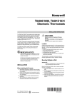
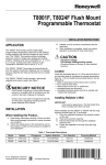
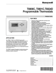
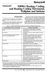
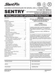
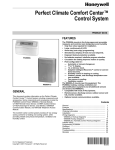
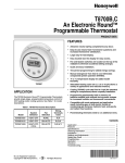
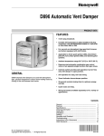
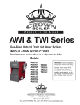
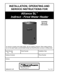
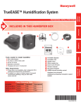
T8400C, T8401C and T8424C,D
Electronic Thermostats
PRODUCT DATA
FEATURES
T8400C and
T8401C
• Attractive styling complements any decor to the
homeowner’s delight.
• Ease-of-use means fewer homeowner questions and
increased homeowner satisfaction.
• Large display for quick easy readability.
T8424C,D
• Conveniently sized 3-1/2 x 3-1/2 thermostat with
optional decorator cover plates (3-7/8 in. x 3-7/8 in. and
5-3/4 in. x 5-3/4 in.) makes it easy to install in a variety
of locations.
• Keys are located for easy access.
• Fan and system switches are located on the lower
edge to eliminate accidental setting changes.
• Easy installation, setup and self-test saves time and
increases installer productivity.
• Manual changeover from heat to cool eliminates
unexpected system operation.
• °F or °C temperature display for added model
flexibility.
APPLICATION
The T8400C and T8401C Standard Electronic Thermostats
provide single-stage, non-programmable temperature control
for 24V heating-cooling systems with manual changeover
from heat to cool.
The T8424C Electronic Multistage Thermostat provides twostage heat and one-stage cool control.
The T8424D Electronic Multistage Thermostat provides twostage heat and two-stage cool control.
• Selectable heating cycle rate (1, 3, 4, 5, 6 or 9, 12 cph)
for a variety of applications which reduces the amount
of inventory.
• Cooling cycle rate is fixed (3 cph), the standard setting
for compressors, for speedy installation.
• Setpoints are permanently held in memory (no
batteries used) and retained during power outages for
increased installer and homeowner convenience.
• Power stealing and hard wired models available for
virtually all equipment and application needs including
gravity or radiating systems, hydronic heat,
condensing gas furnaces, gas or oil forced air and
electric heat.
Contents
Application ........................................................................ 1
Features ........................................................................... 1
Specifications ................................................................... 2
Ordering Information ........................................................ 2
Installation ........................................................................ 3
Settings and Adjustments ................................................. 8
Operation .......................................................................... 10
Checkout .......................................................................... 12
Troubleshooting ................................................................ 13
® U.S. Registered Trademark
Copyright © 2001 Honeywell • All Rights Reserved
68- 0180-3
T8400C, T8401C AND T8424C,D ELECTRONIC THERMOSTATS
SPECIFICATIONS
IMPORTANT
The specifications given in this publication do not
include normal manufacturing tolerances; therefore,
an individual unit might not exactly match the listed
specifications. Also, this product is tested and calibrated under closely controlled conditions, and some
minor differences in performance can be expected if
those conditions are changed.
T8400C, T8401C, T8424C,D TRADELINE® models include a
thermostat, wallplate for wiring and mounting thermostat and
owner’s guide.
T8400C, T8401C SUPER TRADELINE® models include a
thermostat, wallplate (for mounting and wiring thermostat),
two decorator cover plates for covering wall marks (3-7/8 in. x
3-7/8 in. and 5-3/4 in x 5-3/4 in.), and owner’s guide.
Power:
T8400C: 24 Vac nominal, 18 to 30 Vac, 50/60 Hz.
T8401C: 24 Vac nominal, 18 to 30 Vac, 50/60 Hz.
T8424C,D: 24 Vac nominal, 18 to 30 Vac, 50/60 Hz.
Ambient Temperature Range: 40°F (4°C) to 110°F (43°C).
Shipping Temperature Range: -20°F (-29°C) to 120°F
(49°C).
Operating Relative Humidity: 5% to 90% RH, noncondensing.
Cycle Rates (at 50% Load):
Heating: Selectable at 1, 3, 4, 5, 6, 9 or 12 cph. See Table
1 for cycle rate options and corresponding system
equipment.
Cooling: Fixed at 3 cph.
Table 1. Heating Cycle Rates.
System
1
Hydronic heat, condensing
gas furnacesa
3
Special applicationsb
Electrical Ratings:
Heating: .02 to 1.5A run; 3.5A inrush.
Cooling: .02 to 1.5A run; 7.5A inrush.
Fan: .02 to 0.5A run; 2.5A inrush.
Temperature Adjustment:
Setpoint temperature is adjusted by using the ▲ or ▼
keys. One press changes the setpoint one degree; pressing and holding changes the setpoint several degrees.
4, 5
Gas or oil forced air (default)
6
Electric heat
9
Special
Current Draw:
T8400C Power Stealing Thermostat requires less than
0.25 mA current draw when the thermostat calls for heat
and is compatible with most 24V microprocessor systems.
The T8400C Power Stealing Thermostat can be used in
any non-millivolt application where the T8401C and
T8424C,D Hard Wired Thermostats cannot be used. For
further detail, see Power Stealing in the Operation section.
Cycles Per Hour
Steam, gravity
a High
bRefer
applicationsb
12
efficiency furnace.
to equipment manufacturer’s instructions.
Finish:
T8400C, T8401C and T8424C,D TRADELINE® AND SUPER
TRADELINE®: Taupe finish.
T8400C, T8401C and T8424C,D STANDARD MODELS:
Premier White® finish and only available in builder packs of
20.
Accessory: Decorator cover plates (for covering wall marks):
5-3/4 in. x 5-3/4 in. and 3-7/8 in. x 3-7/8 in.
Dimensions: See Fig. 1 or 2.
Temperature Setting Range: 40°F (4°C) to 99°F (37°C).
ORDERING INFORMATION
When purchasing replacement and modernization products from your TRADELINE® wholesaler or distributor, refer to the
TRADELINE® Catalog or price sheets for complete ordering number.
If you have additional questions, need further information, or would like to comment on our products or services, please write or
phone:
1. Your local Home and Building Control Sales Office (check white pages of your phone directory).
2. Home and Building Control Customer Relations
Honeywell, 1985 Douglas Drive North
Golden Valley, Minnesota 55422 (800) 468-1502
In Canada—Honeywell Limited/Honeywell Limitée, 35 Dynamic Drive, Scarborough, Ontario M1V 4Z9.
International Sales and Service Offices in all principal cities of the world. Manufacturing in Australia, Canada, Finland, France,
Germany, Japan, Mexico, Netherlands, Spain, Taiwan, United Kingdom, U.S.A.
68-0180-3
2
T8400C, T8401C AND T8424C,D ELECTRONIC THERMOSTATS
WALLPLATE
THERMOSTAT
AND WALLPLATE
THERMOSTAT
3-1/2 (89)
2-7/8 (78)
1-3/16
(55)
2-1/2 (64)
UP
W
1-1/2
(37)
Y
2-7/8
(78)
3-1/2
(89)
G
Set
Room
R
C
FAN
Auto On
SYSTEM
Cool Off Heat
M10283A
Fig. 1. T8400/T8401 Thermostat dimensions in in. (mm).
INSTALLATION
WALLPLATE
4-3/8 (111)
When Installing this Product…
3-5/16 (84)
1.
2.
2-3/8
(70)
3.
4.
THERMOSTAT
AND WALLPLATE
1-3/16
(55)
THERMOSTAT
5-1/2 (140)
Read these instructions carefully. Failure to follow them
could damage the product or cause a hazardous condition.
Check the ratings given in the instructions and on the
product to make sure the product is suitable for your
application.
Installer must be a trained, experienced service technician.
After installation is complete, check out product operation as provided in these instructions.
CAUTION
Disconnect power supply before beginning wiring
to prevent electrical shock or equipment damage.
Set
FAN
Auto On
3-1/2
(89)
Room
MERCURY NOTICE
If this control is replacing a control that contains
mercury in a sealed tube, do not place your old control
in the trash. Dispose of it properly.
SYSTEM
Cool Off Heat Em. Ht.
M18585
Contact your local waste management authority for
instructions regarding recycling and the proper
disposal of the control. If you have questions, call the
Honeywell Customer Response Center at
1-800-468-1502.
Fig. 2. T8424 Thermostat dimensions in in. (mm).
3
68-0180-3
T8400C, T8401C AND T8424C,D ELECTRONIC THERMOSTATS
Location
—
—
—
—
Install the thermostat about 5 ft (1.5m ) above the floor in an
area with good air circulation at average temperature. See
Fig. 3. Do not install the thermostat where it can be affected
by:
— drafts or dead spots behind doors and in corners.
hot or cold air from ducts.
radiant heat from the sun or appliances.
concealed pipes and chimneys.
unheated (uncooled) areas such as an outside wall behind
the thermostat.
YES
NO
NO
5 FEET
[1.5 METERS]
NO
M10308
Fig. 3. Typical location of thermostat.
Mounting Decorator Cover Plate and
Wallplate to Wall
5-3/4 IN. x 5-3/4 IN.
DECORATOR
COVER PLATE
WALL
IMPORTANT
Level for appearance only. The thermostat functions
normally even when not mounted level.
1
NOTE: The TRADELINE® models include a thermostat and
wallplate (for wiring and mounting thermostat).
T8400C, T8401C SUPER TRADELINE® models
include a thermostat, wallplate (for wiring and mounting thermostat) and two decorator cover plates (for
covering wall marks).
2
WALL
ANCHORS (2)
Mount decorator cover plate (SUPER TRADELINE® model
only), wallplate, T8400C, T8401C or T8424C,D, and the
screws provided (see Fig. 4 or 5) as follows:
1.
2.
3.
4.
5.
Place the desired decorator cover plate and the wallplate at the desired location on the wall.
Pull the thermostat wire through the entrance hole on
the decorator cover plate, then through the wallplate
entrance hole.
Select the two mounting holes that best fit the application.
Fasten the decorator cover plate and the wallplate to
the wall using the screws provided.
After wiring the wallplate, plug the hole to prevent drafts
from affecting the thermostat; see Wiring section.
68-0180-3
4
1
3-7/8 IN. x 3-7/8 IN. DECORATOR COVER PLATE (SELECT MODELS).
2
DRILL 3/16 INCH HOLES (IF DRYWALL) OR 7/32 (PLASTER OR WOOD)
WHEN USING WALL ANCHORS.
M11041C
Fig. 4. Mounting the T8400 and T8401 decorator
cover plate and wallplate to wall.
T8400C, T8401C AND T8424C,D ELECTRONIC THERMOSTATS
WALL
KEEP WIRING IN
SHADED AREA
WALL
ANCHORS (2)
1
G
C
W2
R
Y2
MOUNTING
SCREWS (2)
1
W1
WALLPLATE
B
Y
WHEN USING WALL ANCHORS, DRILL 3/16 INCH
HOLES FOR DRYWALL, 7/32 INCH HOLES FOR
PLASTER OR WOOD.
O
M12202A
Fig. 5. Mounting the T8424 wallplate to wall.
Wiring
MOUNTING
SCREW HOLE
WIRING ENTRANCE
HOLE
MOUNTING
SCREW HOLE
IMPORTANT
Use an 18-gauge maximum wire for wiring the thermostats.
All wiring must comply with local electrical codes and
ordinances. Disconnect the power supply to prevent electrical
shock or equipment damage.
NOTE: To ensure proper mounting of thermostat, restrict all
wiring to the shaded area on the left side of the terminals. See Fig. 6 or 7.
KEEP WIRING IN
SHADED AREA
M20211
Fig. 7. Restrict T8424 wiring to shaded area.
ALTERNATE MOUNTING
SCREW HOLE
The shape of the terminals permits insertion of straight or
wraparound wiring connections; either method is acceptable.
See Fig. 8 or 9.
W
Y
G
W
MOUNTING
SCREW
HOLE
R
C
Y
ALTERNATE
MOUNTING
SCREW HOLE
G
FOR WRAPAROUND
STRIP 7/16 IN. (11 MM)
WIRING ENTRANCE HOLE
MOUNTING
SCREW HOLE
M11023
R
FOR STRAIGHT INSERTION
STRIP 5/16 IN. (8 MM)
Fig. 6. Restrict T8400 and T8401 wiring to shaded area.
C
TERMINAL SCREW
M11232
Fig. 8. T8400 and T8401 wiring connections.
5
68-0180-3
T8400C, T8401C AND T8424C,D ELECTRONIC THERMOSTATS
TERMINAL
SCREW
FOR STRAIGHT
INSERTION STRIP
5/16 IN. (8 MM)
T8400C, T8401C
FOR WRAPAROUND
STRIP 7/16 IN. (11 MM)
W
COOLING
CONTACTOR
Y
G
G
R
2
FAN
RELAY
C
C
1
L1
(HOT)
W2
1
R
L1
(HOT)
Y2
L2
T
T
OIL PRIMARY
CONTROL
24V
L2
W1
B
Y
1
POWER SUPPLY. PROVIDE DISCONNECT MEANS AND
OVERLOAD PROTECTION AS REQUIRED.
2
IN T8401C INSTALLATIONS, CONNECT C TERMINAL.
O
M11022B
Fig. 11. T8400C/T8401C heat-cool wiring diagram
in oil heating/electric cooling system. Oil
primary has its own transformer.
M20212
Fig. 9. T8424 wiring connections.
The T8400C Thermostats steal power through the heating
and cooling system controls and are adaptable to most 4-wire,
18 to 30 Vac heating-cooling systems.
T8424
STAGE-ONE
HEATING
W1
W2
The T8401C and T8424C,D Thermostats are powered directly
from the system transformer and are adaptable to most
5-wire, 18 to 30 Vac heating-cooling systems. Refer to Fig. 10
through 14 for typical wiring hookups.
1ST STAGE
COOLING
Y
Y2
2ND STAGE
COOLING
G
R
C
T8400C, T8401C
W
COOLING
CONTACTOR
Y
L1
(HOT)
G
C
1
HEATING
PRIMARY
CONTROL
1
L1
(HOT)
FAN
RELAY
24V
L2
1
POWER SUPPLY. PROVIDE DISCONNECT MEANS AND
OVERLOAD PROTECTION AS REQUIRED.
2
IN T8401C INSTALLATIONS, CONNECT C TERMINAL.
POWER SUPPLY. PROVIDE DISCONNECT MEANS AND
OVERLOAD PROTECTION AS REQUIRED.
M20213
Fig. 12. T8424C,D two-stage heat and two-stage cool
system with manual changeover wiring diagram.
24V
M11021B
Fig. 10. T8400C/T8401C heat-cool wiring diagram
in single transformer system with
gas heat/electric cooling.
68-0180-3
FAN
RELAY
L2
R
2
STAGE-TWO
HEATING
1
6
T8400C, T8401C AND T8424C,D ELECTRONIC THERMOSTATS
ZONE 1
T8400C, T8401C
C
4
2
ZONE 2
T8400C, T8401C
R
W
4
R8239A1052
C
Y
W
C
W
ZONE 3
T8400C, T8401C
R
R8222B1067
R
C
4
ZONE 4
T8400C, T8401C
R
W
4
C
W
R
R8222B1067
R8222B1067
G
L2
1
3
L1
(HOT)
3
ZONE 2
VALVE OR
DAMPER
MOTOR
3
1
ZONE 1
VALVE OR
DAMPER
MOTOR
3
ZONE 3
VALVE OR
DAMPER
MOTOR
ZONE 4
VALVE OR
DAMPER
MOTOR
POWER SUPPLY. PROVIDE DISCONNECT MEANS
AND OVERLOAD PROTECTION AS REQUIRED.
3 USE FOR 3-WIRE ZONE VALVE OR DAMPER.
4 IN T8401C INSTALLATIONS, CONNECT C TERMINAL.
2 USE ONE R8239 FOR EVERY FOUR ZONES.
M10285A
Fig. 13. T8400C/T8401C heat only wiring diagram for controlling incompatible or 3-wire zone valves or dampers. Heating
equipment is operated by end switch on the zone valve or motor, or by thermostat in master zone.
T8400C, T8401C
W
Y
G
R
6
D892/M892
4
197516A
CABLE
C
L8148E1265
4
4
3
2
TV
T
W
Z
1K
HIGH LIMIT
CONTROLLER
2
3 FUSE
R
1K2
3
B
2
5
1
1
POLARIZED 4-PRONG
MALE MOLEX PLUG AND
4-PRONG FEMALE
MATING PLUG ON CABLE
1
6-PRONG FEMALE MOLEX
B1
RECEPTABLE IN L8148E
AND 5-PRONG MALE
5
MOLEX PLUG ON CABLE
B2
REMOVE PLUG-IN THAT JUMPERS PINS 2 AND 3 WHEN USING VENT
DAMPER.
3
AFTER VENT DAMPER IS PLUGGED INTO L8148E1265, FUSE BLOWS
WHEN THERMOSTAT FIRST CLOSES. AFTER FUSE BLOWS, L8148E1265
OPERATES ONLY WHEN VENT DAMPER IS CONNECTED.
4
SEE VENT DAMPER PRODUCT SPECIFICATIONS FOR INTERNAL
SCHEMATICS.
5
B1 IS 1/4 IN. TAB TERMINAL.
6
IN T8401C INSTALLATIONS, CONNECT C TERMINAL.
C2
L1
L2
CIRCULATOR
1
L1
(HOT)
POWER SUPPLY. PROVIDE DISCONNECT MEANS AND OVERLOAD
PROTECTION AS REQUIRED.
2
C1
1K1
L2
S8610
24V GND
24V
M10286
Fig. 14. T8400C/T8401C heat only wiring diagram with L8148E1265 (with internal plug) wired
directly to vent damper in hydronic intermittent pilot system.
7
68-0180-3
T8400C, T8401C AND T8424C,D ELECTRONIC THERMOSTATS
Mounting Thermostat to Wallplate
1.
2.
Engage the tabs at the top of the thermostat and wallplate.
Swing down the thermostat and press the lower edge of
the thermostat onto the wallplate to latch. See Fig. 10.
SETTINGS AND ADJUSTMENTS
Setting Fan and System Switches
Fan and system settings are controlled manually using the
switches located at the bottom of the thermostat case. See
Fig. 17 or 18.
DASHED LINES INDICATE TABS
ON BACK OF THERMOSTAT
TEMPERATURE DISPLAY
Set
Set
Room
Room
INCREASE
SETTING
FAN
Auto
FAN
Auto On
SYSTEM
Cool Off Heat
SYSTEM
Cool Off Heat
Set
A ENGAGE TABS AT TOP
Room
DECREASE
SETTING
OF THERMOSTAT WITH
SLOTS ON WALLPLATE.
B
M11025B
PRESS LOWER EDGE OF
CASE TO LATCH.
Fig. 15. Mounting T8400 or T8401 thermostat to wallplate.
FAN
Auto On
SYSTEM
Cool Off Heat
DASHED LINES INDICATE TABS
ON BACK OF THERMOSTAT
FAN SWITCH
SYSTEM SWITCH
M11020A
Fig. 17. T8400 and T8401 temperature
display and system switches.
TEMPERATURE DISPLAY
INCREASE SETTING
DECREASE SETTING
AuFtoAN
On
S
CoSoY
l OTffEM
Heat
A ENGAGE TABS AT TOP OF THERMOSTAT
WITH SLOTS ON MOUNTING PLATE.
AN
AuFto
On
FAN SWITCH
S S
CooY
l OTffEM
Heat
M14678
SYSTEM SWITCH
Fig. 18. T8424 temperature display and system switches.
FAN
Auto
On
Fan Switch
Fan switch settings are:
ON: The fan runs continuously. Use for
improved air circulation.
AUTO: Normal setting for most homes. In
cooling, the fan starts and stops with the
cooling equipment. In heating, the fan is
controlled directly by the heating
equipment and may start a few minutes
after the heating equipment turns on (on
CooSYSTE
l Off M
Hea
t
B PRESS LOWER EDGE OF
CASE TO LATCH.
M14677
Fig. 16. Mounting T8424 thermostat to wallplate.
68-0180-3
8
T8400C, T8401C AND T8424C,D ELECTRONIC THERMOSTATS
most systems). When using an electric
heat thermostat, the fan starts and stops
with the heating equipment.
Slide the switch in the bottom left corner of the thermostat to
select the desired fan setting.
System Switch
System switch settings control thermostat operation as
follows:
COOL: The thermostat controls the
cooling system.
HEAT: The thermostat controls the heating
system.
OFF: Both heating and cooling are off.
Slide the switch in the bottom right corner of the thermostat to
select the desired system setting.
Set Temperature Setpoint
The temperature setpoint and the room temperature are
shown separately on the display. The ▼ indicator points to Set
when the temperature setpoint is displayed and to Room
when the room temperature is displayed.
INDICATOR
Room
M14683
M14686
Optional System Checkout
When in steps B and C only, the ▼ key can be used to turn
heat or cool outputs on and off. Change the system switch
setting to test heat or cool outputs. No action takes place If the
system is in the Off position.
EXAMPLES:
—
System setting at HEAT: If
heat is on, the ▼ key turns it
off; if heat is off, ▼ turns it on.
NOTE: Temperature setpoint range is 40° to 99°F (4° to
37°C).
Set
To set the °F/°C indication and heat cycle rate:
1. If the room temperature is displayed
in °F, set the temperature setpoint to
52°F. If the room temperature is displayed in °C, set the temperature
setpoint to 11°C.
2. Press the ▲ and ▼ keys simultaneously for more than one second to
light all segments on display and to
enter installer setup mode. When
the keys are released, a two-digit
software code is displayed.
ROOM TEMPERATURE
SETPOINT TEMPERATURE
—
To set the temperature setpoint:
1. Select Heat or Cool by sliding the system switch in the
lower right corner of the thermostat to the desired mode.
See Fig. 17 or 18.
2. To display the selected temperature setpoint
on the digital display, press either the ▲ or ▼
key once. The temperature setpoint is disM14680
played for approximately five seconds as the
indicator points to Set and flashes.
3. To increase the temperature setpoint press
the ▲ key. Each press changes the setpoint
one degree; press and hold to change the setM14681
point several degrees.
4. To decrease the setpoint temperature press
the ▼ key. Each press changes the setpoint
one degree; press and hold to change the
M14682
setpoint several degrees.
Setting °F/°C Indication and Heat Cycle Rate
M14684
M14685
NOTE: In installer setup mode only, each
press of the ▲ key momentarily displays 01 and
each press of the ▼ key momentarily displays 02.
When the keys are released, these two-digit codes
are no longer displayed.
3.
M11247
System setting at COOL: If
cool is on, ▼ key turns it off; if
cool is off, ▼ turns it on.
4.
5.
Press the ▲ key. Factory information is displayed. A typical example is shown, but information displayed varies by model. This
information is for factory use only.
Press the ▲ key again to display °C or °F.
Press the ▼ key to change the °C or °F indication.
NOTE: Steps 6 through 9 apply only to T8424
Thermostats.
6.
Press ▲ key to display number of cooling
stages.
7.
Press ▼ key to change the number of cooling
stages.
8.
Press ▲ key to display the number of heating
stages.
9.
Press ▼ key to change the number of heating
stages.
M14687
M14688
M14689
M20208
NOTE: To save changes to the °F/°C indication and the heat
cycle rate, all seven steps must be completed.
M20207
M20209
M20210
9
68-0180-3
T8400C, T8401C AND T8424C,D ELECTRONIC THERMOSTATS
10.
Press the ▲ key to display the heat cycle
rate of 1, 3, 4, 5, 6, 9 or 12. When set at two
stages of heat (T8024 only) , both stages
operate at selected cycle rate. If the desired
M20230
cycle is displayed, press the ▲ key to exit
the installer setup mode. To change the heat cycle rate,
press the ▼ key to scroll between cycle rates. Stop
scrolling when the desired rate is displayed. See Table 2
for the cycle rate options and the corresponding system
equipment.
Table 2. Heating Cycle Rates.
System
1
Hydronic heat, condensing
gas furnacesa
3
Special applicationsb
Gas or oil forced air (default)
Electric heat
Special
a High
applicationsb
The thermostats control temperature closer to setpoint than
electromechanical thermostats. This is because proportional
plus integral control maintains the same indoor temperature
independent of the outdoor temperature. Thus the T8400C
and T8401C Thermostats provide tight temperature control
with virtually no noticeable swings in temperature setpoint, a
condition referred to as droop. This zero droop performance
provides improved occupancy comfort. Occupants do not
need to continually adjust thermostat settings to be
comfortable, even during severe weather. Electromechanical
thermostats have little control over droop, thus resulting in
room temperature changes of 3°F to 5°F as outdoor
temperature varies.
4, 5
6
9
12
efficiency furnace.
to equipment manufacturer’s instructions.
b Refer
11.
12.
13.
14.
The T8400C and T8401C Standard Electronic Thermostats
provide single-stage temperature control using proportional
plus integral (P+I) control to eliminate droop. The T8424C
provides two-stage heat and two-stage cool temperature
control with P+I control. The T8424D Electronic Multistage
Thermostat provides two-stage heat and two-stage cool
temperature control and also uses P+I control.
Zero Droop Performance
Cycles Per Hour
Steam, gravity
OPERATION
Press the ▲ key to display algorithm configuration.
Press the ▲ key again to change the
M18419
algorithm to C1 or C3.
C1 = standard algorithm.
C3 = aggressive algorithm (can cause
overshooting).
Press the ▲ key again. Current algorithm
(CC) is displayed. A typical example is
shown, but CC varies by model. This informaM18420
tion is for factory use only.
Press the ▲ key to save all changes, exit
installer setup mode and return to normal operation.
NOTE: After exiting installer setup mode, change the setpoint to the desired room temperature.
Power Stealing
Unlike hard wired thermostats which are powered directly
from the system transformer, the T8400C Thermostat steals
power through the heating and cooling system controls and
can be used in applications where existing wiring does not
permit using hard wired thermostats. See Fig. 19 and 20.
Previous Honeywell power stealing thermostats required 80
mA of load current when the heating and cooling was on. The
T8400C Thermostat requires only 2.5 mA of load current (1/32
of previous models) when the heating or cooling is on. When
the heating or cooling is off, the thermostat operates at 0.1 mA
(1/100 of previous models). Other Honeywell power stealing
thermostats are available, but they have different powering
requirements than the T8400C. This low current draw makes
the T8400C applicable to most 24V heating and cooling
systems.
The T8400C, T8401C and T8424C,D Thermostats only
operate when mounted on the wallplate with 24V applied.
Batteries are not required for operation because temperature
setpoints and configuration settings are retained permanently
in memory.
68-0180-3
10
T8400C, T8401C AND T8424C,D ELECTRONIC THERMOSTATS
L1
(HOT) L2
1
R
FAN SWITCH
FAN RELAY
ON
G
THERMISTOR
SENSOR
AUTO
THERMOSTAT
LOGIC
HEAT RELAY
SYSTEM SWITCH
W
HEAT
OFF
COOL RELAY
COOL
Y
POWER
SUPPLY
LOGIC AND
CONTROL
MOSFET
1
POWER SUPPLY. PROVIDE DISCONNECT MEANS AND
OVERLOAD PROTECTION AS REQUIRED.
MOSFET
M10360
Fig. 19. T8400C power 0stealing internal schematic.
R
FAN SWITCH
FAN RELAY
ON
G
AUTO
1
RELAY
THERMISTOR
SENSOR
L1
(HOT)
L2
THERMOSTAT
LOGIC
HEAT RELAY
SYSTEM SWITCH
W
HEAT
OFF
COOL RELAY
COOL
Y
POWER
SUPPLY
C
1
POWER SUPPLY. PROVIDE DISCONNECT MEANS AND OVERLOAD PROTECTION AS REQUIRED.
M10292
Fig. 20. T8401C hardwired internal schematic.
Energy Savings
You can save energy with the T8400C, T8401C and
T8424C,D Thermostats in the heating mode by lowering the
temperature setting 5°F (3°C) to 10°F (5°C) at night and
during the day. You can also save energy in the cooling mode
by raising the temperature setting during the day before you
leave for work or school. Savings can be as high as 7% to
33% depending on your home, where you live, the number of
11
energy saving periods you choose and your energy savings
temperature settings. Refer to the maps in the Operation
section for typical energy savings.
Sequence of Operations
The Fan, Heat and Cool outputs are relay or mosfet
controlled. A loss of ac power or a change in the SYSTEM
switch setting can cause the outputs to turn off. The truth table
shows the sequence of operations for the FAN settings and
SYSTEM modes. See Table 3 Sequence of Operations.
68-0180-3
T8400C, T8401C AND T8424C,D ELECTRONIC THERMOSTATS
Table 3. Sequence of Operations.
FAN Switch Settings
SYSTEM Switch Settings
Call for Action
Energize Terminals
Display Icons
Auto
Off
None
None
None
None
a In
On
Any
Any
G
Auto
Cool
Cooling
G,Y
Auto
Heat
Heating
Wa,b
electric heat models, W and G are energized with calls for heat.
and W2 terminals are energized in the T8424C,D models.
b W1
Fan Control
3.
The FAN switch settings are On and Auto.
ON:The fan runs continuously.
AUTO:In cooling, the fan starts and stops
with the cooling equipment. In heating, the
fan starts a few minutes after the heating
equipment turns on. When using an
electric heat thermostat, the fan starts and
stops with the heating equipment.
Cooling
CAUTION
Low Temperature Hazard.
Operating at too low of an outdoor temperature
can cause compressor damage.
Do not operate cooling if outdoor temperature is below
50°F (10°C). Refer to manufacturer recommendations.
Heat Mode
With the SYSTEM switch at Heat, the thermostat controls the
heating system. On a call for heat, the W terminal is energized
and a flame is shown on the digital display.
Cool Mode
With the SYSTEM switch at Cool, the thermostat controls the
cooling system. On a call for cool, the G and Y terminals are
energized and a snowflake is shown on the digital display.
Minimum Off-Timer
A minimum off-timer in the T8400C, T8401C and T8424C,D
assures that the cooling compressor does not come on again
for at least five minutes after it turns off. The minimum-off
timer is triggered when the compressor turns off and when the
system switch is changed. If the compressor turns off when
the setpoint is changed, then the minimum-off timer is
triggered. Power interruption and power restoration also
trigger the minimum off-timer. The minimum-off timer operates
only during the cooling cycle on the thermostat.
CHECKOUT
Heating
1.
2.
Slide the system switch to Heat and the fan switch to
Auto.
Press and hold the ▲ key to raise the temperature setting several degrees above the room temperature. After
approximately ten seconds the W terminal is energized
and the heating equipment starts.
68-0180-3
12
Press the ▼ key to lower the temperature setting below
the room temperature. Heating equipment should stop.
To avoid compressor damage, allow the compressor to
remain off for five minutes before restarting.
1. Slide the system switch to Cool and the fan switch to
Auto.
2. Press the ▼ key to lower the temperature setting several degrees below the room temperature. After approximately five minutes the G and Y terminals are
energized and the cooling equipment starts.
3. Press the ▲ key to raise the temperature setting above
the room temperature. Cooling system should shut
down.
Fan
1.
2.
Slide the SYSTEM switch to Off and the FAN switch to
On. The fan should run continuously.
Slide the FAN switch to Auto. In heating, the fan is controlled directly by the heating equipment and may start a
few minutes after the heating equipment turns on (on
most systems). When using an electric heat thermostat,
the fan starts and stops with the heating equipment. In
cooling, the fan starts and stops with the cooling equipment.
Make certain all equipment responds properly to the
thermostat.
T8400C, T8401C AND T8424C,D ELECTRONIC THERMOSTATS
TROUBLESHOOTING
Refer to Fig. 21 for the proper troubleshooting procedure.
SYMPTOM
HEATING OR COOLING EQUIPMENT
WON'T OPERATE.
POSSIBLE CAUSE
ACTION
NO AC POWER TO THERMOSTAT.
• CHECK THAT C TERMINAL IS CONNECTED TO
THE SYSTEM TRANSFORMER.
• CHECK POWER TO HEATING AND COOLING EQUIPMENT
– ON-OFF SWITCH
– FUSE OR CIRCUIT BREAKER
– LOOSE 24V CONNECTION
– AT THERMOSTAT
– AT FURNACE/AIR CONDITIONER
– INCORRECT WIRING (SEE WIRING DIAGRAM)
THERMOSTAT INOPERATIVE.
CONDUCT SELF-TEST; SEE CHECKOUT SECTION.
PRESENT SETTING TOO LOW/HIGH.
ADJUST TEMPERATURE BY PRESSING
SYSTEM SWITCH ON THERMOSTAT
IN WRONG POSITION.
RESET THERMOSTAT SYSTEM SWITCH.
MINIMUM-OFF TIMES IN THERMOSTAT
IN OPERATION ON COOLING OR
FIRST STAGE HEATING.
WAIT FIVE MINUTES OR FOLLOW STEPS IN
CHECKOUT SECTION.
INCORRECT WIRING.
CHECK WIRING DIAGRAM.
HEATING OR COOLING EQUIPMENT
INOPERATIVE.
CONSULT EQUIPMENT MANUFACTURER INSTRUCTIONS.
INOPERATIVE THERMOSTAT.
REPLACE THERMOSTAT.
STILL IN INSTALLER SETUP MODE.
SEE THE SETTINGS AND ADJUSTMENTS SECTION FOR
INSTRUCTIONS ON INSTALLER SETUP MODE.
NO POWER TO THERMOSTAT.
• CHECK THAT C TERMINAL IS CONNECTED TO
THE SYSTEM TRANSFORMER.
• CHECK POWER TO HEATING AND COOLING EQUIPMENT
– ON-OFF SWITCH
– FUSE OR CIRCUIT BREAKER
– LOOSE 24V CONNECTION
– AT THERMOSTAT
– AT FURNACE/AIR CONDITIONER
– INCORRECT WIRING (SEE WIRING DIAGRAM)
THERMOSTAT MOUNTED
INCORRECTLY ON WALLPLATE.
SEE INSTALLATION INSTRUCTIONS FOR
CORRECT MOUNTING.
TEMPERATURE DISPLAY IS
INCORRECT.
THERMOSTAT IS CONFIGURED FOR
F OR C DISPLAY.
RECONFIGURE THE DISPLAY. SEE SETTINGS
AND ADJUSTMENTS SECTION.
TEMPERATURE SETTINGS WILL NOT
CHANGE. (EX: CANNOT SET THE
HEATING HIGHER OR THE
COOLING LOWER).
THE UPPER OR LOWER
TEMPERATURE LIMITS WERE
REACHED.
CHECK THE TEMPERATURE SETPOINTS; TEMPERATURE
SETTING RANGE IS 40 F (4 C) TO 99 F (37 C).
FAN DOES NOT OPERATE PROPERLY
IN HEAT OR COOL MODES.
INCORRECT WIRING.
CHECK WIRING DIAGRAM.
HEATING OR COOLING EQUIPMENT
INOPERATIVE.
CONSULT EQUIPMENT MANUFACTURER INSTRUCTIONS.
PARTIAL DISPLAY
NO DISPLAY
OR
KEYS.
M10291B
Fig. 21. Troubleshooting procedure.
13
68-0180-3
68-0180-3
14
15
68-0180-3
+RPHDQG%XLOGLQJ&RQWURO +RPHDQG%XLOGLQJ&RQWURO
+RQH\ZHOO
'RXJODV'ULYH1RUWK
*ROGHQ9DOOH\01
+RQH\ZHOO/LPLWHG+RQH\ZHOO/LPLWpH
'\QDPLF'ULYH
6FDUERURXJK2QWDULR
09=
68-0180-3 G.H. Rev. 10-01
Printed in U.S.A. on recycled
paper containing at least 10%
post-consumer paper fibers.
www.honeywell.com/yourhome