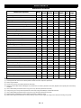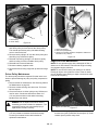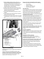
1
Contractor
Owner/Operator Manual
Models
996126 – Contractor 2WD
996148 – Contractor 4WD
Gasoline containing up to 10% ethanol (E10) or up to 10% MTBE (methyl tertiary butyl ether) is acceptable for use in this machine.
The use of any gasoline exceeding 10% ethanol (E10) or 10% MTBE will void the product warranty.
04380300 8/11
Printed in USA
ENGLISH
TABLE OF CONTENTS
Safety . . . . . . . . . . . . . . . . . . . . . . . . . . . . . . . . . . . . . . .3
Storage . . . . . . . . . . . . . . . . . . . . . . . . . . . . . . . . . . . . 30
Controls and Features . . . . . . . . . . . . . . . . . . . . . . . 10
Troubleshooting . . . . . . . . . . . . . . . . . . . . . . . . . . . . . 31
Operation . . . . . . . . . . . . . . . . . . . . . . . . . . . . . . . . . . .11
Specifications . . . . . . . . . . . . . . . . . . . . . . . . . . . . . . .35
Maintenance . . . . . . . . . . . . . . . . . . . . . . . . . . . . . . . .19
Warranty . . . . . . . . . . . . . . . . . . . . . . . . . . . . . . . . . . . 36
Maintenance Schedule . . . . . . . . . . . . . . . . . . . . . . . .19
INTRODUCTION
THE MANUAL
PRODUCT REGISTRATION
Before operation of unit, carefully and completely read your
manuals. The contents will provide you with an
understanding of safety instructions and controls during
normal operation and maintenance.
The Ariens dealer must register the product at the time of
purchase. Registering the product will help the company
process warranty claims or contact you with the latest
service information. All claims meeting requirements during
the limited warranty period will be honored, whether or not
the product registration card is returned. Keep a proof of
purchase if you do not register your unit.
All reference to left, right, front, or rear are given from
operator standing in operation position and facing the
direction of forward travel.
ENGINE MANUAL
The engine on this unit is covered by a separate manual
specific to the engine. This manual is included in the
literature package that shipped with the unit. Refer to this
manual for engine service recommendations. If the engine
manual is not available, contact the engine manufacturer for
a replacement manual.
MODEL AND SERIAL NUMBERS
When ordering replacement parts or making service
inquiries, know the Model and Serial numbers of your unit
and engine.
Numbers are located on the product registration form in the
unit literature package. They are printed on a serial number
label, located on the frame of your unit.
Customer Note: If the Dealer does not register your
product, please fill out, sign and return the product
registration card to Ariens or go to www.ariens.com on the
internet.
UNAUTHORIZED REPLACEMENT PARTS
Use only Ariens replacement parts. The replacement of any
part on this vehicle with anything other than a Ariens
authorized replacement part may adversely affect the
performance, durability, or safety of this unit and may void
the warranty. Ariens disclaims liability for any claims or
damages, whether warranty, property damage, personal
injury or death arising out of the use of unauthorized
replacement parts. To locate your nearest Ariens Dealer, go
to www.ariens.com on the internet.
DISCLAIMER
Ariens reserves the right to discontinue, make changes to,
and add improvements upon its products at any time without
public notice or obligation.The descriptions and
specifications contained in this manual were in effect at
printing. Equipment described within this manual may be
optional. Some illustrations may not be applicable to your
unit.
DEALER DELIVERY
Dealer should:
1. Check all controls for proper function.
2. Fill out Original Purchaser Registration Card and
return the card to Ariens.
Serial Number Label
Figure 1
3. Explain Limited Warranty Policy.
Vehicle Information
Model No.
_________________
Serial No.
_________________
Engine Model No.
_________________
Engine Serial No.
_________________
4. Explain recommended lubrication and maintenance.
Advise customer on adjustments.
5. Instruct customer on controls and operation of unit.
Discuss and emphasize the Safety Precautions. Give
customer Owner/Operator, Parts, and Engine
Manuals. Advise customer to thoroughly read and
understand them.
GB - 2
© Copyright 2011 Ariens Company
EMISSION CONTROL SYSTEM
This equipment and/or its engine may include exhaust and
evaporative emissions control system components required
to meet U.S. Environmental Protection Agency (EPA) and/or
California Air Resources Board (CARB) regulations.
Tampering with emission controls and components by
unauthorized personnel may result in severe fines or
penalties. Emission controls and components can only be
adjusted by an Ariens Company dealer or an authorized
engine manufacturer's service center. Contact your Ariens
Company Equipment Retailer concerning emission controls
and component questions.
SAFETY
SAFETY ALERTS
REQUIRED OPERATOR TRAINING
Look for these symbols to point out important
safety precautions. They mean:
Personal Safety Is Involved!
Original purchaser of this unit was instructed by the seller on
safe and proper operation. If unit is to be used by someone
other than original purchaser; loaned, rented or sold,
ALWAYS provide this manual and any needed safety
training before operation.
Become Alert!
SAFETY DECALS AND LOCATIONS
Obey The Message!
ALWAYS replace missing or damaged safety decals. Refer
to Figure 2 for safety decal locations.
Attention!
The safety alert symbols above and signal words below are
used on decals and in this manual.
Read and understand all safety messages.
1. Keep all safety decals clean and legible.
2. Replace all damaged or missing decals. Order new
safety decals through your Ariens dealer.
DANGER: IMMINENTLY HAZARDOUS
SITUATION! If not avoided, WILL RESULT
in death or serious injury.
WARNING: POTENTIALLY HAZARDOUS
SITUATION! If not avoided, COULD
RESULT in death or serious injury.
CAUTION: POTENTIALLY HAZARDOUS
SITUATION! If not avoided, MAY RESULT in
minor or moderate injury. It may also be
used to alert against unsafe practices.
NOTATIONS
NOTE: General reference information for proper operation
and maintenance practices.
IMPORTANT: Specific procedures or information required to
prevent damage to unit or attachment.
PRACTICES AND LAWS
Practice usual and customary safe working precautions, for
the benefit of yourself and others. Understand and follow all
safety messages. Be alert to unsafe conditions and the
possibility of minor, moderate, or serious injury or death.
Learn applicable rules and laws in your area, including those
that may restrict the age of the operator.
GB - 3
2
1
3
5
4
6
7
8
10
9
11
12
Figure 2
13
1. DANGER! GUARD MISSING
2. WARNING! ROLLOVER - FALLING OFF HAZARD
• Always wear seat belts
Do not operate vehicle without guards in
place.
• Drive very slowly when turning.
• Always use brakes when going down a
slope.
• Reduce speed on rough or hilly ground.
• Never attempt wheelies, jumps or other
stunts.
GB - 4
3. DANGER! BATTERY
•
8. WARNING!
To prevent serious injury or death:
Avoid battery acid spills. Do not get
battery acid on eyes, face or other body
parts.
• Read and understand Operator’s Manual
before using and review annually.
•
Do not add water or other liquids to
battery.
• Do not operate without proper training or
instructions.
•
Battery fumes are explosive
• Operate only with guards installed and in good
condition.
• Keep away from moving parts.
• NEVER operate with passenger - except in
seat or seats provided (one person per seat
position). Passengers affect balance and
steering and increase risk of losing control.
• Support vehicle securely before working
beneath.
4. DANGER! TRAILER TOWING INFORMATION
• keep arms, legs, loose clothing and other
appendages inside vehicle at all times.
• Tow load at speed slow enough to maintain
control.
• do not operate vehicle in a dangerous manner.
When ascending or descending hills - travel
slowly, travel straight up and down, and avoid
turning if possible.
• Do not exceed towing capacity or tongue
weight.
5. WARNING! HOT SURFACES!
• Use caution and slow down when approaching
wet, loose, slippery surfaces or unfamiliar
terrain.
• DO NOT touch parts which are hot from
operation. ALWAYS allow parts to cool.
• Avoid sudden stops, starts turns or direction so
as not to shift your load, endanger your
passengers or lose control of the vehicle.
6. CAUTION!
• Under all day or night travel conditions:
operate this vehicle at speeds that will permit it
to be brought to a stop in a safe manner.
• DO NOT exceed rated current of 12V 20A.
• Prior to each use: inspect tires, engine oil
level, brakes, steering mechanism and overall
vehicle condition. If any problem exists, DO
NOT OPERATE vehicle until safe operation
can be restored.
7. CAUTION!
Before leaving vehicle:
• Stop engine
• Set parking brake
• DO NOT EXCEED PAYLOAD
recommendations and avoid loads which can
not be centered and secured.
• Remove key
• This vehicle is built for off-road use only as
speeds NOT TO EXCEED 25 mph. Any
attempt to make unauthorized modifications of
the original manufacturer’s design will make
the modifying party immediately and totally
responsible, henceforth, for meeting
compliance with all applicable Federal, State
and Local laws, guidelines and regulations.
9. WARNING!
Before filling tank with gasoline:
GB - 5
•
let engine cool.
•
Gas vapors can ignite and explosion can
occur.
Practice Safe Maintenance
10. WARNING! 2WD DO NOT OVERLOAD!
•
Understand procedure before doing work. Use proper tools
and equipment. Refer to this manual for additional
information.
Overloading can cause loss of control.
Work in a clean, dry area.
11. WARNING! 4WD DO NOT OVERLOAD!
•
Place the vehicle in neutral, set parking brake, turn off
engine and remove key before performing maintenance.
Chock wheels if you must perform maintenance on a slope.
Overloading can cause loss of control.
Make sure all moving parts have stopped and all system
pressure is relieved.
12. WARNING! CAB ROLLOEVER PROTECTION
Allow the engine to cool completely.
•
Vehicle rollover could cause severe injury or
death. This cab frame is not designed or
intended to provide rollover protection.
•
Always wear seat belts.
Disconnect battery ground cable (-) before servicing or
adjusting electrical systems or before welding.
Inspect all parts. Make sure parts are in good condition and
installed properly.
Remove build-up of grease, oil or debris.
13. WARNING! IMPROPER USE CAN RESULT IN SEVERE
INJURY OR DEATH!
Remove all tools and unused parts from the unit before
operation.
•
Use an approved motorcycle helmet and
protective gear when warranted.
•
Never use on public roads, streets or
highways.
Be prepared if a fire starts.
•
Never carry passengers, except in seat
provided.
Keep emergency numbers for doctor, ambulance, hospital
and fire department near phone.
•
Never use drugs or alcohol.
•
No driver under age of 16.
Prepare for Emergencies
Keep a first aid kit and fire extinguisher handy.
Wear Protective Equipment
Wear protective clothing and equipment.
Wear clothing and equipment appropriate for the job. Avoid
loose-fitting clothing.
Because prolonged exposure to loud noise can cause
hearing impairment or hearing loss, it is best to wear suitable
hearing protection such as earmuffs or earplugs.
General Safety
Because operating equipment safely requires your full
attention, avoid wearing radio headphones while operating
machinery.
For Your Protection
Thoroughly read and understand the instructions given in
this manual before operation. Refer to the “Safety Label”
section, read all instructions noted on the decals.
Wear seat belts at all times when operating vehicle.
Do not allow anyone to operate this equipment who has not
fully read and comprehended this manual and who has not
been properly trained in the safe operation of the equipment.
Tire Safety
Tire changing can be dangerous and should be performed
by trained personnel using correct tools and equipment.
Before Operating
•
When inflating tires, use a clip-on chuck and
extension hose long enough for you to stand to
one side–not in front of or over tire assembly. Use
a safety cage if available.
•
When removing and installing wheels, use
wheel-handling equipment adequate for weight
involved.
This unit is not to be driven on public roads. Operating this
unit on public roads could be against the law and may be
hazardous. Injury or death may result.
Do not operate this vehicle under the influence of alcohol or
drugs.
Always inspect the vehicle before operating it. See
"Pre-Start Check List" on page 11.
Safe Operating Procedures
Do not operate this machine unless all safety shields are in
place and all badly worn, broken or missing parts have been
properly replaced.
Wear appropriate protective gear and clothing such as
safety helmet, goggles, gloves, coveralls, etc., when
conditions warrant.
The safe operation of any machinery is an important
concern to all consumers. Your vehicle has been designed
with many built-in safety features. However, no one should
operate this vehicle before carefully reading this Operator’s
Manual. Also read all instructions noted on the safety
decals.
No driver under age of 16.
GB - 6
Personal Safety
Be familiar with all functions of this vehicle.
Do not allow anyone to operate this vehicle who has not fully
read and comprehended this manual and who has not been
properly trained in the safe operation of this vehicle.
Do not operate vehicle while drinking or under the influence
of alcohol or drugs.
Do not allow anyone under 16 years of age to operate this
vehicle even under adult supervision. All passengers must
be at least 80 pounds and exceed a height of 4’ 9" (57
inches). Any passenger must be able to comfortably reach
the floor with their feet and grab handles with their hands.
Do not run engine indoors except when starting engine and
transporting attachment in or out of a building. Carbon
monoxide gas is colorless, odorless and deadly.
Operate with both hands on the steering wheel.
Keep all bystanders away from this vehicle during operation.
Keep children out of the operating area and under the
watchful eye of another responsible adult.
Riders may, without knowing it, place their foot on the
accelerator pedal while bracing themselves against a rough
ride. This makes it impossible to slow down the vehicle until
the passenger removes his foot from the pedal. Inform
passenger to keep his foot off the accelerator and always
slow down before the ride gets rough.
Avoid battery acid spills. Do not get battery acid on eyes,
face, or other body parts. Flush eyes and other body parts
immediately with water for at least 15 minutes if battery acid
has gotten on them.
This product is equipped with an internal combustion type
engine. DO NOT use unit on or near any unimproved,
forest-covered or brush covered land unless exhaust system
is equipped with a spark arrester meeting applicable local,
state or federal laws. A spark arrester, if it is used, must be
maintained in effective working order by operator.
Fuel is highly flammable and its vapors are explosive.
Handle with care. Use only an approved gasoline container
with an appropriately sized dispensing spout.
NO smoking, NO sparks, NO flames. ALWAYS allow engine
to cool before servicing.
NEVER fill fuel tank when engine is running or hot from
operation.
NEVER fill or drain fuel tank indoors.
NEVER OVERFILL fuel tank. See See Filling Fuel Tank on
page 23.
Replace fuel cap securely and clean up spilled fuel.
Properly remove fuel before tipping unit.
NEVER fill containers inside a vehicle or on a truck or trailer
bed with a plastic liner. Always place containers on the
ground away from your vehicle before filling.
No riders are allowed except in factory designed and
supplied seating and no more than one person in a bucket
seat and three people in a bench seat. Do not use cargo bed
for carrying people. Maximum vehicle occupancy including
driver is one person per seat position.
When practical, remove gas-powered equipment from the
truck or trailer and refuel it on the ground. If this is not
possible, then refuel such equipment on a trailer with a
portable container, rather than from a gasoline dispenser
nozzle.
Operate vehicle from driver’s seat only.
Keep the nozzle in contact with the rim of the fuel tank or
container opening at all times until fueling is complete. Do
not use a nozzle lock-open device.
Do not leave vehicle unattended with engine running.
Do not dismount a moving vehicle as serious injury or death
could occur.
Wear snug-fitting clothing to avoid entanglement with
moving parts.
If fuel is spilled on clothing, change clothing immediately.
Do not smoke while handling fuel.
Keep hands, feet, long hair, clothing and jewelry away from
moving parts and obvious pinch points to avoid getting
caught.
Do not fill tank with engine running or while engine is hot.
Allow engine to cool before filling. Spilling fuel over engine,
muffler, or a hot object may result in a fire or explosion.
Allow engine to cool before servicing the fuel system.
Keep hands, arms, feet and all bodily appendages safely
inside the confines of the vehicle. Always be aware of and
avoid tree limbs and brush that have a potential of hitting
and/or poking individuals riding the vehicle. Serious body
harm could result.
Clean up any gasoline spills immediately.
Some conditions may warrant extra safety gear to be worn
such as safety helmets and/or goggles.
Use extra caution when handling gasoline and other fuels.
They are flammable and vapors are explosive.
Do not touch engine, engine exhaust pipe and/or muffler
while they are hot.
Refuel in well ventilated areas.
Avoid pinch point hazards. Cargo bed and seat platform
hinge creating pinch points.
Battery fumes are explosive. A spark will ignite battery
fumes. Wear a face shield when charging or jumping a
battery. Follow all battery safety rules outlined in this
manual.
Keep fuel away from open flame or spark.
Store vehicle away from open flame or spark if there is fuel
in the tank.
Never attempt to start engine when there is a strong odor of
gasoline fumes present. Locate and correct cause.
Store gasoline in an approved container and keep it out of
children’s reach.
Gasoline is harmful or fatal if swallowed.
Long-term exposure to vapors can cause serious injury and
illness.
GB - 7
Avoid prolonged breathing of vapors.
Use extreme caution when driving through dry grass, brush
and other fire hazard materials. Never stop or park over
combustible materials. Keep grass and brush from collecting
on and around engine and muffler parts.
Keep face away from nozzle and gas tank opening.
Keep gas away from eyes and skin.
Support this vehicle securely before working beneath.
Chock wheels to prevent vehicle from rolling.
Be aware of cargo shifting when stopping or moving. Make
sure all cargo is properly secured and tied down. Injury could
result from loose cargo.
Mechanical Safety
Do not operate a vehicle with damaged or worn parts. Repair
all damages and worn parts before putting vehicle back in to
service.
Avoid sudden stops, starts and turns.
Never attempt to make any adjustments while engine is
running or hot. Keep clear of all rotating parts.
Always make sure vehicle pathway is clear of all objects
when backing up. Know location of persons around vehicle
and especially location of small children. Take extra
precautions when rear view is hindered by cargo.
Make sure engine surface, cooling fins and fan screen are
clean of all debris including dirt, trash and oil.
Do not attach an implement, trailer or other device to the
hitch that will produce negative tongue weight.
Always operate vehicle with drive belt enclosure installed.
Do not leave pulleys and belts exposed.
Reduce speed and payload on hilly, rough, wet, slick or
unstable ground.
Never modify any parts on the vehicle without authorization.
Unauthorized modifications will void warranty to all parts
directly and indirectly affected by the modification.
Reduce speed when loaded with cargo. Heavy cargo load
takes longer to stop.
Do not use cargo tail gate as a seat.
Do not use cargo bed as a working platform.
The power lift is designed to dump cargo only. Do not use it
to lift other objects.
Never attempt “wheelies”, jumps, or other stunts. Never
drive recklessly. Always operate your vehicle at a safe speed
that will allow you to maintain control.
Do not use vehicle as an anchor device.
Do not mount a receiver hitch type carrier platform to the
vehicle.
Front bumper and cargo bed are not designed as pusher
bars. Do not attempt to push other vehicles or implements or
damage may result.
Always make turns at a speed that will maintain control of
vehicle. Never make turns at full speed. Reduce speed
when turning empty and reduce speed even more when
turning loaded. The heavier the cargo load, the slower the
turn should be.
The four-post accessory bar is not a certified ROPS (Roll
Over Protection Structure). Always avoid roll-overs.
Do not load four-post accessory bar with heavy equipment.
Rollover could result from such loading.
Always park on level ground, stop engine, set parking brake
and remove ignition key before leaving vehicle. Chock tires if
condition warrants.
Always maintain proper tire inflation. See Tire Maintenance
on page 20.
Use extreme caution when cresting hills, approaching blind
corners, shrubs, trees or other obstructions that might limit
visibility. Proceed slowly until you are sure trail conditions
immediately ahead are safe. Use extra care when
approaching obstructions that might hide children.
Always disconnect negative battery terminal before making
adjustments to vehicle electrical system or welding on this
vehicle.
Be especially observant of operating area and terrain. Watch
for holes, rocks, or other hidden hazards. Do not operate
vehicle near the edge of drop-offs or banks.
Always check wheel lug nut torque values two hours after
initial operation and two hours after each tire repair or
replacement. Routinely check lug nut torque every 100
hours of operation. See Torque on page 20.
Keep front wheels straight when cresting hills or going over
bumps.
Do not shift transaxle unless this vehicle is fully stopped and
engine is at idle or damage may occur.
Keep safety decals clean of dirt and grime.
Replace all missing, illegible, or damaged safety decals. See
list of safety decals in this manual.
Transporting Safety
Most accidents with off road vehicles occur when traveling
up, down, or across the face of a slope. Refer to operation
instructions and safety video for proper operation
procedures.
Do not stop, start suddenly or over accelerate on hills. Loss
of control and rollover could result.
Use extreme caution when descending hills, running on
loose slippery surfaces, or when towing at maximum
capacity. Towing, braking and tractive capabilities are greatly
diminished.
Avoid changing direction or making sharp steering
corrections on slopes or rollover may occur.
If this vehicle begins to tip when crossing a slope, turn front
wheels downhill to regain stability and control.
Do not operate vehicle on slopes over 15o.
When crossing a slope on soft terrain, turn front wheels
slightly uphill and maintain a constant speed to maintain a
straight line of travel.
GB - 8
When descending hills or slopes apply steady pressure to
the foot brake to avoid potential of freewheeling or runaway.
Never allow vehicle to coast or free wheel in neutral or loss
of control may result.
If vehicle loses power and stops on a hill, immediately
engage foot brake and back slowly down the hill maintaining
a straight downhill line of travel. Do not attempt to turn
vehicle sideways on the hill or a rollover could result.
Never operate vehicle without good visibility and lighting.
When traveling at night always use your headlights and
reduce speed according to visibility, trail and terrain
conditions.
Do not operate this vehicle on highways, public roads, or
where it may be a hazard to faster moving traffic.
Exercise extreme caution when operating on or crossing a
gravel drive, walks, or roads. Stay alert for hidden hazards or
traffic.
Avoid water crossings when possible and never cross a
body of water where depth is unknown. Loss of power will
occur if drive belt becomes submerged or wet. Unnecessary
crossing of streams and waterways erodes shore line and
damages water-born habitat. If you must cross, do it at a
point where banks are not steep and proceed at a slow and
steady speed. Do not travel in water that is higher than the
bottom wheel lug nuts. Water higher than the bottom wheel
lug nut can damage the brake system and get the drive belt
wet stalling the vehicle. However, intermittent stream
crossings where depth of water briefly comes into contact
with bottom of floorboards is acceptable. See Going Out on
the Trail on page 17.
Never use vehicle for racing and never modify engine to
exceed 25 MPH vehicle speed.
Towing Safety
Follow all towing instructions in this manual when towing the
unit behind another vehicle. Do not tow the vehicle faster
than 25 MPH. See Towing Safety on page 9.
Beware, tow ropes, cables and chains can break when
pulling another vehicle or object causing serious injury or
death to anyone in line with the whipping action created
when they break. Never jerk when pulling, always ease into
a pull gently. Always stay clear of tow line. Never be in line
with tow line.
Safe Load Capacities
See SPECIFICATIONS on page 35.
Do not exceed total payload capacity of this vehicle.
Do not pull a trailer or implement exceeding maximum
towing capacity and/or maximum tongue weight.
Loss of control may result.
GB - 9
CONTROLS AND FEATURES
Features
Benefits
Subaru OHV V-Twin Engine
For Proven Power & Dependability.
25 MPH Top Speed
Able to go from job site to job site at a reasonable speed.
4-Wheeled Independent Suspension
For Soft Ride & Excellent Stability.
Rack & Pinion
Automotive-Type Steering
For Easy Handling & Quick Response.
4-Post Accessory Bar
Offers Accessory Mounting Capabilities & Added Protection from Limbs & Branches.
9 1/2" Minimum Ground Clearance
For Traversing Rough Terrain.
1,400 lb. Total Payload
For Maximum Cargo and Gear Hauling Capabilities.
4-Wheeled Automotive Style Braking
For Maximum Stopping Power & Control.
Constantly Variable Transmission
For Rapid Response & Easy Shifting.
Large Open Operator’s Platform
For Maximum Operator & Passenger Comfort.
8-Gallon Fuel Tank
For Extended Operating Range.
58” Overall Width at Rear Tires
For Maximum Stability.
Cargo Bed with Power Lift
For added convenience and maximum productivity.
Full Bench Seat
More Spacious Seating.
Wide Range Of Accessories
To Meet Individual Customer Needs.
Enclosed CVT
For enhanced stream crossing capability.
Auto-Lock Differential
For maximum traction capability.
Overrunning Clutch
For environmental friendly traction and easy handling.
Seat Belts
For extra measure of safety.
Front Receiver
For added versatility.
High Mounted Air Intake
For enhanced stream crossing capability.
Dash Mounted Cup Holders
For added convenience.
Locking Deep Well Glove Box
For added security and convenience.
Column Mounted Shifter
For added convenience.
Removable Cargo Bed Sides
For added versatility.
Headlights and Taillights
For added versatility.
GB - 10
OPERATION
WARNING: AVOID INJURY. Read and
understand the entire Safety section before
proceeding.
•
Check steering by executing a full lock to lock turn
in each direction.
•
Check to make sure neutral start feature is
working by trying to start unit with the shift selector
located in forward and reverse positions or service
brake released. (Unit should not start.)
•
Check engine oil level at the dipstick. Add oil as
indicated in Engine Oil and Oil Filter on page 28 if
oil is at or below the add mark on the dipstick. Do
not overfill or plug fouling will occur.
•
Check differential oil level at the differential oil
plug. Add gear lube as indicated in OIL LEVEL
CHECK on page 28.
•
Check fuel level to make sure there is at least 1/8
of a tank of gas prior to performing initial starting
operations.
•
Check air intake filtering system. Clean or replace
filtering system per instructions for Engine Air
Filter Maintenance on page 25 and CVT Breather
Hose on page 27.
•
Make sure low engine idle speed is set between
1250 and 1350 rpm and that maximum engine
static speed does not exceed 3800 rpm.
Modifying or adjusting carburetor to increase
vehicle speed above factory set specification
is a safety violation and could void the
warranty.
SAFETY FIRST
This unit is designed and built for work, recreation and
enjoyment; however, improper and irresponsible operation
could result in serious injury or death. Since this is an
off-road vehicle, operators will seldom see road safety and
warning signs they are accustomed to seeing on highways
and public streets. This places additional responsibility on
the driver to operate this vehicle well within safe operational
limits and capabilities of the unit.
This manual contains instructions on safe and responsible
operation. Read, understand and follow all safety
instructions about this vehicle. If you do not understand any
part of this manual, contact your local dealer for additional
information and clarification. As the operator of this
equipment, you are in complete control. Only you can
prevent an accident from happening.
Operator Responsibilities
WARNING: It is the operator’s responsibility to
have read this manual thoroughly and to know
how to operate this vehicle safely in all situations.
See 1. DANGER! GUARD MISSING on page 4.
General Operation
Pre-Start Check List
•
Lubricate vehicle as indicated in LUBRICATION
on page 28.
•
Make sure engine cooling fan screen is clean of all
debris including dirt, trash and oil. Also, make sure
engine surface and cooling fins are clean. See
Engine Maintenance on page 24.
•
Make sure exhaust system is clean of all dirt, trash
and oil.
•
Check tire pressure as indicated in the See Tire
Inflation Chart on page 20.
DANGER: Avoid injury or death from
entanglement in the rotating drive belt. All shields
must be in place and secure when operating.
Keep all persons away from rotating drive line.
To start the engine, follow the starting procedures noted
below.
IMPORTANT: The shifter must be in neutral and the brake
pedal needs to be pressed to start the engine.
1. Ensure that the column shifter is in Neutral.
•
Make sure wheel lug bolts/nuts are tightened to
73 ft-lbs (99 N•m).
2. Press the brake pedal.
•
All nuts, bolts, screws and fasteners should be
checked.
4. Turn ignition switch fully clockwise and hold until
engine starts.
•
Turn on headlights to make sure battery has a
charge and electrical lighting circuit is working.
•
Check tail lights and brake lights.
5. Release ignition switch to run position and choke to
normal operating position immediately after engine
starts.
•
Step on foot brake to make sure there is plenty of
pedal and that brakes hold pressure and do not
bleed off. Add brake fluid as indicated in on
page 29 and bleed brakes if required.
•
3. Pull choke fully out and hold when engine is cold.
Check parking brake to make sure it will engage,
hold and release.
6. Turn ignition switch counterclockwise to stop engine.
The column-mounted shifter provides forward and reverse
direction control. The parking brake must be released before
moving the column shifter into forward or reverse or the
engine will quit.
GB - 11
A manual choke control under the seat assists in quick cold
weather starting. The infinitely variable torque converter
drive system means there is no clutching. Shift into either
forward or reverse when the vehicle is stopped and step on
the throttle pedal to go at speeds up to 25 mph in forward.
Never shift while vehicle is moving.
1
2 3
4
5
6
7
Braking is accomplished by pressing the brake pedal located
on the floorboard. This activates the rear hydraulic drum
brakes and front hydraulic disc brakes.
The parking brake is located in the center of the panel below
the seat. Pull the lever up to engage the parking brake. A
dash-mounted indicator light will remain lit until parking
brake is disengaged.
1.
2.
3.
4.
5.
6.
7.
8.
Indicating Lights and Gauges
1. Parking Brake Indicator Light: illuminates when the
parking brake is engaged. The light shuts off when the
parking brake is released.
2. Reverse Indicator Light: Indicates that transmission
is in reverse. Unit will move in reverse when the
parking brake is disengaged and the throttle is
depressed.
3. Neutral Indicator Light: Indicates that transmission is
in neutral.
Parking Brake Indicator Light
Reverse Indicator Light
Neutral indicator Light
Drive indicator Light
Headlamp-On Indicator Light
Service Engine Light
Fuel Level Gauge
Hour Meter
8
Figure 3
Switches and Accessories
4. Drive Indicator Light: Indicates that transmission is in
forward (drive). Unit will move forward when the
parking brake is disengaged and the throttle is
depressed.
1. Ignition Switch: Starts and stops engine. Vertical
position is off. Turn switch key clockwise to start
engine. See General Operation on page 11 for correct
vehicle starting procedures.
5. Headlight-On Indicator Light: Indicates that the unit
headlights and taillights are on.
2. Headlight Switch: Turns on head and tail lights. Press
top of switch to turn lights ON and bottom of switch to
turn lights OFF.
6. Service Engine Light: Indicates low oil pressure
(below 14 psi) or low voltage (below 11.7 volts) when
illuminated. Stop engine immediately. Check oil level
and add if low. See your authorized Ariens dealer if oil
light stays on and engine is full of oil. It is normal for
the oil light to illuminate whenever the ignition switch is
turned on and will stay lit until engine is running.
7. Fuel Level Gauge: Displays the approximate amount
of fuel in the fuel tank from empty (0) to full (1). The
gauge provides the most accurate reading when the
vehicle is positioned on level surface.
3. Four-Wheel Drive Switch: Engages the four-wheel
drive system. Press top of switch to engage four-wheel
drive and bottom of switch to disengage four-wheel
drive. The four-wheel drive system should be used
only when required to navigate difficult terrain or in
low-traction situations. When four-wheel drive is not
engaged only the rear wheels propel the vehicle.
NOTE: Four-wheel drive should not be engaged at transport
speed or on hard surface roads.
4. Four-wheel Drive Indicator Light: Lamp illuminates
when four-wheel drive is engaged.
8. Hour Meter: Indicates number of hours, to the nearest
1/10 of an hour, the vehicle has run.
5. Electric Cargo Bed Lift Switch: An electric-powered
hydraulic cylinder raises and lowers the cargo bed.
Press top of switch and hold to raise cargo bed. Press
bottom of switch and hold to lower cargo bed. Release
switch at any position to stop cargo bed. Release
switch immediately if cylinder makes a ratchet noise.
IMPORTANT: Hour meter continues to run if ignition switch
is on position and engine not running. ALWAYS turn ignition
switch to the OFF position when the engine is not running.
IMPORTANT: The bed lift is protected by an internal clutch
in both directions and will make a loud “ratchet” noise when
end of travel has been reached or the cylinder is overloaded.
Release the switch immediately when this noise is heard.
6. Auxiliary Electrical Switch Blank: Removed to allow
installation of an ON-OFF switch for controlling
electrical accessories such as winches.
GB - 12
7. Auxiliary Power Outlet: There are two auxiliary
12-volt power outlets available for powering
accessories such as lights, cell phones or GPS units.
One is located below the switches in the center of the
control panel and the other is located inside the
storage enclosure.
2. Parking Brake Lever: Pull the lever up fully to engage
the parking brake. Push the button on top of the lever
and move the lever fully toward the floorboard to
release the parking brake. The parking brake must be
disengaged before placing the column shifter in
Reverse or Drive or the engine will stop.
2
CAUTION: Avoid Damage! The combined
maximum power load for the two power outlets is
rated at 12 volts and 20 amps. Exceeding the 12
volt, 20 amp maximum power load can damage
the electrical system.
3
2
5
4
6
1. Choke Control Knob
2. Parking Brake Lever
1
Figure 5
Floor Pedals
1. Brake Pedal: Applying pressure to brake pedal while
releasing pressure on the accelerator pedal will slow
down and/or stop vehicle. Do not rest foot on the pedal
unnecessarily while in motion to avoid premature
brake wear.
7
2. Accelerator Pedal: Changes engine rpm and vehicle
ground speed. Press down on the accelerator pedal
to increase speed and release pressure on the pedal
to decrease speed. Vehicle should not move when
engine is idling. Adjust engine idle speed if vehicle
moves while accelerator pedal is not being depressed.
1
1.
2.
3.
4.
5.
6.
7.
8.
Ignition Switch
Headlight Switch
Four-Wheel Drive Switch
Four-Wheel Drive indicator Light
Electric Bed Lift Switch
Auxiliary Power Switch Blank
Auxiliary Power Outlet
Storage Enclosure
8
Figure 4
Controls
1. Engine Choke Control: The knob for controlling the
engine choke is located under the driver’s seat. Use to
choke engine when starting. Pull on knob to start a
cold engine. Release knob after engine has started. Do
not choke an engine that is hot from operating, as
engine flooding may result.
GB - 13
1
1
Reverse
1. Brake Pedal
2. Accelerator Pedal
Neutral
2
Figure 6
Drive
Shift Selector Lever
1. Shift Selector: Changes the transmission from neutral
to forward or reverse. Always start engine neutral. The
selector position will be shown in the indicator panel in
front of the operator.
Move the transmission shift selector from neutral to
reverse or drive by rotating the lever up or down to the
desired transmission gear.
1. Shift Selector Lever
Figure 7
Make a full stop by releasing pressure on accelerator pedal
and applying brakes. Be sure the unit is at a full stop before
returning shift selector to neutral or switching from reverse to
forward and forward to reverse.
Seat Belts
CAUTION: Seat belts should fit snugly and as
low around the hips as possible. Wearing seat
belts high around the waist greatly increases the
chances of that person being injured in a
dangerous situation.
Never use a seat belt for more than one person
and never buckle the seat belt to a buckle
designed to receive the other seat belt.
The seat has a seat belt for the operator and a seat belt for
the passenger. Make sure seat is fully lowered and seat
belts are properly fastened when operating the vehicle.
1. Seat Belt: The seat belt is the belt that extends from
the retractor when pulled across the lap to be buckled.
It is located on the left side of the driver’s seat and right
side of the passenger’s seat.
2. Buckle: Both operator and passenger buckles are
located in the middle. It secures the seat belt in place.
GB - 14
1
1
2
4
2
1. Seat Belt
2. Seat Belt Buckle
3
1
Figure 8
Seat Belt Operation
1
Pull the seat belt across your hips and insert its tongue into
the buckle until you hear it snap. Release the seat belt by
pressing the release button in the center of the buckle.
Guide the seat belt to its original position as it retracts to
keep it aligned and to prevent its tongue from striking and
damaging surfaces on the vehicle.
Cargo Bed
CAUTION: Always load front of cargo bed first
and back last. Never load back with more weight
than the front.
DANGER: Make sure area behind cargo bed is
clear of bystanders before raising the cargo bed.
Bodily harm can result from being pinched
between cargo bed and another object or from a
load dumping and/or rolling onto a bystander.
The cargo bed has a removable tailgate and side panels for
use as a flatbed.
Remove Tailgate
1. Remove cotter pins (item 4), flat washers (item 3) and
tailgate cable pins (item 5) retaining tailgate cable
(item 6) to cargo bed on both sides. Retain washers
and cotter pins for reinstallation. It is not necessary to
remove the connections to the tailgate.
2. Remove 1/4” hex bolts (item 2) and tailgate pivots
(item 7) from cargo bed on both sides.
3. Support tailgate and release tailgate lock lever (item 1)
on both sides and remove gate from cargo bed.
4. Replace flat washers and cotter pins in tailgate cable
for storage.
GB - 15
1.
2.
3.
4.
5.
6.
7.
Tailgate Lock Lever
1/4" Hex Bolt
Flat Washers
Cotter Pins
Tailgate Cable Pin
Tailgate Cable
Tailgate Pivot
7
Figure 9
1
Engine Performance
Remove Cargo Bed Side Panel
1. Remove five 5/16” hex bolts (item 1) retaining left-side
panel (item 2).
2. Remove left-side panel.
3. Repeat step 1 for right-side panel.
1
2
All small gas engines need fuel, air, and spark in exactly the
right proportions in order to run properly at peak
performance. Bad or stale fuel, a fouled spark plug, a wet or
corroded spark plug wire, a dirty carburetor, a wet or dirty air
filter, a low oil situation, incomplete fuel combustion,
carburetor icing, high oil situation (gas in the oil reservoir),
and low engine temperature are all causes of small gas
engine problems or diminished performance.
Fuel Quality
The normal shelf life of gasoline from the time it leaves the
refinery is about 30 days. Unused gas that is stored too long
can oxidize and break down causing formation of gum and
varnish deposits in carburetors, needle valves, jets and
venturis. This stops or chokes off flow of proper fuel/air
mixture.
Draining the tank or running the engine until the tank is
empty can result in dried out gaskets that, when dry, will
crack and leak. Also, emptying metal fuel tanks and storage
containers can result in corroded containers and
contaminated fuel.
1. 5/16" Hex Bolts
2. Cargo Bed Side Panel
Ariens highly recommends using a fuel stabilizer or oxygen
inhibitor such as Ariens fuel stabilizer p/n 00592900.
Figure 10
Incomplete Combustion
OPERATION AND USE
Towing
This vehicle is capable of being towed behind a tractor or
another vehicle as long as certain precautions are followed:
•
The ignition switch must be turned off.
•
The gear selector must be placed in neutral
position.
•
The vehicle must be towed with a rigid tow-bar
that is designed to tow the gross weight of the
vehicle. See SPECIFICATIONS on page 35 for
vehicle gross weight.
•
The tow-bar must be securely attached to the
vehicle at a location that will not cause damage or
come loose from the vehicle.
•
Owner/user takes on all responsibility and liability
resulting from attaching tow-bar to the unit and to
the tow vehicle.
•
Do not allow anyone to ride in the unit while it is
being towed.
•
Do not tow a trailer or vehicle behind the vehicle
that is being towed.
•
Do not tow vehicle at speeds over 25 mph (40.2
km/h). The vehicle is designed to travel up to
25 mph (40.2 km/h). Higher speeds may result in
damage to the unit, tow vehicle and personnel.
•
Slow down when turning to prevent loss of control
and rollovers.
•
Obey all state and local laws for towing vehicles.
Incomplete combustion is when fuel is not fully burned in the
engine combustion chamber. This condition can occur when
an engine is started but is not allowed to run long enough to
reach full operating temperature. Cold weather can
accelerate this condition. Also, fouled spark plugs, wet
electrical circuits and/or a plugged air filter will prevent fuel
from being fully burned.
Unburned fuel pools on top of the piston and seeps down
the cylinder walls into the oil reservoir. Often the oil dipstick
will show an oil over-fill condition as fuel accumulates in the
reservoir.
The oil reservoir filling up with gas can foul the spark plugs.
If left unchecked, oil will become so diluted with gasoline that
it can no longer function as a lubricant. It is extremely
important to change oil and oil filter often whenever there is
a high frequency of gas getting into the oil reservoir. Not
changing oil and oil filter often can result in premature wear
on cylinder walls and piston rings.
Also, replace fouled spark plugs, regap weak plugs, check
electrical system for capability of delivering a strong spark
and clean the air filter when dirty.
GB - 16
Cold Weather Operation
Plan Traveling Gear
1. Check the short and long range weather forecast and
take protective gear and clothing to cover all
conditions. Take or wear appropriate eye and head
protection, gloves, boots, long-sleeve shirt, long pants,
jacket, rain gear, dry socks and full change of dry
clothing.
Small gasoline engines must get up to operating
temperature before they will operate properly. Most air
cooled engines draw a large volume of air through their
intake fan. In sub-zero temperatures or freezing weather it
can become almost impossible for an engine to reach
normal operating temperature unless intake air is restricted
or warmer air is fed into the carburetor. Ariens offers a cold
weather kit that directs air warmed from the exhaust
manifold into the carburetor.
2. Plan for the best and worst of environmental
conditions.
3. Pack a first aid kit, sun blocker, lip balm, insect
repellent, personal medications, water, tarp or tent,
flash light, survival knife, binoculars, camera, tool kit,
rope, duct tape, tow strap, winch, eating utensils,
cooking utensils and high-energy trail food.
Chokes, throttle cables, and other mechanical linkages are
also subject to freezing and sticking in cold weather. Use
spray lubricants to ensure these items work freely.
Whenever possible, park the unit in a warm, dry environment
to allow time for the linkages to dry out.
4. Tie and lash down gear and supplies securely. Keep
the bulk of the weight centered and mounted as low as
possible on the vehicle in order to maintain a low
center of gravity for safe and stable off-road travel.
Traveling Tips
If the work project or recreational trip leads to an extended
ride deep into the wilderness or way out on the prairie,
consider the following tips from experienced pros about
safety, gear, clothing, supplies and driving techniques.
5. Store a spare ignition key in a protected accessible
location.
Going Out on the Trail
Preparation
Operate safely:
Do a complete equipment check as follows:
1. Ensure there is sufficient fuel and oil to make the trip
and return home.
2. Ensure that the tires are properly inflated, lug bolts are
tight and that a spare tire and the tools to change,
repair and inflate a tire are available. Adding a
puncture sealant to the tires is one preventative
measure to consider.
3. Check for loose or missing parts and make needed
repairs before starting a trip. It is especially important
to check steering, braking, throttle, electrical and
engine components thoroughly.
Planning
1. Plan route, destination and rendezvous points before
starting out.
2. Do not travel alone if possible. Taking someone else
along reduces the potential for loss of life or major
injury from inclement weather, animal attacks, or
accidents.
3. Obtain trail or area maps of travel routes to and from
the destination. Communicate travel plans to
responsible friends and or proper authorities. Plan
rendezvous points at conspicuous landmarks along the
route in case of unexpected trouble.
4. Be sure to take a weather radio and two-way
communication devices such as cell phones or long
range-two way radios. It is also good to have ground
flares, a flare gun, a smoke canister, emergency strobe
light, a reflecting mirror, matches for a signal fire and a
compass.
GB - 17
1. Brief passenger on proper safety procedures like
keeping hands, arms, feet and other bodily
appendages inside the vehicle. Passengers should
only be transported in factory supplied seating.
2. Operator and passenger should wear seat belts at all
times.
3. Avoid operating on excessively steep hills and
especially on hills that are steeper than 15 degrees.
Avoid crossing slopes if possible and don’t make sharp
uphill steering corrections or a rollover could result. If
the vehicle starts to tip over on a slope turn the front
wheels quickly down hill to regain stability and control.
The best way to climb most hills is to approach them
straight on while maintaining a steady ground speed
and constant engine rpm.
The best way to descend most hills is straight down
while using steady pressure on the brakes without
locking. Locking the brakes in a steep downhill
situation can result in loss of traction, steering and
control. When a slope on soft terrain must be crossed,
keep the front wheels turned slightly uphill and
maintain a constant speed and a straight line of travel.
4. Driving too fast, being inattentive and turning too
sharply on slippery surfaces can result in rollovers and
accidents almost quicker than any other ground
condition. Snow cover, wet trails, loose gravel and
frozen ground can all contribute to this dangerous
condition. In these conditions maintain sharp focus on
the trail ahead. Don’t make sharp turns and avoid the
need for hard braking. If the vehicle begins to slide turn
the front wheels in the direction of the skid to regain
control.
5. Avoid paved surfaces. Ariens vehicles are designed
exclusively for off-road use. Occasionally it may be
necessary to cross public roads or right of ways to gain
access to work or recreation sites. In these situations
keep clear of faster traffic and cross quickly and safely.
When driving on paved surfaces use caution. Cargo
loads and drive modes (2WD and 4WD) can affect
handling.
6. This vehicle with its shielded torque converter is
capable of making intermittent stream crossings
where the depth of water briefly comes into contact
with the bottom of floorboard, but with these cautions:
•
Know the depth of the water and the strength of
the current.
•
Cross where there is a gradual incline for entry
and exit and the bottom is fairly clean and free of
obstacles.
•
Maintain a slow steady speed disturbing the
stream bed as little as possible
•
If the engine or the whole vehicle becomes
submerged, DO NOT attempt to start the
vehicle.Take it to the nearest Ariens dealer
immediately.
•
After intermittent stream or shallow water
crossings, dry out the brake linings and drive belt
by slightly accelerating the engine rpm while riding
the brakes momentarily until full drive power and
braking are restored.
•
Forward momentum and power may be lost if
water gets into the sealed torque converter and
drive belt through the enclosure’s vents. Always
remove the CVT drain cap to drain any water that
may have entered the enclosure. Replace cap
once all water is drained.
7. Backing up in an off-road situation might seem a
simple thing to do to a novice, but having to back down
a hill is a very dangerous situation. If the vehicle is on
level ground always look behind and back up slowly. If
necessary to back down a hill, apply the brakes very
lightly. Hard braking can cause total loss of control and
a rollover situation. Attempt to back straight down the
hill without turning. Turning in this situation can also
cause a rollover.
8. Whenever possible, park the vehicle on a level
surface, place the shift selector in Neutral, engage the
parking brake and remove the ignition key. If
necessary to park on a hillside be sure to chock the
rear wheels on the downhill side to prevent a roll away.
9. Never operate a vehicle under the influence of drugs or
alcohol.
GB - 18
MAINTENANCE
Maintenance Schedule
Maintenance Operation
Daily
Every
Every
Every
Every
100 Hrs. 300 Hrs. 500 Hrs. 6 Mos.
Every Refer to
Year
Page
Check Engine Oil level (2)
X
28
Check Tire Pressure
X
20
Clean Engine and Exhaust (9)
X
24 & 27
Inspect All Nuts and Bolts for Tightness
X
20
Check and Clean Area Around Engine Air Intake
X
25
Check Fuel Line Hoses, Clamps, & Tank for Leaks
X
X
24
Check Wheel Lug Nuts (Torque 73 – 80 lb-ft) (1)
X
20
Check Master Cylinder Brake Fluid Level
X
29
Check Battery Charge and Water Level
X
22
Check In-line Fuel Filter (8)
X
X
24
Check CVT Snorkel Filter (3)
X
X
27
Check Rear Trans-axle Case Fluid Level (6)
X
X
28
Check Center Transfer Case Fluid Level (6)
X
X
29
Check Front Differential Case Fluid Level (6)
X
X
29
Check Driven Pulley Wear Buttons
X
Change Engine Oil (2)
Change Engine Oil Filter (2)
Check & Regap Spark Plugs (2)
25
Inspect Drum Brakes (5)
X
Inspect Parking Brake (5)
X
Replace Air Cleaner Filter Element (4)
X
X
25
X
X
24
Clean Battery and Terminals
X
22
Check Drive Belt and Pulleys
X
24
Replace Spark Plugs (2)
Check and Adjust Engine Idle Speed (2)
Check Valve Clearance (2)
Replace In-line Fuel Filter
Clean Combustion Chamber (2)
Reference Notes for above Maintenance Operation:
(1)
Check tightness after first 2 hours of initial operation and after removal for repair and replacement.
(2)
Refer to engine manual.
(3)
Service every 50 hours or 6 months (whichever comes first).
(4)
Replace air cleaner filter element if damaged, every 300 hours or ever season (whichever comes first). Replace more frequently when used in dusty
conditions.
(5)
Have a Ariens dealer perform this service every year or every 300 hours (whichever comes first).
(6)
Change every year or every 400 hours (whichever comes first). Change immediately if contaminated with water.
(7)
Have a Ariens dealer perform this service every year or every 500 hours (whichever comes first).
(8)
Replace fuel filter immediately if excessive water accumulation or sediment is found.
(9)
Maker certain engine and exhaust are cool before cleaning. Check and clean engine fan cooling screen often when traveling in dirty terrain.
GB - 19
General Maintenance
Securing Vehicle for Maintenance
WARNING: Read and observe all safety
warnings in this manual and in the engine service
manual.
Before servicing the vehicle the following procedure must be
met to secure the vehicle:
1. Park vehicle on a level surface. Do not work under or
around a vehicle parked on an incline.
2. Set shift selector in Neutral.
WARNING: Except when checking or changing
components, always keep protective shields on
for safety and component protection.
3. Engage parking brake.
WARNING: Keep engine clean of oil, grease and
debris which can cause engine overheating, fires
and belt wear. Clean only after engine has
completely cooled. Wear gloves to protect hands
from cuts, puncture wounds and burns.
6. Always use jack stands with sufficient capacity to
support the vehicle when working under the vehicle.
4. Turn ignition switch off and remove switch key.
5. Chock front and back side of the wheels not being
raised off the ground when jacking a vehicle or when
ground surface slopes.
7. Always secure cargo bed in the up position when
working under the cargo bed.
Wheels and Tires
WARNING: DO NOT have engine running when
servicing or making adjustments to the vehicle.
Stop engine, place transmission in neutral,
engage parking brake and remove ignition key.
Torque
DANGER: Particular attention must be given to
tightening the wheel lug nuts. Not torquing these
items correctly may result in loss of a wheel,
which can cause personal injury and damage to
the vehicle.
DANGER: Repairs or maintenance specifically
requiring engine power should be performed by
trained personnel only. Transmission gear should
be set in neutral with tires properly chocked or
with drive tires properly supported off the floor.
Enclosed areas should be properly ventilated to
prevent carbon monoxide poisoning.
Torque Values
Wheel lug nuts
N•m
73 – 80
99 – 108
Always check wheel lug nut torque values two hours after
initial operation and two hours after each tire repair and/or
replacement. Routinely check lug nut torque valves every
100 hours of operation. See Maintenance Schedule on
page 19.
DANGER: Exercise extreme caution when
working with and around the belt drive. Make
certain the engine cannot be accidentally started.
Stop engine and remove ignition key for
maximum safety. Repairs or maintenance
requiring engine power should be performed by
trained personnel only.
Tire Maintenance
Use only tires recommended by Ariens.
Always ensure that all tires have the correct air pressure.
Check air pressure in all four tires before each use. Visually
inspect tires for loss of air throughout each day of operation.
See Tire Inflation Chart below for correct tire pressure.
Regular maintenance is the best prevention for costly
downtime or expensive, premature repair. The following
pages contain suggested maintenance information and
schedules which the operator should follow on a routine
basis.
Tire Inflation Chart
Remain alert for unusual noises; they could be signaling a
problem. Visually inspect vehicle for any abnormal wear or
damage. A good time to detect potential problems is while
performing scheduled maintenance service. Correcting the
problem as quickly as possible is the best insurance.
Some repairs require the assistance of a trained service
mechanic and should not be attempted by unskilled
personnel. Consult your Ariens dealer when assistance is
needed.
Lb-Ft
Tire
Inflation
Front Tires
10 psi*
Rear Tires
14 psi*
* Tire pressure may be increased to accommodate
additional cargo load. Maximum tire pressure is noted on tire
side wall.
GB - 20
Lifting the Vehicle
DANGER: A lifted vehicle must be supported
properly with jack stands of suitable capacity
before working under and around it. Also the
wheels on the ground must be chocked on both
sides to prevent vehicle from rolling forward or
backward.
IMPORTANT: Use a hydraulic jack, floor jack, or scissor type
jack to lift vehicle. Do not lift using the bumper, body, rear
transaxle, or axles.
1. Secure vehicle for maintenance. See Securing Vehicle
for Maintenance on page 20.
1. Rear Receiver Hitch
2. Loosen the lug nuts on a wheel being removed
approximately 1/2 turn counterclockwise while it is still
on the ground.
3. See important note above. Place proper jack under
vehicle as follows:
1
Figure 12
Shock Absorber Adjustment
•
Front tires: Position jack under the front skid
plate (see Figure 11).
•
Rear tires: Center the jack under the rear receiver
hitch (see Figure 12).
4. Jack vehicle only high enough to do the work intended.
5. Support vehicle securely with jack stands before
working under or around the vehicle.
Traveling fast or carrying heavy loads may cause shock
absorbers to bottom-out making the ride rough. The
mounting position of the rear shocks is adjustable to
increase or decrease firmness of ride. Typically, they are set
soft for slow speeds and light loads. Fast speeds and heavy
loads require a firmer setting.
Adjust rear shock absorber position as follows:
6. Work may now be performed on the vehicle. Be sure to
properly torque all bolts that were loosened. Wheel
bolts should be torqued after vehicle is lowered to the
ground.
7. Lower vehicle by first jacking vehicle up high enough to
remove jack stands. Then carefully lower jack until
vehicle is on the ground.
8. Remove wheel chocks.
.
1. Refer to Lifting the Vehicle on page 21 for instructions
on lifting vehicle before repositioning the rear shocks.
2. Locate three top mounting holes for shock absorber
(see Figure 13).
3. Remove lock nut and hex bolt securing shock absorber
to the vehicle frame.
4. Position rear shocks backward or forward to change
load-carrying capacity:
•
Mounting the shock absorber in the rear hole
increases ride firmness and load-carrying
capacity.
•
Mounting the shock absorber in the front hole
results in a softer ride and decreases
load-carrying capacity.
5. Lower vehicle as outlined in the instructions for Lifting
the Vehicle on page 21.
1
1. Front Skid Plate
Figure 11
GB - 21
2
Common circuit problems are shorts, corroded or dirty
terminals, loose connections, defective wire insulation or
broken wires. Switches, solenoids and ignition components
can also not function, causing a short or open circuit.
3
Before attempting any fault diagnosis of the electrical
system, use a test light or voltmeter to check battery voltage.
If battery voltage is satisfactory, check cleanliness and
tightness of terminals and ground connections. A general
understanding of electrical servicing and use of basic test
equipment is necessary for troubleshooting and repair.
1
Battery
WARNING: Acid can cause serious injury to
skin and eyes. Avoid skin contact with battery
acid and always wear eye protection when
checking the battery. Flush area with clean
water and call a physician immediately. Acid will
also damage clothing.
Incorrect battery cable connections can damage
vehicle’s electrical system and cause battery
cables to spark. Sparks around a battery can
result in a battery gas explosion and personal
injury.
• Always disconnect negative (black) battery
cable before disconnecting positive (red)
cable.
• Always reconnect positive (red) battery
cable to positive (+) post before
reconnecting negative (black) cable to
negative (-) post.
1. Rear Shock Absorber
2. Upper Rear Mounting Hole
3. Upper Front Mounting Hole
Figure 13
Electrical System
The electrical system is protected by fuses located in the
fuse box under the driver’s seat. Lift the seat to access the
fuse box, and then press in the two tabs located on the side
of the bed to open it. A diagram on the lid shows the fuses
and their locations. Fuses may be purchased through your
Ariens Dealer.
Keep battery terminals from touching any metal
parts when removing or installing the battery. Do
not allow metal tools to short between battery
terminals and metal vehicle parts. Sparks can
cause a battery gas explosion which will result in
personal injury.
2
Do not allow an open flame near the battery
when charging. Hydrogen gas forms inside the
battery. This gas is both toxic and flammable
and may cause an explosion if exposed to a
flame.
3
1
The battery is located under the seat. Ariens recommends a
12-Volt maintenance-free battery size U1 with a minimum
400 CCA. The battery support is designed to hold a larger
automotive-style battery if desired. Simply reposition the
J-hooks to the higher holes when installing a larger battery.
Always follow manufacturer’s maintenance, safety, storing
and charging specifications.
1. Fuse Box
2. Seat
3. Fuse Location Diagram
Figure 14
GB - 22
Charging the Battery
Batteries that are severely discharged may not take or
indicate a charge immediately. Some automatic chargers
need a minimum voltage before they will start charging and
some will not indicate a charging condition at the meter until
the battery reaches a minimum charge. Refer to the charger
manual for specific instructions.
When recharging batteries, please follow these important
safety precautions:
1. Secure vehicle for maintenance. See Securing Vehicle
for Maintenance on page 20.
2. Read manufacturer’s instructions for the charger.
3. Leave battery charger unplugged until its cables are
connected to the battery.
IMPORTANT: DO NOT OVERFILL! This equipment and/or
its engine may include evaporative emissions control system
components, required to meet EPA and/or CARB
regulations, that will only function properly when the fuel
tank has been filled to the recommended level. Overfilling
may cause permanent damage to evaporative emissions
control system components. Filling to the recommended
level ensures a vapor gap required to allow for fuel
expansion. Pay close attention while filling the fuel tank to
ensure that the recommended fuel level inside the tank is
not exceeded. Use a portable gasoline container with an
appropriately sized dispensing spout when filling the tank.
Do not use a funnel or other device that obstructs the view of
the tank filling process.
4. Replace fuel cap and tighten.
4. Choose the correct battery charger to properly charge
a battery.
5. Put on protective eye wear, rubber gloves, work
clothes and remove all jewelry.
5. ALWAYS clean up spilled fuel.
GASOLINE
IMPORTANT: ALWAYS use gasoline that meets the
following guidelines:
6. Don’t charge a frozen battery. Allow battery to warm up
to about 60 degrees F before charging.
7. Charge batteries in a well-ventilated area.
•
Clean, fresh gasoline.
•
A minimum of 87 octane/87 AKI (91 RON). High
altitude use may require a different octane.
Consult your engine manual.
•
Gasoline with up to 10% ethanol (gasohol) or up
to 10% MTBE (methyl tertiary butyl ether) is
acceptable.
•
Use of any gasoline other than those approved
above will void the engine warranty. If the pumps
are not marked for the content of alcohol or
ethers, check ethanol and MTBE levels with the
fuel supplier.
•
Do not modify the fuel system to use different
fuels.
•
Never mix oil and gasoline.
8. Never smoke while charging a battery.
9. Set charger to 12 volts.
10. Plug in and turn on charger.
11. Don’t wiggle connections to check contact while
charger is turned on or plugged in.
12. Choose lowest amperage setting initially. Once
charger is on and battery is charging a higher amp
setting may be used to reduce charging time. Always
follow the charger maker’s recommendations.
Jump-Starting
Ariens does not recommend jump-starting your unit.
Jump-starting can damage engine and electrical system
components. See your engine manual for more detailed
information.
FUEL SYSTEM
Filling Fuel Tank
To add fuel to the fuel tank:
1. Clean fuel cap and surrounding area to prevent dust,
dirt, and debris from entering fuel tanks.
2. Remove fuel cap.
IMPORTANT: Refer to Engine Manual for correct type and
grade of fuel.
3. Fill fuel tank to the bottom of filler neck. See
SPECIFICATIONS on page 35 for fuel tank capacity.
NOTE: All gasoline is not the same. If the engine experiences starting or performance problems after using a new
gasoline, switch to a different fuel provider or fuel brand.
IMPORTANT: Excessively oxygenated or reformulated fuels
(fuels blended with alcohols or ethers) can damage the fuel
system or cause performance problems. If any undesirable
operating problems occur, use a gasoline with a lower
percentage of alcohol or ether.
Fuel Stabilizer
Gasoline left in the fuel system for extended periods without
a stabilizer will deteriorate, resulting in gum deposits in the
system. These deposits can damage the carburetor and the
fuel hoses, filter and tank. Prevent deposits from forming in
the fuel system during storage by adding a quality fuel
stabilizer to the fuel. Follow the recommended mix ratio
found on the fuel stabilizer container.
GB - 23
Engine Maintenance
Fuel Filter Maintenance
The fuel filter is installed in the fuel line between the fuel tank
and engine. Check it every 100 hours for excessive water
accumulation or sediment and replace if necessary.
Otherwise replace after every 300 hours of operation or
annually, whichever occurs first. Also check fuel tank and
fuel line for cracks and leaks every 100 hours.
General Information
Prevent engine fires. Clean engine compartment daily.
Clean cooling fan screen of all debris including dirt, trash
and oil. Make sure engine surface and cooling fins are clean.
Check engine compartment often for cleanliness when
traveling over areas that produce high amounts of airborne
combustible materials.
Refer to the engine manual for all maintenance
recommendations.
2
Drive Belt Replacement
Replace drive belt when it shows signs of severe cuts, tears,
excessive weather checking, cracking and/or burns caused
by slipping. Slight raveling of belt covering does not require
belt replacement. Trim raveling with a sharp knife.
Inspect belt pulley grooves and flanges for wear. A new belt,
or one in good condition, should never run against bottom of
pulley groove except when engine is idling. Replace pulley
when this is the case, otherwise belt will lose power and slip
excessively.
Never pry a belt to get it on a pulley as this will cut or
damage the belt fibers.
1. Fuel Tank
2. Fuel Filter
3. Clamp
Keep oil and grease away from belts and never use belt
dressings. Any of these will destroy the belt composition in a
very short time.
3
1
Figure 15
1. Secure vehicle for maintenance. See Securing Vehicle
for Maintenance on page 20.
2. Following all Fuel Safety Cautions and Warnings,
remove clamps (item 3) securing fuel filter (item 2) and
remove fuel filter for inspection.
3. Check fuel filter for sediment and water accumulation.
Check fuel lines for cracks and leaks.
4. Replace damaged fuel lines with new ones.
5. Replace fuel filter when sediment or excessive water is
present.
6. Reattach fuel filter to fuel line with arrow on filter
pointing in the same direction fuel flows in the line.
Fuel flows towards the engine.
7. Install hose clamps.
8. Start engine and inspect for fuel leaks.
9. Stop engine. Remove blocks securing cargo bed up
and lower cargo bed.
10. Remove wheel chocks if used.
GB - 24
CAUTION: Securely support cargo bed in the up
position to prevent injury when working under the
cargo bed.
Make certain to keep fingers from getting caught
between belt and pulley when rotating belt over
pulley.
1. Secure vehicle for maintenance. See Securing Vehicle
for Maintenance on page 20.
2. Remove hardware securing drive belt cover and
remove cover. See Figure 16.
2
2
1
1
2
3
1
1. Drive Pulley
2. Driven Pulley
Figure 16
3. Hand squeeze the belt together between drive pulley
and driven pulley to force belt into the driven pulley.
This should open driven pulley side walls allowing
room to remove the belt.
1. Aluminum Housing
2. Cam Shoe (3 Required)
3. Housing-to-Housing Clearance. Replace if clearance is
less than 1/16" (1.6 mm)
4. Remove belt by rolling it off over the driven pulley and
then lifting it up off the drive pulley.
5. Reinstall new belt by placing it over the drive pulley
and then rolling it over the variable driven pulley.
Figure 16
Engine Air Filter Maintenance
6. Reinstall belt cover and fasteners.
7. Reconnect battery negative cable.
8. Remove blocks securing cargo bed up and lower cargo
bed.
Driven Pulley Maintenance
The driven pulley should be inspected for wear at the cam
shoes to prevent damage to pulley and pulley compression
spring.
NOTE: Do not operate engine with a damaged air filter or
without an air filter element. Dirt will enter engine causing
dust ingested engine problems.
NOTE: Do not block air intake port leading to air cleaner.
Placing an object on the platform in front of the air intake
duct or allowing loose clothing to drape over the duct could
block the duct opening.
1. Secure vehicle for maintenance. See Securing Vehicle
for Maintenance on page 20.
2. Remove screws securing drive belt cover. Pull cover
back to inspect.
3. Check cam shoes on driven pulley every 100 hours or
less for wear. Cam shoes should be at least 1/16”
(1.6 mm) above aluminum hub when measuring
parallel to the cam incline.
DANGER: Do not replace cam shoes without
contacting your Ariens dealer for assistance. The
compression spring can cause bodily injury if
replacement is done incorrectly.
1. Engine Air Intake Duct
1
Figure 17
4. Replace all cam shoes if there is less than 1/16”
(1.6 mm) clearance between aluminum housings.
Contact your nearest Ariens vehicle dealer for
replacement assistance.
1. Release retaining clips (item 5) to remove canister
access cover (item 4) and filter element (item 3). Clean
canister (item 2) with a damp cloth.
GB - 25
2. Before installing new filter element, inspect it by
placing a bright light inside and rotate element slowly,
looking for any holes and tears in the paper. Also
check gaskets for cuts or tears. Do not attempt to use a
damaged element. A damaged element will allow
abrasive particles to enter the engine.
Prevent costly and non-warrantable premature engine
problems by avoiding the following common mishandling:
3. Install new filter element (item 3) with open end first.
4. Reinstall canister access cover (item 4). Make sure it
seals all around canister body (item 2) before
tightening retaining clips (item 5).
5. Check rubber debris discharge cap (item 6). Clean if
plugged.
6. Check all fittings and clamps periodically for tightness.
Inspect hoses for holes or cracks.
7. Periodically check engine intake hose (item 1) for signs
of ingested dust. Locate and repair source of ingested
dirt.
8. Never operate vehicle without a filter element (item 3).
2
7
Improper installation
•
Damaged air filtering system
•
Incorrect air filter element
Over Servicing
Over servicing occurs when an air filter element is inspected
and/or replaced too often. Dust and dirt can fall off the filter
element onto the canister where it can be sucked into the
intake system. Only a few grams of dirt getting into an
engine during each filter inspection can prematurely produce
dust ingested engine problems.
A partially dirty air filter element is not harmful to the engine
as long as the air flow to the engine is not restricted.
The air filter element should be changed before it becomes
too dirty and restricts air flow to the engine hindering its
performance. Replace air filter element immediately should
this happen. Engines that do not get proper amounts of air
will draw in excessive amounts of gas causing premature
engine problems.
A dirty filter element should always be replaced with a new
element. Improper cleaning procedures can get dust on the
inside of the filter causing dirt ingestion and engine
problems.
3
5
Over servicing
•
The frequency of needing to change the air filter is largely
determined by driving conditions. Dusty conditions will
require more frequent servicing.
4
2
•
Improper Installation
8
Improper installation occurs when dust leaks past the seals.
The filter element must be aligned within the canister and
properly seated on both ends to prevent dirt from entering
the engine.
Damaged Air Filtering System
7
1.
2.
3.
4.
5.
6.
7.
8.
Engine Intake Hose
Canister Body
Filter Element
Access Cover
Retaining Clip
Debris Discharge Cap
Hose Clamp
Air Intake Coupling
A damaged air filtering system often occurs from
mishandling the filter element and driving the vehicle in
areas that could damage the canister.
6
Banging and/or bumping the filter element against a solid
object such as a tire or blowing the element with air can
damage the seals and/or force dust and dirt particles
through the filter media creating a hole for dirt to pass
through to the engine.
1
Driving the vehicle carelessly over rough terrain, jutting
sticks, heavy brush and severe rocks can damage the air
cleaner canister. Periodically inspect the air cleaner canister
for external damage and replace if necessary.
Figure 18
Engine Air Filter Handling
A specially designed dry filter supplies clean combustion air
to the engine.
Prevent costly and non-warrantable premature engine
damage by maintaining the air filter properly. Many engine
problems are due to improper handling of the air filter. Dust
and dirt that gets pass the air filter will damage engine
cylinder, piston and bearings in a few hours.
GB - 26
Incorrect Air Filter Element
Parking Brake Adjustment
The air filter must remain intact to block passage of dirt and
foreign particles. It must be of sufficient size and
construction to withstand stresses, caused by rapid cycling
of air volume demanded by the engine, without cracking or
tearing under fatigue and pressure. Its filter elements must
have the correct media composition, filter area, micron size
and dimensions to properly filter the air of dirt while at the
same time passing sufficient air to the engine.
When adjusted properly, the parking brake will prevent the
vehicle from rolling when the shift lever is in neutral.
IMPORTANT: Make certain the wheels are chocked and the
cargo bed is securely supported in the up position before
working on the parking brake.
1. Park vehicle on a level surface. Do not work under or
around a vehicle parked on an incline.
2. Set shift selector in Neutral.
CVT Breather Hose
3. Chock front and back of rear wheels.
1. The inlet port for the CVT breather hose is located on
the right side of the unit just behind the fuel tank.
Ensure that the slotted opening stays clean and clear
of debris.
4. Secure cargo bed in the up position.
5. Turn ignition switch off and remove key.
6. Ensure that parking brake lever is fully released
position.
7. Remove hex bolt and nut (item 1) retaining parking
brake yoke (item 2) to brake lever assembly (item 3).
Retain hardware.
8. Loosen jam nut (item 7).
9. Allow the brake lever assembly to seat itself in the ball
detent (item 4). Ensure that lever assembly is fully
seated.
2
10. Adjust yoke in or out until yoke holes align with hole in
brake lever assembly.
11. Install hex bolt and nut and tighten.
12. Tighten jam nut against yoke.
13. Check parking brake adjustment:
a. Engage parking brake lever fully and check that the
brake pads are seated tightly against the brake disc.
The vehicle should not move with parking brake
engaged.
1
b. Release the parking brake and check that the brake
pads do not contact the brake disc.
c.
If necessary, additional adjustment can be made at
the parking brake lever. Loosen the jam nuts and
adjust the cable tension in or out to achieve the
desired tension. Tighten the jam nuts.
14. Engage the parking brake, lower cargo box and
remove wheel chocks.
1. CVT Breather Hose Inlet
2. CVT Breather Hose
Figure 19
Exhaust System
Prevent exhaust fires. Clean exhaust system daily while cold
of all dirt and trash. Check exhaust system often for
cleanliness especially while traveling over areas that
produce high amounts of airborne combustible materials.
GB - 27
7
3
1
•
Transfer Case (Four-Wheel Drive Only): 2” (5.1
cm) from the top of the fill hole to the oil level.
•
Front Differential (Four-Wheel Drive Only): 1/4”
(.64 cm) from bottom of fill opening.
5
4. Add correct lubricant if needed (do not overfill.)
5. Replace fill cap and tighten securely.
CHANGING OIL
Warm oil drains faster and more completely than cold oil.
Drain used oil while it is still warm as follows:
1. Park vehicle on a level surface, set parking brake, turn
off ignition switch and remove switch key.
2
2. Place a suitable container below housing to catch used
oil. Remove fill cap and drain plug.
3. Allow used oil to drain completely and then reinstall
drain plug and tighten securely.
1.
2.
3.
4.
5.
6.
7.
Hex Bolt and Nut
Brake Lever Assembly
Yoke
Ball Detent
Parking Brake Cable
Brake Disc
Jam Nut
4
4. Properly dispose of used oil. Do not throw used oil in
the trash, pour it on the ground, or down a drain.
6
5. Fill gear cases. See SPECIFICATIONS on page 35.
6. Replace fill cap and tighten securely.
Rear Transaxle Case (See Figure 21)
Figure 20
1
LUBRICATION
Engine Oil and Oil Filter
See the engine manual for detailed service
recommendations.
Differential, Transfer & Transaxle Case Oil
Follow these general recommendations for the driveline
gear cases.
Maintenance Schedule
• Check housings for damage and possible oil leakage after
each use.
• Check oil level every 6 months or every 100 hours,
whichever comes first.
• Change oil yearly or every 400 hours, whichever comes
first.
OIL LEVEL CHECK
The transfer case and rear transaxle oil levels are checked
at the fill plug with a clean rod. The rod should be long
enough so that it will not fall into the fill opening, clean and
not easily broken.
2
1. Park vehicle on a level surface, set parking brake, turn
off ignition switch and remove key.
2. Clean area around check and fill plug.
3. Remove fill plug and measure oil level in case. Levels
should be:
•
Rear Tranasxle: 4 1/2” (11.4 cm) from the top of
the fill hole to the oil level.
GB - 28
1. Rear Transaxle Oil Check and Fill Plug
2. Rear Transaxle Oil Drain Plug
Figure 21
Transfer Case (See Figure 22)
Front Differential Case (See Figure 23)
(Four-Wheel Drive Units Only)
(4-Wheel Units Only)
1
3
1
1. Check and Fill Plug
2
2. Drain Plug
3. Breather Hose. Oil may be added here by removing hose.
Make sure check plug is open when adding oil. Always
reinstall breather hose when finished.
Figure 23
Brake Fluid (See Figure 24)
1. Transfer Case Oil Check and Fill Plug
2
2. Transfer Case Oil Drain Plug (Transfer case must be
removed from vehicle to access drain plug)
Figure 22
The master cylinder fluid reservoir is attached to the body
frame under the front hood on the driver’s side. Visually
inspect fill line on the reservoir by turning the steering wheel
to the left and looking under the driver’s side wheel well.
Remove cap and add DOT 3 fluid to the reservoir through
the wheel well with a squeeze bottle and tube inserted into
the reservoir. Fill to line on reservoir.
See SPECIFICATIONS on page 35.
1. Brake Master Cylinder Fluid Reservoir
Figure 24
GB - 29
1
STORAGE
2. Place shift selector in Neutral, engage parking brake
and remove ignition key before dismounting from
vehicle.
WARNING: AVOID INJURY. Read and
understand the entire Safety section before
proceeding.
3. Always allow vehicle to cool before working on or
around it.
Engine Preparation for Storage
4. Check thoroughly for any worn or damaged parts that
need replacing including decals and order them from
your Ariens Dealer.
CAUTION: Fuel vapors are flammable and
explosive. Do not store a vehicle with fuel in
the tank in a building where fumes can reach
a spark or an open flames (i.e. plug-in
sockets, light switches, light fixtures, power
tools, welders, pilot lights and stoves).
5. Thoroughly lubricate vehicle according to lubrication
instructions. LUBRICATION on page 28.
6. Lift and support vehicle to take weight off the tires.
Ensure jack stands are of sufficient capacity. See
Lifting the Vehicle on page 21.
Engine exhaust fumes contain carbon
monoxide. Do not run a vehicle inside a
building any longer than what it takes to
move it. Serious illness or death may result
from prolong exposure to carbon monoxide.
NOTE: Do not deflate tires.
7. Clean battery and battery posts. Remove battery or
protect from freezing temperatures. Occasionally
recharging battery during storage will extend battery
life.
Short Term Storage
8. Install a waterproof cover over the vehicle if it must be
stored outside.
IMPORTANT: NEVER clean unit with high-pressure water or
store unit outdoors.
Vehicle Removal From Storage Preparation
Remove all dirt, grease, leaves, etc. Store in a clean dry
area.
1. Remove waterproof cover if used.
2. Clean vehicle, removing trash and dirt accumulation.
Inspect unit for signs of wear or damage. Ensure all
fasteners are properly tightened.
3. Install all safety shields and review safety precautions
listed in this manual.
Long Term Storage
4. Refer to the engine manual fro recommendations for
removal from storage.
Follow all instructions under Short Term Storage.
Remove and fully charge battery. Store in a clean dry area.
Refer to engine manual for proper engine storage
procedures.
5. Check transaxle oil level. If 4-wheel drive, check
4-wheel transfer case and front differential oil level.
See OIL LEVEL CHECK on page 28.
Touch up all scratched or chipped paint surfaces.
6. Charge battery and install if removed.
Fuel System
7. Fill fuel tank with fresh gasoline.
Gasoline left in the fuel system for extended periods without
a stabilizer will deteriorate, resulting in gum deposits in the
system. These deposits can damage the carburetor and the
fuel hoses, filter and tank. Prevent deposits from forming in
the fuel system during storage by adding a quality fuel
stabilizer to the fuel. Follow the recommended mix ratio
found on the fuel stabilizer container.
8. Check and inflate tires to correct air pressure.
9. Run vehicle at slow speed for 5 minutes, checking
operation of steering control levers.
10. Stop engine and check for oil leaks, loose fittings and
overall condition of vehicle.
11. Tighten any fasteners that may have loosened.
To treat the fuel system for storage:
1. Add fuel stabilizer according to manufacturers’s
instructions.
2. Run engine for at least 10 minutes after adding
stabilizer to allow it to reach the carburetor.
NEVER store the engine with fuel in the fuel tank inside of a
building with potential sources of ignition.
Vehicle Storage Preparation
1. Perform separate engine preparations listed previously
before storing vehicle.
GB - 30
TROUBLESHOOTING
Symptoms
Battery is dead
Battery will not charge
Brakes are sticking (won’t release)
Brakes don’t function
Electrical System does not work
Engine backfires
Engine knocks
Engine overheats
Engine loses power
Probable Causes
Key switch was not left in the off position.
Suggested Remedies
Switch key to off position.
Disconnect and recharge battery.
Battery is worn out or defective.
Replace battery.
Starter solenoid defective.
Replace starter solenoid.
Battery connections are loose or corroded.
Clean and tighten battery connections.
Battery is worn out or defective.
Replace battery as soon as possible.
Master cylinder linkage is out of adjustment.
Adjust master cylinder linkage.
Master cylinder return spring is broken.
Replace master cylinder return spring.
Ground debris in brake linkage.
Clean debris from brake linkage.
Master cylinder oil level is low.
Add brake fluid to the master cylinder.
Brake line is broken.
Replace brake line and bleed brake system.
Brake line has air in it.
Bleed brake system and add brake fluid.
Master cylinder is defective.
Replace master cylinder.
Electrical fuse is blown or missing.
Replace electrical fuse.
Battery connections are loose or corroded.
Clean and tighten battery connections.
Battery is worn out or defective.
Replace battery.
Ignition switch is defective.
Replace ignition switch.
Spark plug is fouled.
Replace or clean spark plug.
Fuel solenoid is stuck.
See Engine Manual.
Air intake restrictor upstream of air cleaner is
Replace or correctly install air intake
missing or incorrectly installed.
restrictor.
Throttle cable is defective or out of adjustment. Clean and oil throttle cable. Replace worn or
damaged cable.
Engine speed is set too low.
See your Ariens dealer.
Fuel is stale or dirty.
Replace fuel with new fuel.
Engine cooling fins are plugged.
Allow engine to cool. Clean cooling fins with
high pressure air.
Engine oil level is low.
Add specified engine oil.
Carburetor air intake tube is plugged.
Clean air intake tube.
Air cleaning element is plugged or missing.
Replace or clean air cleaner with air.
Throttle cable is faulty, sticking or out of
Clean, adjust and oil throttle cable. Replace
adjustment.
worn or damaged cable.
Choke cable is sticking.
Clean and oil choke cable. Replace worn or
damaged cable.
Spark plugs are defective.
Replace spark plugs.
Spark plugs are fouled.
Clean spark plugs or replace.
Fuel supply is restricted.
Check for dirt in fuel filter and tank.
Fuel line is plugged, pinched, or kinked.
Clean or replace fuel line.
Fuel leaks into the crankcase.
Clean or replace fouled spark plugs.
Verify that choke is not stuck on.
Engine oil level is high.
Drain excess oil, check for gas in the oil.
Change if gas is present.
Fuel octane is incorrect.
See engine owners manual
Air cleaning element is plugged.
Replace or clean air cleaner with air.
Engine is overheating.
See Symptoms for engine overheating.
GB - 31
Symptoms
Engine runs unevenly
Probable Causes
Electrical connections are loose.
Engine cooling fins are plugged.
Throttle cable is sticking.
Choke cable is sticking.
Fuel is stale or dirty.
Fuel line or filter are plugged.
Fuel type is incorrect.
Fuel leaks into the crankcase.
Engine starts in gear
Spark plug wires defective.
Spark plug is defective.
Spark plug is fouled.
Carburetor is not adjusted correctly.
Air cleaner is plugged.
Neutral switch is adjusted incorrectly.
Shifter link is out of adjustment.
Engine stops running
Fuel tank is empty.
Shift Selector is malfunctioning
Spark plug wires defective.
Ignition switch is defective.
Battery is worn out or defective.
Crankshaft is broke.
Foot feed throttle spring is loose or broken.
Throttle cable is sticking.
Engine idle return spring is loose or broken.
Engine idle set too high.
Governor spring is loose or broken.
Drive Clutch does not disengaged.
Shift selector jumps out of gear.
Parking brake doesn’t work
Starter cranks slowly
Parking brake cable is not adjusted correctly.
Parking brake cable is broken.
Parking brake cable is jammed with debris.
Battery power is low.
Battery connections are loose or corroded.
Battery is worn out or defective.
Harness connections are loose.
Harness pin connections are bent.
Harness is defective.
Ignition switch is defective.
Starter is defective.
Engine oil is too heavy.
GB - 32
Suggested Remedies
Inspect and repair electrical connections.
Allow engine to cool. Clean cooling fins with
high pressure air.
Clean and oil throttle cable. Replace worn or
damaged cable.
Clean and oil choke cable. Replace worn or
damaged cable.
Replace fuel with new fuel.
Clean fuel line. Replace fuel filter.
Refer to engine manual.
Clean or replace fouled spark plugs.
Verify that choke is not stuck on.
Replace spark plug wires.
Replace spark plugs.
Clean spark plugs or replace.
See your Ariens dealer.
Replace air cleaner.
Adjust neutral switch to be engaged with shift
selector in neutral.
With shift selector in neutral, adjust shifter link
at engine to be in neutral position.
Refill fuel tank. See Filling Fuel Tank on
page 23.
Replace spark plug wires.
Replace ignition switch.
Replace battery.
See your Ariens dealer.
Reattach disconnected foot feed spring.
Replace defective spring.
Clean and oil throttle cable. Replace worn or
damaged cable.
Reattach disconnected engine idle spring.
Replace defective spring.
See your Ariens dealer
Reattach disconnected governor spring.
Replace defective spring.
Clean drive clutch by blowing air through it.
With shift selector in neutral, adjust shifter link
at engine to be in neutral position.
Adjust parking brake cable at the caliper.
Replace parking brake cable.
Clean debris from parking brake cable.
Recharge battery.
Clean and tighten battery connections.
Replace battery.
Inspect and connect harness connections.
Straighten harness pins.
Replace harness.
Replace ignition switch.
Replace starter.
Refer to engine manual for suggested grades.
Symptoms
Starter does not work
Probable Causes
Neutral switch is not engaged.
Suggested Remedies
Adjust neutral switch to be engaged with shift
selector in neutral.
Neutral switch is defective.
Replace neutral switch.
Battery power is low.
Recharge battery.
Battery connections are loose or corroded.
Clean and tighten battery connections.
Battery is worn out or defective.
Replace battery.
Harness connections are loose.
Reconnect harness connections.
Harness pin connections are bent.
Straighten harness pins.
Harness is defective.
Replace harness.
Ignition switch is defective.
Replace ignition switch.
Starter is defective.
Replace starter switch.
Steering does not track correctly
Improper tire inflation.
Inflate all tires to correct tire pressure.
Tie rods not adjusted correctly.
Adjust front tie rods. Front tires should toe in
a total of 0 – 1/8" less at the front than at the
back.
Damaged frame steering or suspension parts. Inspect thoroughly and repair before
operating vehicle.
Steering play is excessive
Pinion shaft is improperly attached.
Realign pinion shaft.
Pinion shaft is loose.
Tighten pinion shaft bolts.
Tie rod ends are loose.
Align and tighten tie rod ends.
Vehicle speed does not reach 25
Throttle cable housing is set too close to engine Reposition cable housing toward seats until
MPH
preventing proper cable movement.
all cable slack is removed between cable
housing and engine.
Carburetor is icing up.
Install cold weather kit.
Vehicle loses ground speed without Normal condition when climbing grades as the None required.
losing engine speed
CVT will downshift automatically allowing the
engine to run in its horsepower band.
Drive belt is wet and slips.
Rev engine in neutral for one minute.
Drive belt is worn.
Replace drive belt.
GB - 33
ACCESSORIES
Part No.
79600100
79600200
79600400
79600700
79616500
79616900
79616300
79616600
79611000
79617000
79611100
79612600
79612800
79613200
79613300
79613500
79614000
79617900
79615700
79616000
79616100
79619000
79619100
79619200
79619800
79619300
79619400
79619500
79619600
79619700
00592900
Description
Full-Tilt Windshield
3500-lb Receiver-Mount Winch Kit
Front Brush Guard Kit
60" Plow Kit
Backscreen, Expanded Metal
Top, Black ABS Canopy
Headrest Kit, For use with Back Screen
Headrest Kit, For use without Back Screen
Gun Rack
Kit, Vertical Gun Case
Rear Receiver Hitch
Mud Flaps - Two, Rear
Bed Liner Mat, Masticated Rubber
Front Boot Guard Kit, Black
Rear Boot Guard Kit, Black
Kit, Skid Plate, Black
Lift Motor for 60" Snow Plow
Kit, Turf Tires, Set of 4
Seat Belt Kit - Mid Bench
Back-up Alarm Kit
Back-up Light Kit
Kit, Gear Grips (2) with Bracket
Kit, Utility Gear Rail
Kit, Gear Rail Bracket
Kit, Rhino Grip Single with Bracket
Kit, Rhino Grips Double (2) with Bracket
Kit, Chainsaw Press with Bracket
Kit, Fuel Pack Jr. 1.5 gallon
Kit, Fuel Pack 4 gallon
Kit, Fuel Pack Mount
Fuel Stabilizer 4 oz.
SERVICE PARTS
Part No.
Qty Description
T816-546
1
Belt, CVT
T6030-3001 3
Driven Pulley Cam Shoe
GB - 34
SPECIFICATIONS
Engine
Engine Model Subaru EH 65
Lubrication Pressurized
Engine Type 4 stroke - air cooled
Engine Oil Type Refer to engine manual.
Displacement 653 cc
Engine Oil Capacity 52.5 oz (1.5L)
Max. Torque 33.6 ft-lb@2500 (45.6 N•m @ 2500)
Cooling Air
Cylinders 2, Overhead Valve
ACG Output 12V/30A
Fuel And Oil
Fuel Capacity 8 gallons (30.3L)
Rear Transaxle Case Capacity: 20 oz. (0.6L)
Type: US Mobil 424
Fuel Type Unleaded. Refer to engine manual.
Transfer Case Capacity: 6 oz. (0.18L)
Type: US 80/90 gear lube
Brake Fluid DOT 3
Front Differential Case Capacity: 5 oz. (0.15L)
Type: US Mobil 424
Vehicle
Headlights Two
4-Post Accessory Bar Standard
Tail Lights Two LED
Max. Speed 25 mph
Battery Type 12 volt
Approximate Curb Weight Two-Wheel Drive: 925 lbs. (925 kg)
Four-Wheel Drive: 1050 (476 kg)
Belt Drive Enclosed CVT (Constantly Variable Transmission)
Base Unit Total Payload
Ignition Keyed (Starts only in neutral with brake pedal
pressed and parking brake engaged.)
Gear Selection Forward/Neutral/Reverse
Rear Parking Brake Mechanical handle centered below bench seat
*
1400 lbs. (636 kg)
Gross Vehicle Weight Two-Wheel Drive: 2225 lbs. (1009.2 kg)
Four-Wheel drive: 2350 lbs. (1066kg)
Rear Cargo Bed Capacity 1000 lbs. (454 kg)
Maximum Tongue Weight 100 lbs. (45.4 kg)
Brake Type Front: Hydraulic disc
Rear: Hydraulic drum
Max. Towing Capacity 1000 lbs. (453.6 kg)
Steering Type Rack & Pinion
Wheel Base 78” (198 cm)
Steering Wheel Dia. 15" (38.1 cm)
Tread Center Front 46.5" (115.6 cm)
Frame Construction Tube & channel
Tread Center Rear 47.5" (120.7 cm)
Front Suspension Independent A-arms, MacPherson struts
Width at front tires 54" (137.2 cm)
Rear Suspension Independent trailing arms
Coil-over adjustable shocks
Width at rear tires 58” (147.3 cm)
Floorboard Steel safety plate
Height With All-Terrain tires: 71" (180.3 cm)
With Turf tires: 70” (177.8 cm)
Body Cowling ABS Composite
Length 120” (304.8 cm)
Rear Hitch 2” receiver
Floorboard Height All-Terrain tires: 14" (35.6 cm)
Turf tires: 13” (33.0 cm)
Front Hitch 2” receiver
Min. Ground Clearance 10.25” (26 cm)
Tire Pressure Front/Rear = 10/14 psi*
Seating Bench seat with two seat belts.
Fenders Front: Integral with body
Rear: Mounted to cargo bed
Tire Type & Size (Front) All-Terrain tread: 25 x 8-12 (option)
Turf tread: 23 x 8.5-12 (option)
Tire Type & Size (Rear) All-Terrain tread: 25 x 10-12 (option)
Turf tread: 23x10.5-12 (option)
*
Tire pressure may be increased to accommodate additional cargo load. Max.tire pressure is noted on tire side wall.
GB - 35
Sno-Thro®, Sno-Tek® and Chore Performing
®
®
Limited
Sno-ThroEquipment
, Sno-Tek
and Chore
Performing Equipment Limited Warranty
Warranty
Ariens Company (Ariens) warrants to the original purchaser that Ariens, Gravely, Parker, and Countax brand chore
®
®
performing equipment (including Sno-Thro and Sno-Tek equipment) sold on or after 1/1/2011 will be free from defects in
material and workmanship for the time period noted in the chart below. Equipment put to personal use around a single
household or residence is considered “Consumer Use”; equipment put to any business use (agricultural, commercial, or
industrial) or used at multiple locations is considered “Commercial Use.” If any product is rented or leased, then the duration
of these warranties shall be 90 days after the date of purchase.
An authorized Ariens dealer (Ariens brand products), Gravely dealer (Gravely brand products), Parker dealer (Parker brand
products), or Countax dealer (Countax brand products) will repair any defect in material or workmanship, and repair or
replace any defective part, subject to the conditions, limitations and exclusions set forth herein. Such repair or replacement
will be free of charge (labor and parts) to the original purchaser except as noted below.
Warranty
Code
Product Group
Warranty Period
Consumer Use
Warranty Period
Commercial Use
90 Days
PA
Log Splitters, Brushes, String Trimmers, Edgers
3 Years
PB
Professional Powered Brushes
3 Years
1 Year
PC
Tillers
2 Years
90 Days
PD
Vacuums, Blowers, Sweepers, Truck Loaders, Lawn Rakes,
Sprayers, Aerators, etc.
1 Year
1 Year
SA
Professional Sno-Thro®
3 Years
1 Year
SB
Compact, Deluxe, Platinum, AMP™ Sno-Thro
3 Years
90 Days
2 Years
90 Days
®
®
SC
Sno-Tek
UA
Utility Vehicles
N/A
Service (Replacement) Parts
1 Year
1 Year
90 Days (no labor)
90 Days (no labor)
Special Extensions
The chart below details special extensions to this warranty:
Warranty
Code
SB
Warranty Exception
Batteries for AMP™ Sno-Thro®
Warranty
Period
Use
2 Years
Consumer
Detail
100% first year; prorated second year.
Exceptions and Limitations
The chart below details special exceptions to this warranty:
Warranty
Code
Warranty Exception
Warranty Period
Use
All
Batteries
1 Year
All
All
Belts, Muffler, Tires
None
Commercial
All
Cloth, Plastic, and Rubber
Components (Including Belts
and Cables)
SA, SB, SC Idlers
All
Engines
Maximum
2 Years
Maximum
2 Years
See Engine
Manufacturer’s
Warranty
All
All
All
Detail
Prorated
These components are not covered when used
commercially.
Warranty is limited to 2 years for consumer use. (1
year for warranty code "PD".) Except as noted
above, these components are covered for defect,
not for wear.
Warranty is limited on idlers to
2 years for consumer use.
Engines are covered by engine manufacturer’s
warranty. Refer to engine manufacturer’s warranty
statement.
Snow_Chore_2011
36
Customer Responsibilities
Register the product immediately at the time of sale. If the dealer does not register the product, the customer must
complete the product registration card in the literature package and return it to the Ariens Company, or register the unit online
at www.ariens.com, www.gravely.com, www.countax.com, www.parkersweeper.com.
To obtain warranty service, the original purchaser must:
• Perform the maintenance and adjustments explained in the owner's manual.
• Promptly notify Ariens or an authorized Ariens, Gravely, Parker or Countax service representative of the need for warranty service.
• Transport the product to and from the place of warranty service at owner's expense.
• Have the warranty service performed by an authorized Ariens, Gravely, Parker or Countax service representative.
To Find an Authorized Service Representative:
In the U.S. and Canada:
Use the dealer locator on our websites:
www.ariens.com
•
www.gravely.com
Or contact us by mail or by phone:
In the U.S., Canada, Mexico, Caribbean, Central
and South America:
In Europe, Asia, Africa or the
Middle East:
In Australia or New Zealand:
Ariens Company
Countax Ltd, Countax House
109-111 Abbot House
655 W. Ryan Street
Great Haseley, Oxfordshire,
Hallam, Victoria 3803 Australia
Brillion, WI 54110
OX44 7PF
Phone: (03) 9796 4244
Phone: (920) 756 - 4688
Phone: 0800 597 7777
1800 335 489
www.ariens.com
www.countax.com
www.bynorm.com.au
Exclusions - Items Not Covered by This Warranty
• Parts that are not genuine Ariens, Gravely, Parker or Countax service parts are not covered by this warranty and may
void the warranty.
• Damages resulting from the installation or use of any part, accessory, or attachment which is not approved by the Ariens
Company for use with product(s) identified herein are not covered by this warranty.
• The following maintenance, service and replacement items are not covered by this warranty unless they are noted in
the Limitations section above: lubricants, spark plugs, oil, oil filters, air filters, fuel filters, brake linings, brake arms,
brake shoes, skid shoes, scraper blades, shear bolts, mower blades, mower vanes, brushes, headlights, light bulbs,
knives, cutters.
• Any misuse, alteration, improper assembly, improper adjustment, neglect, or accident which requires repair is not covered by this warranty.
• Use of gasoline blends exceeding 10% ethanol voids any and all warranties.
• Products are designed to the specifications in the area that the product was originally distributed. Different areas may
have significantly different legal and design requirements. This warranty is limited to the requirements in the area in
which the unit was originally distributed. Ariens Company does not warrant this product to the requirements of any
other area. Warranty service is limited to service within the area originally distributed.
• In countries other than the United States and Canada, contact the Ariens Company dealer for warranty policies that
govern within your country. Rights may vary from country to country and within any one country.
Special Exclusions on Utility Vehicles
The following uses void the warranty terms on Utility Vehicles (Warranty Code UA):
• Renting or leasing the utility vehicle.
• Using the utility vehicle to tow or carry loads in excess of the limits specified in the owner/operator manual.
• Modifying the utility vehicle with parts and accessories that are not genuine or authorized Ariens or Gravely parts or
accessories.
• Modifying the utility vehicle without express written authorization from the Ariens Company.
• Operating the utility vehicle when it has not been completely and properly assembled and
pre-delivered by an authorized Gravely dealer.
Snow_Chore_2011
37
Disclaimer
Ariens Company may from time to time change the design of its products. Nothing contained in this warranty shall be
construed as obligating the Ariens Company to incorporate such design changes into previously manufactured products, nor
shall such changes be construed as an admission that previous designs were defective.
LIMITATION OF REMEDY AND DAMAGES
Ariens Company's liability under this warranty, and under any implied warranty that may exist, is limited to repair of any defect
in workmanship, and repair or replacement of any defective part. Ariens Company shall not be liable for incidental, special, or
consequential damages (including lost profits). Some states do not allow the exclusion of incidental or consequential
damages, so the above limitation or exclusion may not apply to you.
DISCLAIMER OF FURTHER WARRANTY
Ariens Company makes no warranty, express or implied, other than what is expressly made in this warranty. If the
law of your state provides that an implied warranty of merchantability, or an implied warranty of fitness for particular
purpose, or any other implied warranty, applies to Ariens Company, then any such implied warranty is limited to the
duration of this warranty. Some states do not allow limitations on how long an implied warranty lasts, so the above
limitation may not apply to you.
This warranty gives you specific legal rights, and you may also have other rights which vary from region to region.
Snow_Chore_2011
38
California Evaporative Emission
Control Warranty Statement
YOUR WARRANTY RIGHTS AND OBLIGATIONS
The California Air Resources Board and Ariens Company are pleased to explain the evaporative emission control system's
warranty on your 2011 model year small off-road equipment. In California, new equipment that use small off-road engines
must be designed, built, and equipped to meet the State's stringent anti-smog standards. Ariens Company must warrant the
evaporative emission control system on your small off-road equipment for the period listed below provided there has been no
abuse, neglect or improper maintenance of your equipment.
Your evaporative emission control system may include parts such as: fuel tanks, fuel lines, fuel caps, valves, canisters, filters,
vapor hoses, clamps, connectors, and other associated components.
Manufacturer’s Warranty Coverage:
This evaporative emission control system is warranted for two years. If any evaporative emission-related part on your
equipment is defective, the part will be repaired or replaced by Ariens Company.
Owner's Warranty Responsibilities:
• As the small off-road equipment owner, you are responsible for the performance of the required maintenance listed in
your Owner's Manual. Ariens Company recommends that you retain all receipts covering maintenance on your small
off-road equipment, but Ariens Company cannot deny warranty solely for the lack of receipts.
• As the small off-road equipment owner, you should however be aware that the Ariens Company may deny you warranty
coverage if your evaporative emission control system part has failed due to abuse, neglect, or improper maintenance or
unapproved modifications.
• You are responsible for presenting your small off-road equipment to an authorized Ariens service representative as soon
as the problem exists. The warranty repairs should be completed in a reasonable amount of time, not to exceed 30 days.
If you have a question regarding your warranty coverage, you should contact Ariens Company Technical Service Center
at 1-920-756-2141
Defects Warranty Requirements:
(a) The warranty period begins on the date the small off-road equipment is delivered to an ultimate purchaser.
(b) General Evaporative Emissions Warranty Coverage. Ariens Company warrants to the ultimate purchaser and any
subsequent owner that the evaporative emission control system when installed was:
(1) Designed, built, and equipped so as to conform with all applicable regulations; and
(2) Free from defects in materials and workmanship that causes the failure of a warranted part for a period of two years.
(c) The warranty on evaporative emissions-related parts will be interpreted as follows:
(1) Any warranted part that is not scheduled for replacement as required maintenance in the written instructions must be
warranted for the warranty period defined in subsection (b)(2). If any such part fails during the period of warranty
coverage, it must be repaired or replaced by the Ariens Company. Any such part repaired or replaced under the
warranty must be warranted for a time not less than the remaining warranty period.
(2) Any warranted part that is scheduled only for regular inspection in the written instructions must be warranted for the
warranty period defined in subsection (b)(2). A statement in such written instructions to the effect of "repair or replace
as necessary" will not reduce the period of warranty coverage. Any such part repaired or replaced under warranty
must be warranted for a time not less than the remaining warranty period.
CARB_2011
39
(3) Any warranted part that is scheduled for replacement as required maintenance in the written instructions must be
warranted for the period of time prior to the first scheduled replacement point for that part. If the part fails prior to the
first scheduled replacement, the part must be repaired or replaced by the Ariens Company. Any such part repaired or
replaced under warranty must be warranted for a time not less than the remainder of the period prior to the first
scheduled replacement point for the part.
(4) Repair or replacement of any warranted part under the warranty provisions of this article must be performed at no
charge to the owner at an authorized Ariens service representative.
(5) Notwithstanding the provisions of subsection (4) above, warranty services or repairs must be provided at authorized
Ariens service representatives that are franchised to service the subject small off-road equipment.
(6) The owner must not be charged for diagnostic labor that leads to the determination that a warranted part is in fact
defective, provided that such diagnostic work is performed at a authorized Ariens service representative.
(7) Throughout the evaporative emission control system's warranty period set out in subsection (b)(2), the Ariens
Company must maintain a supply of warranted parts sufficient to meet the expected demand for such parts.
(8) Manufacturer approved replacement parts must be used in the performance of any warranty maintenance or repairs
and must be provided without charge to the owner. Such use will not reduce the warranty obligations of the
manufacturer issuing the warranty.
(9) The use of any add-on or modified parts will be grounds for disallowing a warranty claim made in accordance with this
article. The manufacturer issuing the warranty will not be liable under this Article to warrant failures of warranted parts
caused by the use of an addon or modified part.
(10)The Ariens Company shall provide any documents that describe the warranty procedures or policies within five
working days of request by the Air Resources Board.
CARB_2011
40
Ariens
655 West Ryan Street
Brillion, WI 54110
920-756-4688
Fax 920-756-2407
www.ariens.com