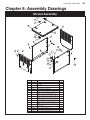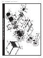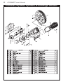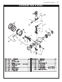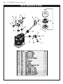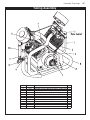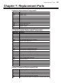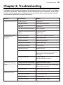
1
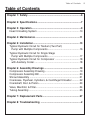
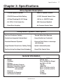
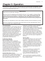
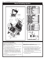
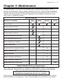
MODEL SHD-66DD
OWNER’S MANUAL
Safety • Operation • Installation • Maintenance
Subject to Change without Notification.
© 2014 American Eagle.
American Eagle, Inc.
740 N. State Street
PO Box 169
Garner, IA 50438
800-392-3015
Fax: 641-923-9099
www.americaneagleacc.com
Last Revision: 05/28/14
ii
AE Compressor Manual Revisions
AE SHD66DD Owner’s Manual
Date of Revision
Section Revised
Description of Revision
August 2013
All Sections
Updated to new style compressor
May 2014
Assembly Drawings
Updated to new shroud design
Introduction
Introduction
American Eagle Compressors are designed to
provide safe and dependable service for a
variety of operations. With proper use and
maintenance, American Eagle Compressors will
operate at peak performance for many years.
This manual contains information vital to the
safe use and efficient operation of this unit.
Following the information provided within this
manual can ensure the longevity of the
compressor. Carefully read and study the
operator’s manual before using the unit. Failure
to adhere to the instructions could result in
property damage or even serious bodily injury to
the operator or others close to the compressor.
A copy of this manual is provided with every
compressor and shall remain with the
compressor at all times. Information contained
within this manual does not cover all
maintenance, operating, or repair instructions
pertinent to all possible situations. This manual
is not binding. American Eagle reserves the
right to change, at any time, any or all of the
items, components, and parts deemed
necessary for product improvement or
commercial/production purposes. This right is
kept with no requirement or obligation for
immediate mandatory updating of this manual.
This product manual is not intended as a
training manual for beginners or unskilled
operators. This manual offers guidelines for
correct and safe usage of the compressor,
maintenance, and troubleshooting. If more
information is required or technical assistance is
needed, please contact AE Technical Support.
Some sections of this manual contain
information pertaining to all American Eagle
manufactured compressors and may or may not
apply to your specific model.
If this manual becomes damaged, misplaced, or
unreadable at any point, or if you feel that any
part of this manual is unclear or incorrect,
please contact AE Technical Support at 800321-3741 or email at
[email protected]
For Technical Questions, Information, Parts, or Warranty, Call Toll-Free at
800-321-3741
Hours: Monday - Friday, 8:00 a.m. - 5:00 p.m. CST
Or email at the following addresses:
Technical Questions, and Information
Order Parts
Warranty Information
1
[email protected]
[email protected]
[email protected]
2
AE SHD66DD Owner’s Manual
Table of Contents
Table of Contents
Chapter 1: Safety .............................................................................5
Chapter 2: Specifications ...............................................................7
Chapter 3: Operation.......................................................................9
Head Unloading System .............................................................10
Chapter 4: Maintenance ................................................................11
Chapter 5: Installation...................................................................13
Typical Hydraulic Circuit for Tandum (Two Part)
Pump with Multiple Components..............................................16
Typical Hydraulic Circuit for Single Stage
Pump with Multiple Components..............................................17
Typical Hydraulic Circuit for Compressor ...................................18
with Auxiliary Cooler .................................................................18
Chapter 6: Assembly Drawings ...................................................19
Compressor Assembly Drawing ..................................................19
Compressor Assembly Bill ..........................................................20
Shroud Assembly ........................................................................21
Crankcase, Flywheel, Cylinders, & Centrifugal Unloader ...........22
Crankshaft, Rod, & Piston...........................................................23
Valve, Manifold, & Filter...............................................................24
Tubing Assembly .........................................................................25
Chapter 7: Replacement Parts .....................................................27
Chapter 8: Troubleshooting ..........................................................2
3
4
AE SHD66DD Owner’s Manual
Chapter 1: Safety
Safety
5
This manual contains vital information for the safe use and efficient
operation of this unit. Carefully read the operators manual before
starting the unit. Failure to adhere to the instructions could result in
serious bodily injury or property damage.
The SHD-66DD Hydraulic Air Compressor will
provide safe and dependable service if operated
according to instructions. Read and understand
the safety precautions given in this manual and
on the decals attached to the shields. Failure to
do so can result in personal injury or equipment
damage.
Operators and maintenance personnel must
always comply with the safety precautions.
These precautions are given here for your
safety. Review them carefully before operating
the compressor and before performing
maintenance or repairs.
Supervising personnel should develop additional
precautions relating to the specific work area
and local safety regulations.
Precautions
Always wear safety equipment such as goggles,
ear plugs and head protection at all times when
operating the compressor.
Do not inspect or clean the compressor while
the hydraulic power source is connected.
Accidental engagement of the tool can cause
serious injury.
Before performing any maintenance on the
compressor, place a warning tag on the
hydraulic power source or disconnect the hoses
from the compressor motor to prevent
accidental startup of the compressor.
Always connect hoses to the compressor before
energizing the hydraulic power source. Be sure
all hose connections are tight, both air and
hydraulic.
Establish a training program for all operators to
ensure safe operation.
Do not operate the compressor unless
thoroughly trained or under the supervision of
an instructor.
Do not operate the compressor if it is damaged,
improperly adjusted or not completely or
properly assembled.
Never operate the compressor with any of the
guards removed.
Do not attempt to adjust or disable the
compressors air pressure relief valve. This
valve limits the air pressure to 175 PSI.
The surface of the air compressor and the
plumbing between the compressor and the
cooler may reach temperatures above 150
degrees. Touching these surfaces during
operation can cause burns.
The air taken in by the air compressor must be
free of flammable fumes and vapors.
Compressor speed should not exceed 1000
RPM.
Use and operate this air compressor only in full
compliance with all pertinent O.S.H.A.
requirements and all Federal, State and Local
codes or requirements.
6
AE SHD66DD Owner’s Manual
Chapter 2: Specifications
Specifications
Drive System Description
• 18 GPM Hydraulic System
• 2200 PSI System Pressure
• All Steel Plumbing W/ JIC Fittings
• 165 Sq. In., 300 BTU Cooler
• 2700 PSI Pressure Relief Setting
• 12 VDC Solenoid Control Valve
• 861 CFM, 12 Volt Cooler Fan
• 6061 Aluminum Manifold
• Direct Drive Coupling
• Air Pressure Control Valve
Compressor System Description
• Cast Iron Crankcase Casting
• Tapered Roller Main Bearings
• Precision Balanced Flywheel
• Pressure Relief Valves in interstage
and discharge
• Gasket-free Integrated Cylinder/Head
• Heavy Ductile Iron Crankshaft
• Large Diameter Finned Inner Cooling Tubing
• Positive Acting Centrifugal Head Unloaders
•
•
•
•
•
•
•
• Splash Lubricated System
• Preset Pilot Control Valve
General Information
Model:
Weight:
Cylinders:
Delivery:
Maximum Working Pressure:
Maximum Compressor Speed:
Dimensions: (w/o reservoir)
(w/ reservoir)
• Electrical:
• Crankcase Oil Capacity:
• Oil Reservoir Capacity:
Champion R30D
425 lbs. (dry)
Four Cylinder(Two Stage)
46 CFM @ 175 PSI
175 PSI
1000 RPM
33.5”L x 23.5”W x 25.5”H
48.5”L x 23.5”W x 25.5”H
12 VDC
4 Quart
16 Gallons
SHD-66DD Manual
7
8
AE SHD66DD Owner’s Manual
Chapter 3: Operation
Operation
9
Each compressor is bench tested under load at the factory to ensure proper break-in and operation. While it
is not necessary to follow any break-in procedure, the following checks should be made before putting the
unit into service and periodically during use.
Inspect unit for any visible signs of damage.
Before Start-Up
Check the oil level in the compressor with the dipstick on the unit. If oil is needed, use American Eagle
synthetic compressor oil (P/N C0087) or an equivalent synthetic oil. Note: There may be oil left in the
crankcase from the factory bench test. Overfilling may cause the compressor to back blow oil.
Always check the oil level and fill to the designated marking on the dipstick before putting the unit
into service.
Check hoses (air and hydraulic) for weak or worn condition and make sure that all connections are secure.
Check the air intake filters on each head to make certain that they are clean and unobstructed. Dirty air
filters are a possible cause of reduced air output.
General Information
To use the compressor, start the vehicle engine and
engage the hydraulic system. The compressor can
now be activated using the compressor switch. This
energizes the hydraulic solenoid sending oil to the
hydraulic drive motor and starts the compressor.
Through the air pressure switch and pilot valve, the
system will now function automatically. Once
engaged, adjust the engine speed control to ensure
that the compressor speed does not exceed 1000
RPM under load. Adjustment instructions are
provided with the speed control unit.
Air Pilot Valve Operation
(Head Unloading System)
When the hydraulic system is engaged the
compressor will pump air into the receiver until the
pressure reaches 175 psi. At this time the air pilot
valve senses the pressure in the receiver and
engages an intake valve hold-open mechanism.
The compressor will run free until the pressure in
the receiver falls below 145 psi and the air pressure
valve disengages the intake valve hold-open
mechanism to allow the compressor to pump air.
See head unloading system for detailed views and
adjustment instructions on the next page.
Hydraulic Motor Bypass Circuit
The hydraulic motor is equipped with a bypass circuit
which protects the compressor from over speed.
When the compressor is pumping, all hydraulic oil
flows through the hydraulic motor. When the
compressor is running free, some oil is bypassed
around the hydraulic motor preventing the
compressor from speeding up until the engine speed
control disengages. The bypass circuit, in conjunction
with the engine speed control will cause the
compressor to turn very slowly when not pumping.
This is normal operation. When air is again required,
the engine speed control engages, the bypass circuit
closes and the compressor will operate at speed. The
bypass circuit is set at the factory, no adjustment is
necessary.
Operating Notes:
This reciprocating compressor must not be used for
breathing air. To do so will cause serious injury
whether air is supplied direct from the compressor
source or to breathing tanks for later use. Any and
all liabilities for damage or loss due to injuries, death
and/or property damage, including consequential
damages stemming from the use of this compressor
to supply breathing air will be disclaimed by the
manufacturer.
The use of this compressor as a booster pump
and/or to compress a medium other than
atmospheric air is strictly non-approved and can
result in equipment damage and/or injury. Nonapproved uses will also void the warranty.
Never use plastic pipe or improperly rated metal
pipe. Improper piping materials can burst and cause
injury or property damage.
10
AE SHD66DD Owner’s Manual
Head Unloading System
Intake Valve
Hold-Open
Mechanism
C
A
(Route to Air Pilot Valve)
Air Pilot Valve Adjustment
(See Air Pilot Valve Adjustment Detail)
High Pressure Adjustment: Proceed with the following
while the compressor is running.
1.) Loosen locknut (D) and back off several turns. Do
not turn differential adjuster (C).
2.) Check reading on the tank pressure gauge. Set the
compressor maximum pressure at 175 psi. Over
pressurizing compressor will cause damage and
void warranty. Turn threaded cap (A) clockwise to
increase pressure or counterclockwise to decrease
pressure.
3.) After pressure is set, tighten locknut (D). Be careful
not to move the threaded cap (A).
D
B
Differential Pressure Adjustment: Proceed with the
following while the compressor is running.
1.) Loosen locknut (B) and back off several turns.
2.) Check reading on the tank pressure gauge. Set the
pressure to 30 psi differential (unload at 175 psi,
reload at 145 psi). Turn nut (C) clockwise to
increase differential pressure or counterclockwise to
decrease differential pressure.
3.) After pressure is set, tighten locknut (B). Be careful
not to move nut (C)
Chapter 4: Maintenance
Maintenance
11
The following table is a list of routine maintenance items, including service intervals. Service
intervals are listed as hours, days, or weeks, whichever occurs first. American Eagle recommends
that these service intervals be followed. Before performing any maintenance function “Lock Out” or
“Tag Out” all sources of power. Be sure all air pressure in unit is relieved. Failure to do so may
result in injury or equipment damage.
Maintenance operation
Drain air tanks
Service Intervals
Daily
Weekly
Monthly
Hourly
Check crankcase oil level
Check fittings and airlines
Check hydraulic fluid level
Inspect and clean air intake filters
Clean and operate safety valves
Clean cooling fins on radiator
Inspect check valve
Inspect and clean compressor valves
6
Replace air filters
3
Replace hydraulic filter
Tighten all fittings and fasteners
Check all electrical connections
Inspect and clean air check valve
CHANGE CRANKCASE OIL (see footnote below)
6
3
3
250
Under normal operating conditions, oil changes are required every 3 months. When operating in a
dirty environment, change the oil more frequently as your particular operating condition dictates.
USE AE SYNTHETIC COMPRESSOR OIL P/N C0087.
COMPRESSOR CRANKCASE CAPACITY IS 4 QUARTS.
General preventative maintenance includes maintaining proper fluid level in both systems and the
general cleanliness of the equipment. Proper fluids according to the specifications are required.
12
AE SHD66DD Owner’s Manual
Chapter 5: Installation
Installation
13
COMPONENT INSTALLATION
This section pertains to the installation of the air compressor, PTO, pump and other related items.
The instructions are intended as a guide to assist you with particular installation. These instructions
will provide only general information.
Pump Assembly:
The pump assembly may either be installed
directly on the PTO or as an optional method,
may be driven by a driveline from the PTO.
Pump manufacturers provide specific installation
information for their products and should be
consulted if questions arise.
PTO Assembly:
Check with the PTO manufactures
representative for specific instructions regarding
your particular make, model, and year of vehicle.
As some trucks may require modification of the
transmission cross member and the exhaust
system, the manufacturer’s instructions should
be followed to insure proper installation of the
PTO.
Compressor Assembly:
Prepare the mounting location of the compressor
by locating and drilling four (4) holes, 9/16”
diameter as per the mounting pattern of the air
compressor base. Using four (4) 1/2” x 1.50”
GR-5 cap screws, 1/2” flat washer, and 1/2”
nyloc nut, secure the compressor in place. The
compressor is air cooled, and must have a clean
supply of cooling air to the fan with minimum
restrictions. Adequate space must be provided
for proper circulation of air.
Electric speed control:
An optional electric or electronic speed control
must be used to maintain proper operating
speed of the air compressor. The engine speed
control will automatically increase from idle to a
preset speed when engaged and decrease when
disengaged.
14
Component Installation Continued...
AE SHD66DD Owner’s Manual
Pilot Air From
Air Tank
Compressed Air
Supply
Case Drain
Connect Directly Tank
Hydraulic Return
To Tank
Hydraulic Supply
From Pump
Electrical Connection
Crank Case Drain
Component Installation Continued...
Installation
Stellar
Supplied
Reservoir
Connect 1-1/4” Suction Hose
to 1-1/4” Barb Fitting.
Motor case drain
routed to hydraulic
reservoir
1/2” High Pressure
Hydraulic Hose
Length as Required
Note: There are (2) Locations
that you can Plumb the
Sunction Hose (Side and Bottom)
1-1/4” Hydraulic Suction Hose
Length as Required
Adapter as
Required to
Fit Your Pump
1-1/4” Barb/Adapter
to Fit Your Pump
Hydraulic Pump
Hydraulic System:
Installed on the compressor are bulkhead fittings to which hydraulic lines are attached. To the
appropriate fitting (see drawing detailing front of compressor), a 1/2” high-pressure hose must be
attached. This hose comes from the hydraulic pumps pressure side. A 1-1/4” hydraulic suction hose
must be installed from the hydraulic reservoir to the hydraulic pump. (See drawing above) Note: For
compressors purchased without a reservoir a 3/4” minimum low-pressure return line is connected to
the hydraulic return fitting and is routed to the oil reservoir through a filter. The case drain line from
the hydraulic motor is also routed to the oil reservoir (DO NOT INSTALL A FILTER ON THE CASE
DRAIN LINE). American Eagle recommends a sufficient sized reservoir be provided which includes
the proper suction and return filters. The cooler on the compressor is designed and sized to cool the
air compressor efficiently. An auxillary oil cooler is required when additional hydraulically operated
equipment are added to the hydraulic system. Pressure on the return line exceeding 200 PSI can
and will cause damage to the filter, cooler, and components of the compressor hydraulic system.
See Detail A
See Detail B
NO
C
Detail A
Detail B
NC
3/4” Hose
Air Line
To Air Tank
1/4” Hose
Air Sense Line
to Air Tank
Check Valve
Air System:
Two (2) airlines must be routed to the air tank for
proper installation. The main airline is routed from the
check valve to the air tank using a 3/4”(200psi) air
hose. This is the main delivery line and should be free
from all obstructions. A 1/4” line is routed from the air
pressure valve to the air tank. This line senses the
pressure in the tank and will engage and disengage
the compressor automatically.
15
16
AE SHD66DD Owner’s Manual
Typical Hydraulic Circuit for Single Stage Pump with
PN 30533
Multiple Components
Typical Hydraulic Circuit for Tandum
(Two Part) Pump with
PN 30532
Multiple Components
Installation
Typical Hydraulic Circuit for Compressor
with Auxiliary Cooler
HYDRAULIC
RESERVOIR
FILTER
FILTER SCREEN
AUXILIARY
COOLER
SUCTION PORT
SINGLE
HYDRAULIC
PUMP
COMPRESSOR
RETURN
PRESSURE
17
18
AE SHD66DD Owner’s Manual
Chapter 6: Assembly Drawings
Assembly Drawings
Shroud Assembly
11
6
5
8
3
17
12
1
14
1
4
6
5
15
16
15
2
13
15
14
6
7
14
14
15
5
6
ITEM
1
PART
65875
2
69517
3
4
5
6
65877
19589
19592
C6021
7
70473
8
70474
9
70379
10
70379
11
69101
12
73654
13
73653
14
15
16
17
D0917
0333
70475
73724
D E SCRI PTION
QTY.
PANEL SIDE SHD66 SHROUD BH PC WHITE
1
PANEL FRONT SHD66 SHROUD BULKHEAD
1
PC WHITE
PANEL REAR SHD66 SHROUD PC WHITE
1
NUT SERT 0.25-20X0.38 OD
16
WASHER 0.25 FLAT NYLON
22
CAP SCR 0.25-20X0.75 BTNHD SS
26
PANEL SIDE RH SHD66 SHROUD BH V3 PC
1
WHITE
PANEL LID CPRSR SHD66 SHROUD PC
1
WHITE
HINGE ZINC BLK FLUSH SURFACE MNT DC1
50-P8
HINGE ZINC BLK FLUSH SURFACE MNT DC1
50-P8
LATCH SWING LEVER FLUSH TRIGGER 0.912
1.81
BRKT LID GASPROP CPRSR SHROUD V2 PC
2
WHITE
BRKT LOWER GASPROP CPRSR SHROUD
2
V2 PC WHITE
WASHER 0.25 FLAT SS
18
NUT 0.25-20 HHGR5 NYLOC
18
GAS SPRING 7.50-12.00 60# FORCE
2
WEATHERSTRIP RIBBED 0.38X0.13X117.00
1
10
19
58
13
12
53
27
41
56
35
4
2
46
17
43
4
9
29
8
34
23
64
37
7 11
29
31
57
21 50
16
55 30
44
25
33
27
26
58
72
18
48
47
42
74
22
15
6
45
19
14
71
75
29
63
5
70
5
3
66
22
54
15
60
49
68
51
40
32
73
15
64
36
69
28
6
17 17
20
62
24 11
65
10
67
6
60
Compressor Assembly Drawing
20
56
39
64
11
7
17
61
1
38
64
59
52
20
AE SHD66DD Owner’s Manual
19645
20884
22183
22186
24304
26025
28855
57195
65746
32
33
34
35
36
37
38
39
20326
20330
20459
29
30
31
28
B
PART
0279
0333
0335
0340
0347
0351
0359
0479
052 1
052 3
0525
1554
1556
3 854
4581
4703
5290
5418
5480
7351
8277
1 0 65 9
12813
16711
18611
19589
19592
ITEM
1
2
D 3
4
5
6
7
8
9
10
11
12
13
14
15
C 16
17
18
19
20
21
22
23
24
25
26
27
DE SCR IP T IO N
FTG 6-6 MFS-MORB STRAIGHT
NUT 0.25-20 HHGR5 NYLOC
CAP SCR 0.38-16X1.25 HHGR5
WASHER 0.25 USS FLAT ZINC
NUT 0.38-16 HH NYLOC
CAP SCR 0.38-16X1.00 HHGR5
CAP SCR 0.50-13X1.50 HHGR5
CAP SCR 0.25-20X0.75 HHGR5
W A S H E R 0 . 25 LO CK
WA S H E R 0 . 3 8 LO CK
WAS HER 0 . 5 0 L OCK
FTG 8-8 MFS-MORB STRAIGHT
FT G 8 - 8 M F S- M A O R B 9 0
F TG ST L 4 5 DE G 44- 2 05
N I P PL E 0 . 7 5 X 4 . 00 B R A S S
BRKT UNLOADER VALVE MNT SHD66DD
WASHER #8 SAE FLAT ZINC
ST EL 0.25 90 DEG BRASS 44-161
VALVE CHECK 0.75 STANDARD
FTG ST TH ELBOW 45 DEG 12V5OLO
FTG ST L 0.25 MNPT/0.125 FNPT SPL
C PLR 0 .75 B RAS S
GROMMET 1.25ODX0.125X0.625ID
FTG 0.75-TEE BRASS 80101-12
SCREW #6-32X0.38 HH MACH SELF TAP
NUT SERT 0.25-20X0.38 OD
WASHER 0.25 FLAT NYLON
BRKT MOTOR MOUNT 19645
POWDERCOAT
PLUG 0.25 NPT SQ HD BRASS
FTG 0.38-0.25 FF HEX NIPPLE
N I P P L E 0 . 3 8 X 8 . 00 B R A S S
FTG 12-12X6.00 MP-MP NIPPLE STRAIGHT
BRASS
SCREW #8-32X0.75 BTNHD SS
NU T #8-32 HH NYLOC S S
CAP SCR 0.25-20X3.00 BTNHD SS
CAP SCR 0.50-13X2.25 HHGR5
HOUR METER 12VDC TST 180-1911
MOTOR HYD RSB04K-Y4500-A 4.0 CID
HOSE 0.75(200PSI)-12FFSS SHORT-12FFSS
90 SHORT 11.5 OAL
1
2
2
2
2
1
1
1
4
1
1
1
Q TY.
1
2
2
4
8
10
8
2
2
4
10
1
1
1
3
1
8
1
1
2
1
2
1
1
2
1
7
69515
69643
70144
70385
71406
C0081
C 086 4
C1129
C1180
C2142
C4941
C5662
C5968
C601 5
C6021
C6106
C6353
D0075
D0076
D0786
D0790
D0791
D0792
D0793
D0824
D0840
D0847
D0 8 5 6
D1254
D1266
D1299
D1346
45
46
47
48
49
50
51
52
53
54
55
56
57
58
59
60
61
62
63
64
65
66
67
68
69
70
71
72
73
74
75
42
69516
69514
41
44
69513
40
43
P ART
65873
ITEM
DESCRIPTION
Q TY.
BASE WLDMT SHD66DD ENCLOSURE
1
BULKHD
MANIFOLD CPRSR SHD66 BULKHEAD
1
TUBE ASM 0.50 PRESSURE SHD66
1
BULKHEAD YZ
TUBE ASM 0.75 RETURN SHD66 BULKHEAD
1
YZ
BRKT BULKHEAD MOUNT SHD66
1
TUBE ASM 0.38 DRAIN SHD66 BULKHEAD
1
YZ
VALVE SOLND W/ RELIEF 12V SVRV10-26B1
0-N-12DW
SHROUD ASM SHD66 BULKHEAD V3
1
FTG HOSE 4-4 PL-MP STRAIGHT BRASS
1
C LAMP 0.50 BLK VINYL
1
S W I T C H P RE S H O B B S
1
COOLER OIL 24 GPM MAX FLOW
1
FTG ADAPT 8-12 F5OLO-S
1
FTG 12-12 MFS-MORB STRAIGHT
1
CLAMP MUFFLER 1 1/8
1
FILTER METAL BOWL 0.25
1
FTG 12-12 MFS-MAORB 90
2
F T G 0 . 75 P L U G 1 2 - P 5 O N
1
CAP SCR 0.25-20X0.75 BTNHD SS
7
NUT 0.50-13 HHGR5 NYLOC
2
WASHER 0 .38 FLAT GR8
8
SCREW #6-32X2.75 RH HD MACHINE
2
NUT #6-32 HH NYLOC
2
BRKT WLDMT COOLER MNT LH SHD66DD
1
WAS H E R 0 .50 F LAT G R 8
12
COUPG 1/4 KW L150-0.75
1
COUPG 3/8 KW L150-1.75
1
COUPG SPIDER L150-U BLUE URETHANE
1
BRKT WLDMT COOLER MNT RH SHD66DD
1
FAN 12.00 PUSH 12 VOLT SPL 301003
1
BRKT 11.00 TWIST 45 DEG SHD66DD
1
B R KT L I F T SH D 6 6 DD
1
CAP 0.38 PIPE HEX 5406-CAP-6
1
FTG 12-12 FP-FP 90 BRASS
1
FTG BULKHEAD 6WLO-WLNL-S
1
CPRSR CHMP R30DHU SPECIAL
1
Compressor Assembly Bill
Assembly Drawings
21
22
AE SHD66DD Owner’s Manual
Crankcase, Flywheel, Cylinders, & Centrifugal Unloader
Crankshaft, Rod, & Piston
Assembly Drawings
23
24
AE SHD66DD Owner’s Manual
Valve, Manifold, & Filter
Tubing Assembly
ITEM
1
2
3
4
5
6
7
8
9
10
11
12
PART No.
7473
7474
7475
7476
7477
7476
7478
D1873
D1872
5592
5593
7479
Assembly Drawings
DESCRIPTION
TUBE FITTING
RELEASE VALVE TUBE W/FITTINGS (ITEMS 1&3)
TUBE FITTING
TUBE FITTING
BREATHER TUBE W/FITTINGS
(ITEMS 4&6)
TUBE FITTING
TUBE, DISCHARGE
INTERCOOLER TUBE W/FTGS RH
INTERCOOLER TUBE W/FTGS LH
TUBE, DISCHARGE
TUBE FITTING
PIPE TEE
qty
1
1
1
1
1
1
1
1
1
1
2
1
25
26
AE SHD66DD Owner’s Manual
Chapter 7: Replacement Parts
Replacement Parts
Hydraulic Replacement Components
Part Number
Description
61792
57195
Hydraulic valve
Hydraulic motor
C1129
C2029
Oil cooler
O-ring #8 face seal
D1244
O-ring #12 face seal
D1247
O-ring #8 SAE port seal
D1249
O-ring #12 SAE port seal
C6226
Hydraulic filter head
C6227
Hydraulic oil filter
16145
Filter gauge
Air End & Assembly Replacement Components
Part Number
Description
D1346
R30 Compressor air pump
7471
Valve assembly (Low pressure intake)
C0891
Valve assembly (Low pressure exhaust)
7472
Valve assembly (High pressure Intake)
C0894
Valve assembly (High pressure exhaust)
4558
Complete valve gasket set
4557
Complete valve set with / Gaskets
32895
Valve assembly kit (Includes both valves 7471 & 7472 only)
7417
Muffler assembly unloader
C0896
Release valve kit assembly
D1873
Intercooler tube w/Fittings (Right hand)
D1872
Intercooler tube w/Fittings (Left hand)
D0786
Cooler Mount Bracket (Left hand)
D0824
Cooler Mount Bracket (Right hand)
D0791
Coupling (Hydraulic motor)
D0792
Coupling (Compressor)
D0793
Lovejoy coupling (Blue urethane)
C0864
Air pressure switch
3853
Pilot valve 145/175 psi
5480
Check valve
D0840
Fan 12 volt
C5662
Metal filter bowl w/Filter
Service Component Replacement Parts
Part Number
Description
4559
Air filter
6073
Intake filter assembly (Housing & filter)
C0087
Synthetic compressor oil (1 quart)
7259
Synthetic compressor oil (Case) 12 quarts
8825
Service kit (Includes air filters, compressor oil, hyd filter & filter bowl)
27
28
AE SHD66DD Owner’s Manual
Chapter 8: Troubleshooting
Troubleshooting
29
If symptoms of poor performance develop, the following chart can be used as a guide to investigate
and correct the problem. When diagnosing faults in operations of the air compressor, always check
that the hydraulic power source is supplying the correct hydraulic flow and pressure that is listed in
the compressor specification section of this manual.
Problem
Compressor will not start:
Possible Cause
Solution
Emergency brake off.
Fully engage parking brake.
PTO not engaged.
Blown fuse.
Loose or broken power/ground wire.
Compressor runs slow or
slows down during
operation:
Repair connection.
Loose air lines or hoses.
Tighten air lines and hose connections.
Hydraulic motor worn.
Replace with new motor.
Hydraulic flow too low.
Faulty compressor valves.
Pilot valve leaking air.
Centrifugal unloader valve leaking.
Hydraulic oil temp high.
Compressor runs hot:
Replace fuse.
Compressor manifold solenoid will not Repair wiring to coil.
Replace valve.
engage.
Hydraulic relief set too low.
Compressor will lock up
after operating for a short
period:
Engage PTO.
Check and reset flow.
Readjust relief valve.
Clean or replace.
Replace pilot valve.
Remove the governor release valve cap, giving
access to the unloader pressure release valve
spring and ball - Clean thoroughly and
reassembly.
Hydraulic fluid low.
Hydraulic reservoir size incorrect.
Hydraulic motor drive coupler loose.
Reposition and tighten coupler.
Faulty check valve.
Clean or replace check valve.
Faulty hydraulic relief valve.
Remove relief valve, inspect o-rings and backup
seals or replace relief valve.
Dirty after cooler or intercooler tubing. Remove and clean.
Faulty compressor values.
Clean or replace valves.
Low crankcase oil level.
Add compressor oil as needed.
Dirty intake muffler.
Clean or replace.
30
AE SHD66DD Owner’s Manual
Problem
Compressor will not shut
down:
Possible Cause
Solution
Misadjustment of pilot valve.
Adjust valve per manual specifications.
Air line or air hose leaks.
Pilot valve leaking air
Centrifugal unloader valve is leaking.
Moisture or rust contamination.
Tighten air lines or hose connections.
Clean or replace pilot valve.
See “Compressor runs slowly” section.
Remove filter bowl. Fill with WD40 lubricant.
Open air tank valve. Run compressor for 10
minutes. Partially close air tank valve and cycle
compressor. Repeat as needed.
Compressor continues to
build air during idle mode:
Faulty low pressure intake valve.
Compressor will not speed
up when compressor is
activated:
Air reservoir full.
Drain air from reservoir.
No 12 volt power to coil solenoid
valve located on hydraulic manifold.
Check fuse. Check ground wires. Check
chassis emergency brake switch.
Engine RPM will not
increase when compressor
is activated:
Leaking or misadjustment of the pilot
valve.
Faulty pressure switch.
Loose wiring.
Faulty pressure switch.
Faulty speed control.
Compressor cycles or runs
often:
Faulty pressure switch.
Excessive water in air reservoir.
Pip lines leaking air.
Misadjustment of pilot valve.
Air leaking from pilot valve.
Check valve leaking.
Faulty pressure switch.
Chassis engine RPM
continue to operate at high
Pressure switch wiring.
speed when air receiver
reaches maximum capacity:
Clean or replace low pressure intake valves.
Tighten or adjust valve per manual specs.
Test for 12 volt power on both the “C” and “NC”
side of the terminals. If no power on “NC” side
of pressure switch, replace switch.
Check wiring to : Solenoid valve, pressure
switch, ground wiring.
Replace pressure switch.
Check speed control wiring for loose or broken
connections. Check relay (For ECM operated
speed settings.)
Replace pressure switch.
Drain air reservoir.
Tighten or replace lines.
Adjust valve per manual specifications.
Clean, adjust, or replace.
Clean or replace.
Replace pressure switch.
Wires place on pressure switch incorrectly or
loose ground wire.
31
4-91+)5 )/3- >)99)5;: 796,<+;: ,-:1/5-, )5, 4)5<.)+;<9-, *@ ";-33)9 ;6 *- .9-- .964 ,-.-+;: 15 4);-91)3 )5, >6924)5:017 <5,-9 7967-9 <:- )5,
4)15;-5)5+- 96,<+;: 4<:; *- 15:;)33-, )5, 67-9);-, 15 )++69,)5+- >1;0 ";-33)9B: >91;;-5 15:;9<+;165: )5, +)7)+1;1-: #0- >)99)5;@ 7-916, :0)33 +6=-9
;0- .6336>15/
#>-3=#>-3=-
465;0 >)99)5;@ 65 7)9;: )5,
465;0 9-7)19 3)*69
1.-;14- >)99)5;@ 65 :31,-: )5, 0)9,>)9#0- >)99)5;@ 7-916, :0)33 *-/15 .964 ;0- ,);- 9-+69,-, *@ 4-91+)5 )/3- ): ;0- 15 :-9=1+- ,);- #01: ,);- >133 *- ,-91=-, .964 ;0- +6473-;-,
>)99)5;@ 9-/1:;9);165 +)9, 5 ;0- -=-5; ) >)99)5;@ 9-/1:;9);165 +)9, 1: 56; 9-+-1=-, *@ 4-91+)5 )/3- ;0- .)+;69@ :017 ,);- >133 *- <:-, ->
+6479-::69: >133 *- 1::<-, 65 )33 9-;<95: >1;015
,)@: 6. ;01: .)+;69@ :017 ,);.;-9
,)@: 4-91+)5 )/3- 9-:-9=-: ;0- 91/0; ;6 1::<9-4)5<.)+;<9-, +6479-::69: !-/)9,3-:: 6. 15 :-9=1+- ,);- >)99)5;@ +6=-9)/- ,6-: 56; -?;-5, *-@65, ;>-5;@ .6<9
465;0: .964 ,);- 6.
4)5<.)+;<94-91+)5 )/3-B: 6*31/);165 <5,-9 ;01: >)99)5;@ 1: 3141;-, ;6 )5, ;0- :63- 9-4-,@ .69 )5@ :<+0 ,-.-+; :0)33 *- ;0- 9-7)19 )5, 69 9-73)+-4-5; );
4-91+)5 )/3-B: 67;165 6. ;0- <5)3;-9-, 7)9; )5, 69 +64765-5; 15 8<-:;165 4-91+)5 )/3- ).;-9 :)3-: :-9=1+- 7-9:655-3 4<:; *- 56;1.1-, *@
;-3-7065- .)? 69 3-;;-9 6. )5@ >)99)5;@ )7731+)*3- ,)4)/- >1;015 .6<9;--5
,)@: 6. 1;: 6++<99-5+- . ); )33 76::1*3- 4-91+)5 )/3- >133 :017 ;09-73)+-4-5; 7)9; >1;015
06<9: 6. 56;1.1+);165 *@ ;0- 46:; -+65641+)3 @-; -?7-,1-5; 4-)5: 76::1*3- ?7-,1;-, .9-1/0; ,-31=-9@ >133 *- ); ;0-?7-5:- 6. ;0- 6>5-9
&)99)5;@ +3)14: 4<:; *- :<*41;;-, )5, :0)33 *- 796+-::-, 15 )++69,)5+- >1;0 4-91+)5 )/3-B: -:;)*31:0-, >)99)5;@ +3)14 796+-,<9- 4-91+)5
)/3- ).;-9 :)3-: :-9=1+- 7-9:655-3 4<:; *- +65;)+;-, 79169 ;6 )5@ >)99)5;@ +3)14 9-;<95 4);-91)3: )<;0691A);165 !
)++6<5; 5<4*-9 4<:; *1::<-, ;6 ;0- +3)1415/ 7)9;@ 79169 ;6 ;0- 9-;<95 6. )5@ >)99)5;@ 7)9;: )9;: 9-;<95-, >1;06<; 79169 )<;0691A);165 >133 56; *- 9-+6/51A-, .69 >)99)5;@
+65:1,-9);165 33 ,)4)/-, 7)9;: 4<:; *- 9-;<95-, ;6 4-91+)5 )/3- .9-1/0; 79-7)1, .9-1/0; +633-+; 9-;<95: >133 *- 9-.<:-, 9-1/0; 9-14*<9:-4-5; 6.
9-;<95-, 7)9;: >133 *- +65:1,-9-, ): 7)9; 6. ;0- >)99)5;@ +3)14
&)99)5;@ :-9=1+- >133 *- 7-9.694-, *@ )5@ 4-91+)5 )/3- 5-> -8<174-5; ,1:;91*<;69 69 *@ )5@ 4-91+)5 )/3- 9-+6/51A-, :-9=1+- +-5;-9 )<;0691A-,
;6 :-9=1+- ;0- ;@7- 6. 796,<+; 15=63=-, 69 *@ ;0- 4-91+)5 )/3- .)+;69@ 15 ;0- -=-5; 6. ) ,19-+; :)3- ; ;0- ;14- 6. 9-8<-:;15/ >)99)5;@ :-9=1+- ;06>5-9 4<:; 79-:-5; -=1,-5+- 6. ,);- 6. ,-31=-9@ 6. ;0- 796,<+; #0- 6>5-9 :0)33 *- 6*31/);-, ;6 7)@ .69 )5@ 6=-9;14- 3)*69 9-8<-:;-, 6. ;0- :-9=1+15/
+647)5@ *@ ;0- 6>5-9 )5@ .1-3, :-9=1+- +)33 +0)9/-: )5, )5@ ;6>15/ )5, 69 ;9)5:769;);165 +0)9/-: )::6+1);-, >1;0 46=15/ ;0- -8<174-5; ;6 ;0,-:1/5);-, 9-7)19 :-9=1+- 796=1,-9
33 6*31/);165: 6. 4-91+)5 )/3- )5, 1;: )<;0691A-, ,-)3-9: )5, :-9=1+- 796=1,-9: :0)33 *- =61,-, 1. :64-65- 6;0-9 ;0)5 )5 )<;0691A-, 4-91+)5 )/3,-)3-9 796=1,-: 6;0-9 ;0)5 96<;15- 4)15;-5)5+- :-9=1+- >1;06<; 79169 >91;;-5 )7796=)3 .964 4-91+)5 )/3- 5 ;0- +):- 9-7)19 >692 1: 7-9.694-, 65 )
4-91+)5 )/3- 4)5<.)+;<9-, 796,<+; 691/15)3 4-91+)5 )/3- 7)9;: 4<:; *- <:-, ;6 2--7 ;0- >)99)5;@ 15 .69+- #0- >)99)5;@ 4)@ )3:6 *- =61,-, 1.
;0- 796,<+; 1: 46,1.1-, 69 )3;-9-, 15 )5@ >)@ 56; )7796=-, 15 >91;15/ *@ 4-91+)5 )/3#0- 6>5-9 67-9);69 1: 9-:765:1*3- .69 .<951:015/ 7966. 6. ;0- ,);- 6. 691/15)3 7<9+0):- 6. ;0- 4-91+)5 )/3- 796,<+; 15 8<-:;165 &)99)5;@ 9-/1:;9);165
1: ;0- <3;14);- 9-:765:1*131;@ 6. ;0- 6>5-9 )5, 4)@ *- )++64731:0-, *@ ;0- +6473-;165 )5, 9-;<95 6. ;0- 4-91+)5 )/3- 796,<+; 9-/1:;9);165 +)9,
796=1,-, >1;0 ;0- 796,<+; . ;0- 6>5-9 1: 56; :<9- 6. 9-/1:;9);165 0- 1: -5+6<9)/-, ;6 +65;)+; 4-91+)5 )/3- ); ;0- ),,9-:: *-36> ;6 +65.194
9-/1:;9);165 6. ;0- 796,<+; 15 8<-:;165 #01: >)99)5;@ +6=-9: 653@ ,-.-+;1=- 4);-91)3 )5, >6924)5:017 ; ,6-: 56; +6=-9 ,-79-+1);165 69 ,)4)/- +)<:-,
*@ 5694)3 >-)9 )5, ;-)9 )++1,-5; 41:0)7 <5;9)15-, 67-9);69: 69 147967-9 69 <515;-5,-, <:- #0- 6>5-9 0): ;0- 6*31/);165 6. 7-9.69415/ 96<;15+)9- )5, 4)15;-5)5+- ,<;1-: ): :;);-, 15 4-91+)5 )/3-B: >91;;-5 15:;9<+;165: 9-+644-5,);165: )5, :7-+1.1+);165: 5@ ,)4)/- 9-:<3;15/ .964
6>5-9 67-9);69 .)13<9- ;6 7-9.694 :<+0 ,<;1-: :0)33 =61, ;0- +6=-9)/- 6. ;01: >)99)5;@ #0- 6>5-9 >133 7)@ ;0- +6:; 6. 3)*69 )5, :<7731-: )::6+1);-, >1;0
96<;15- 4)15;-5)5+#0- 653@ 9-4-,1-: ;0- 6>5-9 0): 15 +655-+;165 >1;0 ;0- *9-)+0 69 7-9.694)5+- 6. )5@ >)99)5;@ 65 ;0- 4-91+)5 )/3- 796,<+; :7-+1.1-, )9- ;06:- :-;
)*6=- 5 56 -=-5; >133 4-91+)5 )/3- ;0- 4-91+)5 )/3- ,1:;91*<;69 ,-)3-9 69 )5@ +647)5@ )..131);-, >1;0 4-91+)5 )/3- *- 31)*3- .69 *<:15-::
15;-99<7;165: +6:;: 6. ,-3)@ 69 .69 )5@ :7-+1)3 15,19-+; 15+1,-5;)3 69 +65:-8<-5;1)3 +6:;: 69 ,)4)/-: "<+0 +6:;: 4)@ 15+3<,- *<; )9- 56; 3141;-, ;6
36:: 6. ;14- 36:: 6. 9-=-5<- 36:: 6. <:- >)/-: :)3)91-: +6441::165: 36,/15/ 4-)3: ;6>15/ 0@,9)<31+ .3<1, 69 )5@ 6;0-9 15+1,-5;)3 +6:;
33 796,<+;: 7<9+0):-, *@ 4-91+)5 )/3- .964 6<;:1,- =-5,69: :0)33 *- +6=-9-, *@ ;0- >)99)5;@ 6..-9-, *@ ;0); 9-:7-+;1=- 4)5<.)+;<9-9 653@
4-91+)5 )/3- ,6-: 56; 7)9;1+17);- 15 69 6*31/);- 1;:-3. ;6 )5@ :<+0 >)99)5;@
4-91+)5 )/3- 9-:-9=-: ;0- 91/0; ;6 4)2- +0)5/-: 15 ,-:1/5 69 14796=-4-5; <765 1;: 796,<+;: >1;06<; 1476:15/ <765 1;:-3. ;0- :)4- <765 1;:
796,<+;: ;0-9-;6.69- 4)5<.)+;<9-,
#01: >)99)5;@ >133 )773@ ;6 )33 4-91+)5 )/3- 9)>-9 "-;: )5, 6479-::-, 19 "@:;-4: :0177-, .964 4-91+)5 )/3-B: .)+;69@ ).;-9 <3@
>)99)5;@ 1: .69 ;0- <:- 6. ;0- 691/15)3 6>5-9 653@ )5, 1: 56; ;9)5:.-9)*3- >1;06<; 79169 >91;;-5 7-941::165 .964 4-91+)5 )/3# " & !! #( " ' ! "" (
!
#
#( ! # ""
# !
" !%
" ""
" $ #
"
!-=1:165
);-
)@
$
!
(
!# $
!
# ! & !! # "
! $! " !
!
' ! "" !
$
"$
! # " & !! #( !
$"#! "
"
#! "
"
( & !! #(
#
# #
! %"
!
#
!
6+<4-5;
<4*-9
#0-