1
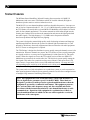
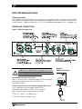
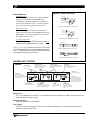
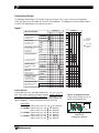
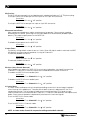
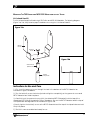
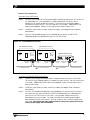
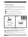
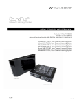
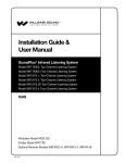
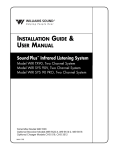
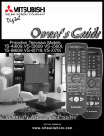
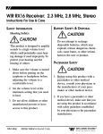
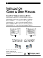
INSTALLATION
GUIDE & USER MANUAL
SOUNDPLUS™ INFRARED LISTENING SYSTEM
Model WIR TX925, Two-Channel Listening System
Model WIR TX900, Four-Channel Listening System
Model WIR SYS 1, Two-Channel Listening System
Model WIR SYS 2, Two-Channel Listening System
Model WIR SYS 2P, Two-Channel Listening System
Model WIR SYS 4, Four-Channel Listening System
Williams Sound
Two Channel Infrared System Modulator
Microprocessor Controlled
Frequency Synthesized
Power
4 5 6
3
2
1
0
10
Level
7
8
9
3.8
+9
+6
+3
0
-3
-6
-9
-12
-15
-18
3.3
Compress
2.8
2.3
Frequency
(MHz)
4 5 6
3
2
1
0
10
Level
7
8
9
+9
+6
+3
0
-3
-6
-9
-12
-15
-18
Inputs Mixed
3.8
3.3
Compress
2.8
2.3
Phones
IR
CH A
Williams
Microprocessor Controlled
Frequency Synthesized
4 5 6
Power
3
2
1
0
Frequency
(MHz)
CH B
10
Level
7
8
9
+9
+6
+3
0
-3
-6
-9
-12
-15
-18
Frequency
(MHz)
Sound
Compress
4 5 6
3
2
1
0
10
Level
7
8
9
+9
+6
+3
0
-3
-6
-9
-12
-15
-18
3.8
3.3
Inputs Mixed
Phones
Compress
2.8
Stereo
2.3
Frequency
(MHz)
IR
CH A
CH B
Channel B
Williams Sound
IR
IR
4 channel
el
4 chann
Williams
Sound
IR
el
4 chann
Modulator Model MOD 232
Emitter Model WIR TX9
Optional Receiver Models WIR RX12-4,
WIR RX14-2
MAN 102F
Williams Sound
3.8
3.3
2.8
2.3
Channel A
Channel B
Channel A
Two Channel Infrared System Modulator
Stereo
Williams Sound
IR
4 channel
®
Williams
Sound
Helping People Hear
SOUNDPLUS™ INFRARED LISTENING SYSTEM,
Model WIR TX925, Two-Channel Listening System
Model WIR TX900, Four-Channel Listening System
Model WIR SYS 1, Two-Channel Listening System
Model WIR SYS 2, Two-Channel Listening System
Model WIR SYS 2P, Two-Channel Listening System
Model WIR SYS 4, Four-Channel Listening System
INSTALLATION GUIDE AND USER MANUAL
Contents
SYSTEM OVERVIEW
Page
4
INSTALLATION PROCEDURES
• MOD 232 MODULATOR SETUP
WIRING & CONNECTIONS
FEATURES & CONTROLS
CONFIGURATION SETTINGS
• TX9 EMITTER SETUP
LOCATION / PLACEMENT
COVERAGE AREA
MOUNTING
WIRING & CONNECTIONS
FEATURES & CONTROLS
• RECEIVER SAFETY INSTRUCTIONS
• RECYCLING INSTRUCTIONS
• RX12-4 RECEIVER SETUP
TROUBLESHOOTING
5
7
9
12
13
17
22
25
26
26
27
29
LANGUAGE INTERPRETATION
IC-1 CONSOLE
WARRANTY
30
31
SPECIFICATIONS
• MOD 232 MODULATOR
32
• MODEL TX9 EMITTER
33
• RX12-4 RECEIVER
34
• WIR RX14-2 RECEIVER
34
Williams
Sound ®
Helping People Hear
3
SYSTEM OVERVIEW
The Williams Sound SoundPlus™ Infrared Listening System consists of a MOD 232
Modulator(s) and one or more TX9 Emitters which use invisible infrared (IR) light to
broadcast speech or music to wireless infrared receivers.
The MOD 232 is a two-channel modulator with four selectable frequencies. It accepts two
mic or line-level inputs and sends 2.3, 2.8, 3.3, or 3.8 MHz frequency synthesized signals to
the TX9 Emitter via coaxial cable (a second MOD 232 Modulator can be added via coaxial
cable for four-channel application). The emitter transmits invisible infrared light into the
listening area. Infrared receivers detect the transmission and convert the light signals back
into audio signals. The high frequency 2.3-3.8 MHz carrier frequencies minimize
interference problems from high efficiency lighting.
The system is designed to transmit high quality audio for hearing assistance and language
translation applications. Because the system uses infrared light for transmission, it is not
affected by interference from radio equipment and does not interfere with radio equipment.
No FCC license or radio approval is required.
The TX9 Emitter is designed to distribute its power equally among the channels sent to it for
transmission. When two channels are present, the TX9 divides its power equally among the
two signals to achieve a coverage area of approximately 18,000 square feet (1,700 square
meters). When four signals are sent to the TX9 (which can occur when two MOD 232
Modulators are connected via coaxial cable), the TX9 divides its power equally among the
four signals. This makes for a practical coverage area of about 11,000 square feet (1,022
square meters). Larger areas can be covered with additional emitters. Coverage area will
vary depending on the sensitivity of the infrared receiver being used and reflections and
absorption of the IR signal in the listening area.
The system can be used with microphones as a stand-alone system, or can be connected to
other sound equipment. Infrared systems generally cannot be used in direct sunlight because
of sunlight’s large amount of interfering infrared light.
Note: This equipment has been tested and found to comply with the limits for a
Class A digital device, pursuant to part 15 of the FCC Rules. These limits are
designed to provide reasonable protection against harmful interference when the
equipment is operated in a commercial environment. This equipment generates,
uses, and can radiate radio frequency energy and, if not installed and used in
accordance with the instruction manual, may cause harmful interference to radio
communications. Operation of this equipment in a residential area is likely to
cause harmful interference in which case the user will be required to correct the
interference at his own expense.
4
Williams
Sound ®
Helping People Hear
MOD 232 Modulator Setup
DETERMINE LOCATION
The modulator is usually located with the sound system amplifier or mixer for easy access to an audio
input signal. For portable systems, the modulator can be placed near the emitter or in another convenient location. Infrared Stand Kits (SS-6, SS-10, SS-11) are available for portable systems. See pages 19-21.
WIRING AND CONNECTIONS
Figure 1: MOD 232 (Rear View)
WARNING: POWERLINE VOLTAGE MUST NOT
FALL BELOW 94V, OR SYSTEM PERFORMANCE
WILL BE GREATLY REDUCED!
POWER CONNECTION FOR U.S. APPLICATION
Step 1: Connect the TFP 016 power supply to the 3-pin MolexTM
connector located on the rear of the MOD 232.
(See Figure 2, right.)
FOR APPLICATIONS OUTSIDE THE U.S. REQUIRING 240 VAC MAINS SUPPLY:
Use the transformer power supply, model TFP 027.
Secondary specifications: 24 VAC, 35 VA, 50/60 Hz.
Step 2: Plug the power supply into the AC outlet.
Figure 2:
Power Connection
m Modulator
lliams Sound
Power In
24 VAC, 15 VA, 50-60 Hz
Plug
24V
Power In Jack
TFP 027-01: 230VAC, Euro Mains Plug
TFP 027-02: 230VAC, UK Mains Plug
Williams
Sound ®
Helping People Hear
5
BASEBAND CABLE CONNECTION
The MOD 232 can directly drive one or two emitters. TX9 emitters repeat the baseband signal, so
any number of emitters can be used. The modulator outputs CANNOT be split with CATV splitters.
Determine the length of RG-58 cable needed to reach from the TX9 Emitter to the Modulator unit.
Install BNC connectors to each end of the cable (see page 24 for installation details).
For two-channel application, only one MOD 232 is required: Connect the coaxial cable to one of
the Baseband Output jacks on the rear of the MOD 232. The other end of the coaxial cable
connects to the Baseband Input jack of the TX9 Emitter. See Figure 3 below.
Figure 3: Baseband Connection, Two Channel Application
MOD 232 Modulator (Rear)
Input CH A
Input CH B
CH A
12345678
MOD 232 Infrared System Modulator
Audio Line
Output
Williams Sound
Input
CH A
CH B
Baseband
Output
Output
(Second TX9 Optional)
Power In
12345678
24 VAC, 15 VA, 50-60 Hz
Configuration
Switches
Plug
CH B
100 Ohms
Made in USA
50 Ohms
24V
Baseband
Output
Baseband
Output
To TX9
Baseband Input
To TX9
Baseband Input
Connect to the TX9 using RG-58 cable and BNC connectors. The MOD 232 has two baseband
output jacks to simplify connections when multiple emitters are used.
To setup a system for four-channel operation, two MOD 232 Modulators are required. Link the two
Modulator units together. Connect the WCA 068 coaxial cable (supplied with the SoundPlus™
Infrared Listening System) to one of the Baseband Output Jacks in the rear of the first MOD 232 in the
chain. The other end of the coaxial cable connects to the Baseband Input Jack of the second
MOD 232 in the chain. Then connect the baseband output from the second modulator in the chain
to the TX9 emitter(s) baseband input connector. See Figure 4 below.
Figure 4: Baseband Connection, Four Channel Application
MOD 232 Modulator #1 (Rear)
Input CH A
Input CH B
CH A
12345678
Input CH A
Williams Sound
Input
Baseband
Output
CH A
50 Ohms
24V
Baseband
Output
Output
Power In
24 VAC, 15 VA, 50-60 Hz
Plug
CH B
Made in USA
Baseband
Output
Williams Sound
Input
12345678
Configuration
Switches
Plug
CH B
100 Ohms
12345678
CH A
CH B
24 VAC, 15 VA, 50-60 Hz
MOD 232 Infrared System Modulator
Audio Line
Output
Input CH B
Output
Power In
12345678
Configuration
Switches
Made in USA
MOD 232 Infrared System Modulator
Audio Line
Output
CH A
CH B
MOD 232 Modulator #2 (Rear)
Baseband
Input
Coaxial Cable
(WCA 068)
100 Ohms
50 Ohms
24V
Baseband
Output
To TX9 Emitter
Baseband Input
IMPORTANT: Each channel must be set to a different frequency.
6
Williams
Sound ®
Helping People Hear
Figure 5: Audio Connection
AUDIO CONNECTION
MICROPHONE INPUT:
With the modulator DIP switches set for microphone
input, the 3-pin XLR jack accepts balanced
microphones. Power for condenser microphones
can be selected by DIP switch. The minimum input
level is 100uV and the maximum level is 90 mV.
In Phase
1
2
3
3 Pin Connector
Balanced Line Using 3–Pin Connector
XLR LINE-LEVEL INPUT:
With the modulator DIP switches set for line-level
input, the 3-pin XLR jack accepts balanced line-level
audio inputs. The minimum input level is 21mV and
the maximum level is 10uV.
1
3 Pin Connector
2
3
Unbalanced Line Using 3–Pin Connector
1/4” TRS LINE-LEVEL INPUT:
The 1/4” Tip/Ring/Sleeve (TRS) jack can accept only
a balanced or unbalanced line-level input.
In Phase
A 25 V, 70 V, or 100 V speaker line can be connected
to the balanced line input using an appropriate attenuator. “T” pads made with resistors yield better fidelity
than speaker matching transformers.
Balanced Line Using 1/4' Connector
Unbalanced Line Using 1/4" Connector
FEATURES AND CONTROLS
Figure 6
Compress Control
Increases transmitted audio
up to 30 dB during periods of low
level sound.
Carrier (CXR) LEDs
4 green LED "on" indicators
per channel. Indicates selected
frequency, malfunctions.
Level Controls
Controls level of
audio signal.
Two Channel Infrared System Modulator
Power Switch
Turns the modulator
on and off. The associated
wall mounted power supply
stays on at all times.
Microprocessor Controlled
Frequency Synthesized
Power
4 5 6
3
2
1
0
10
Level
7
8
9
+9
+6
+3
0
-3
-6
-9
-12
-15
-18
Williams Sound
3.8
3.3
2.8
2.3
Frequency
(MHz)
Compress
4 5 6
3
2
1
0
7
8
9
10
Level
Channel A
Power On Indicator
Indicates operation of unit.
Inputs Mixed
Indicates CH A & CH B
audio are mixed and transmitted
by CH A. CH B is off.
Level Indicators
Bar graph level indicator shows
audio level in 3 dB steps at input of
audio level processing circuit.
+9
+6
+3
0
-3
-6
-9
-12
-15
-18
3.8
3.3
2.8
2.3
Frequency
(MHz)
Stereo LED
Indicates Stereo Mode
Inputs Mixed
Compress
Phones
Stereo
IR
CH A
CH B
Channel B
IR LED
Infrared receivers can
be tested using the IR
LED.
Phones Jack
1/4" phone jack. Monitors
Channel A or Channel B or
stereo audio depending on
position of phone jack switch,
and mode of operation.
Phones Switch
Push button selects
Channel A or Channel B
audio when not in stereo
mode.
POWER SWITCH
Turns the modulator on and off. The associated wall mounted power supply stays on at all times
and may operate continuously.
POWER ON INDICATOR
Indicates operation of modulator.
LEVEL CONTROL
Controls level of audio signal. The control is connected between the input amplifier and the
audio level processing circuit.
Williams
Sound ®
Helping People Hear
7
LEVEL INDICATOR
The bar graph indicator shows audio level in 3dB steps at the input of the audio level processing
circuit. The indicator is peak responding and is calibrated so that optimum level is reached
when the amber +3 and +6 lights usually blink and the red +9 light blinks occasionally. Use the
level controls to set the audio levels.
FREQUENCY (CARRIER)
Channel A and B have four “on” indicators to designate 2.3, 2.8, 3.3, or 3.8 MHz frequency. The
carrier comes on when power is applied, but goes off automatically if there is no audio for
approximately 30 minutes. Audio sufficient to light the -18 level indicator will reset the timer,
allowing for another 30 minutes of no audio before the carrier shuts off again. This timer can be
disabled. See pages 9, 11. The operating frequency for each channel is selected by DIP switches.
COMPRESS CONTROL
The Compress Control increases transmitted audio up to 30 dB during periods of low level sound.
To increase compression, use a tuning wand (PLT 005) or small screw driver and gently turn the
compression pot clockwise. The compression slope can be adjusted from 1:1 (no compression)
to 4:1 (substantial compression).
Compression is used for hearing assistance applications to reduce dynamic range.
Compression is not normally used in language interpretation application. Note: The modulator
has been pre-set for minimum compression. Refer to page 11 for an explanation of compressor
settings on the MOD 232.
PHONES
The phones jack monitors the transmitted audio signal. If the modulator is operating in two
channel mode, Channel A or Channel B can be selected for monitoring. If the modulator is
operating in stereo mode, the jack produces a stereo output. Use the phones jack to verify the
quality of the transmitted audio.
PHONES SWITCH
Push-button selector to monitor Channel A or Channel B audio when not in stereo mode.
INPUTS MIXED LED
Indicates Channel A and Channel B audio are mixed and transmitted by Channel A. Channel B
carrier is off.
STEREO LED
Indicates stereo mode. Audio processing (compression, limiting) are coupled and adjusted by
the Channel A compression adjust. Channel frequencies are forced to 2.3 and 2.8 or 3.3 and 3.8.
IR LED
The IR LED transmits a short range (about 1 meter) infrared signal. Infrared receivers can be
tested using the infrared LED. The signal emitted from this LED is modulated by the carriers
generated in this unit only. If this smodulator is connected to other modulators for additional
channels, their carriers are not emitted by the LED, and must be monitored at those modulators.
8
Williams
Sound ®
Helping People Hear
CONFIGURATION SETTINGS
The diagram below (Figure 7) illustrates how to configure your system using the configuration
switches (Figure 8) on the back of the MOD 232 Modulator. This diagram is also printed on top of
the MOD 232 Modulator unit for quick reference.
Figure 7
CHANNEL B
CHANNEL A
SWITCH SETTINGS
1
2
3
4 5
6 7
8
1
2
3
4 5
6 7
8
COMPRESSOR GAIN
SETS MAXIMUM AVAILABLE
COMPRESSOR GAIN
MAXIMUM
Arrow up
indicates on
position
MODERATE
MIC/LINE INPUT
LINE ALWAYS ON 1/4 INCH
MIC OR LINE ON 3 PIN
LINE
Arrow down
indicates off
position
MIC
MICROPHONE SIMPLEX POWER
15 VOLTS PER DIN 45596
NOT AVAILABLE IN
LINE INPUT MODE
OFF
ON
CARRIER FREQUENCY
3.800 MHz
3.300 MHz
DO NOT SET BOTH CHANNELS
TO THE SAME FREQUENCY
2.800 MHz
2.300 MHz
CHANNEL ENABLE
TURNS CHANNEL OFF WHEN
DISABLED
ENABLED
DISABLED
MIX INPUTS
AVAILABLE ONLY IN ONE
CHANNEL OPERATION
NOT MIXED
MIXED
2 CHANNEL/STEREO
IN STEREO MODE, CHANNEL A
COMPRESSION SETTING
CONTROLS BOTH CHANNELS
NON-STEREO
STEREO
AUTO SHUT-OFF TIMER
TURNS CARRIER(S) OFF AFTER 30
MINUTES OF NO AUDIO
DISABLED
ENABLED
CARRIER FREQUENCY
Choose between four selectable frequencies: 2.3, 2.8, 3.3, or 3.8
MHz. Select one frequency for each channel. MAKE SURE EACH
CHANNEL IS SET TO A DIFFERENT FREQUENCY. To operate in fourchannel mode, two MOD 232 units will need to be installed (see
Figure 4, page 6). To select a frequency on the MOD 232:
Figure 8: Configuration Switches
Adjust switch settings on rear of
MOD 232 Modulator here:
Input CH A
Instructions:
For 2.3 MHz: Place switch 4 & 5 in the “off” position.
For 2.8 MHz: Place switch 4 in the “on” position,
Place switch 5 in the “off” position.
For 3.3 MHz: Place switch 4 in the “off” position,
Place switch 5 in the “on” position.
For 3.8 MHz: Place switch 4 in the “on” position,
Place switch 5 in the “on” position.
Williams
Sound ®
Helping People Hear
Input CH B
CH A
CH B
12345678
12345678
Configuration
Switches
Made in USA
CH A & CH B
Configuration Switches
9
MIC/LINE INPUT
The MOD 232 only accepts line level balanced or unbalanced inputs on 1/4” TRS phone plug.
To setup the MOD 232 to accept line level inputs on the 3 pin XLR connector:
Instructions:
Place switch 2 in the “off” position.
To setup the MOD 232 to accept mic input on 3 pin XLR connector:
Instructions:
Place switch 2 in the
“on” position.
MICROPHONE SIMPLEX POWER
Most condenser microphones require simplex power to operate. Power can be supplied
according to DIN 45596. (Selecting line-level input above will automatically disable simplex
power.) To enable simplex power on the MOD 232:
Instructions:
Place switch 3 in the
“on” position.
To disable simplex power on the MOD 232:
Instructions:
Place switch 3 in the
“off” position.
CHANNEL ENABLE
The factory setting of both channels are on. Note: When Mix Inputs mode is selected, the MOD
232 defaults to single channel operation, turning off Channel B.
To manually disable a channel:
Instructions:
Place switch 6 in the
“on” position.
To manually enable a channel:
Instructions:
Place switch 6 in the
“off” position.
MIX INPUTS (SINGLE CHANNEL OPERATION)
Mixing audio inputs places the MOD 232 in one-channel operation, turning off the carrier for
Channel B. Channel A & Channel B inputs are mixed and transmitted on Channel A.
To enable the MOD 232 to mix audio inputs:
Instructions:
Place switch 7 on Channel A in the
“on” position
To disable the MOD 232 to mix audio inputs:
Instructions:
Place switch 7 on Channel A in the
“off” position
2 CHANNEL/STEREO
In stereo mode, audio processing is coupled, providing a consistent stereo image, important
when listening with headphones. Compression for both channels is adjusted with the CH A
compression control. The left channel audio source should feed Input CH A and the right
channel audio source should feed Input Channel B. 2 Channel mode provides mono processed
audio. Each channel operates independently and transmits two mono signals.
To set the MOD 232 in stereo mode:
Instructions:
Place switch 7 on Channel B in the
“on” position
To set the MOD 232 in 2 Channel mode:
Instructions:
Place switch 7 on Channel B in the
“off” position
NOTE: In stereo mode, Channel A compression setting controls both channels.
10
Williams
Sound ®
Helping People Hear
AUTO SHUT-OFF TIMER
The carriers for each channel shut off automatically if there is no audio for approximately 30
minutes. Audio sufficient to the light the -18 level indicator light will turn the carrier back on
immediately. To disable the auto shut-off timer on the MOD 232:
Instructions:
Place switch 8 in the
“off” position.
To enable the auto shut-off timer on the MOD 232:
Instructions:
Place switch 8 in the
“on” position.
In stereo mode, the timers operate together.
COMPRESSOR GAIN
The MOD 232’s Compressor Gain is set in “Moderate” mode from the factory. Use this setting for
simultaneous interpretation. Be sure that the compress pot control, located on the front of the
MOD 232 (Figure 6, page 7), is turned fully counter-clockwise. Compression can be added if
desired by turning the compress pot control clockwise.
For hearing assistance applications, the MOD 232’s Compressor Gain can be set to “Maximum”
mode. For additional compression, use a tuning wand (PLT 005) or small screw driver and gently
turn the compress pot (Figure 6, page 7) on the front of the MOD 232 clockwise.
The difference between “Moderate” and “Maximum” Compressor Gain is illustrated below:
Figure 9
LEVEL INDICATOR
—18—15—12—9 —6 —3 0 +3 +6 +9
0 dB
IO
RAT
MIN COMPRESSION,
MAX AND MODERATE GAIN
-10 dB
MAX COMPRESSION,
MODERATE GAIN
MAX COMPRESSION,
MAX GAIN
COMPRESSION
ADJUSTMENT RANGE
WITH MODERATE GAIN
-20 dB
-30 dB
1:
1
C
O
M
PR
ES
SI
O
N
R
AT
I
O
COMPRESSION
ADJUSTMENT RANGE
WITH MAX GAIN
RELATIVE OUTPUT LEVEL
(0 dB = MAXIMUM MODULATION)
ION
ESS
MPR
1 CO
4.3:
-40 dB
-30 dB
-20 dB
-10 dB
0 dB
+10 dB
+20 dB
RELATIVE INPUT LEVEL
(REFERENCE TO LEVEL METER)
To setup the MOD 232 for “Moderate” Compressor Gain:
Instructions:
Place switch 1 in the
“on” position.
To setup the MOD 232 for “Maximum” Compressor Gain:
Instructions:
Place switch 1 in the
Williams
Sound ®
Helping People Hear
“off” position.
11
TX9 EMITTER SETUP
TX9 LOCATION AND PLACEMENT
To determine the best location for the TX9 Emitter, it helps to think of the IR emitter as an invisible
floodlight. You’ll want to aim it so the listeners are “flooded” with the infrared light. The emitter should
also be positioned high enough so it won’t be blocked by people and other physical obstructions.
Mount the emitter at least 2 ft. (.61 m) above the audience.
Position the emitter to face in a slightly downward angle - that will increase the “throw” of the infrared
beam. Infrared light reflects off most surfaces and scatters, increasing the coverage area. Rough
surfaces tend to absorb infrared light, minimizing reflections, and limiting coverage to the direct
illumination. Remember: opaque objects block infrared light. Thus, emitters cannot be concealed
behind opaque walls, curtains, etc.
The emitter front red plastic lens must NOT be painted. Neither should emitters be used in areas of
extreme high or low temperature, humidity, or chemical environments.
The TX9 Infrared Emitter should not be installed where there is a lot of direct sunlight, which can create
infrared interference.
Figure 10: NOTE: When pointing the emitter, be sure to keep the long dimension horizontal.
Correct
Incorrect
12
Williams
Sound ®
Helping People Hear
COVERAGE AREA
Determine the coverage area needed for the seating area. When using the TX9 emitter with the
RX12-4 receiver, in single channel mode, the TX9 can achieve a coverage area of 28,000 ft2 (2,600
m2 ). In four channel mode, the TX9 divides its power among the four signals to achieve a coverage
area of 11,000 ft2 (1,022 m2). NOTE: The coverage area will vary depending on the sensitivity of the
infrared receiver being used. The following diagram illustrates coverage area when using a RX12-4,
RX14, RX14-2, or RX16 receiver with a single TX9 emitter in single channel mode.
Figure 11: Maximum Range when using the RX12-4, RX14, RX14-2 or RX16 receiver
Feet 90
80
70
60
50
40
30
20
RX16
10
0
RX14
RX14-2
RX12-4
-10
-20
-30
-40
-50
-60
-70
-80
-90
Feet
0
10 20 30 40 50 60 70 80 90 100 110 120 130 140 150 160
Receiver Coverage Area with TX9
Transmitter in Single Channel Mode
RX12-4 Receiver
RX14 or RX14-2 Receiver
RX16 Receiver
These patterns are the direct radiation pattern. the infrared radiation does not drop to zero outside the
illustrated patterns; it decreases. It still may be useable at a greater distance, depending on the
receiver sensitivity and the reflective characteristics of the room.
Reflections of the infrared light from walls, ceilings, and floors may change these patterns.
Important: Remember to point the emitter towards the listening audience!
Remember: opaque objects block infrared light. Thus, emitters cannot be concealed behind opaque
walls, curtains, etc.
Williams
Sound ®
Helping People Hear
13
FIG 12: 3-Dimension Foot Pattern
The TX9 floods the listening audience with a
cone shape light pattern as shown here.
The path of the cone shape light leaves a
pattern on the ground, or "foot print, " and
indicates where the strongest receiver
reception will occur.
The actual coverage area will vary depending
on the sensitivity of the receiver being used.
Refer to Figures 11 and 14 to determine how
many emitters are required for 100% coverage
of the listening area.
To determine the best location for the emitter, it helps to think of the IR emitter as an invisible
floodlight. You’ll want to aim it so the listeners are “flooded” with the infrared light. The emitter
should also be positioned high enough so it won’t be blocked by people and other physical
obstructions. See Figure 13 below. Mount the emitter at least 2 ft. (.61 m) above the audience.
Position the emitter to face in a slightly downward angle, 20°, that will increase the “throw” of the
infrared beam.
FIG 13: Vertical Beam Spread
Minimum Receiver Range When Operating with a TX9 Emitter in Single Channel Mode
RX12-4 Receiver: 150' (45 m)
RX14-2: 80' (24 m)
RX16: 70' (21 m)
(Range)
TX9
r Beam
Emitte
Center Of
30'
SCREEN
6'
STAGE
14
Williams
Sound ®
Helping People Hear
FIG 14: Horizontal and Vertical Radiation Polar Plots
HORIZONTAL RADIATION POLAR PATTERNS
DISTANCE FROM EMITTER TO 1 nW/sq cm CONTOUR
180
48
160
42
140
36
120
30
24
– 70
– 60
– 50
– 40
– 30
100
80
60
200
54
180
48
160
42
140
36
120
30
FEET
54
– 90
– 80
METERS
200
FEET
METERS
– 90
60
VERTICAL RADIATION POLAR PATTERNS
DISTANCE FROM EMITTER TO 1 nW/sq cm CONTOUR
– 80
– 70
– 60
– 50
– 40
– 30
100
24
80
18
60
12
40
6
20
– 20
18
60
12
40
6
20
– 20
– 10
– 10
0
0
10
10
20
20
30
30
40
40
50
50
60
60
70
90
80
70
90
80
1 Channel, 1 nW/sq cm
(Approx. 28000 sq ft, 2600 sq m)
1 Channel, 1 nW/sq cm
2 Channel, 1 nW/sq cm per channel
(Approx. 18000 sq ft, 1700 sq m)
2 Channels, 1 nW/sq cm per channel
4 Channel, 1 nW/sq cm per channel
(Approx. 11000 sq ft, 1000 sq m)
4 Channels, 1 nW/sq cm per channel
Reflections of the infrared light from walls, ceilings, and floors may change these patterns.
Important: remember to point the emitter towards the listening audience!
If you’re not getting sufficient coverage with a single, properly installed TX9 Emitter, you’ll need to
add additional emitters to achieve full coverage of your listening area (see page 16, Using Multiple
Emitters). Figures 15a and 15b illustrate how multiple emitters can be used for large room
installations.
Williams
Sound ®
Helping People Hear
15
Multiple Emitters Installed to Maximize Coverage
FIG. 15a: Overlapping Illumination Patterns to Cover Larger Listening Areas
TX9
TX9
TX9
TX9
Fig. 15a above is a typical example of how multiple emitters are used to cover larger listening
areas. Generally it is desirable for the illumination patterns to overlap. Note: The coverage area will
vary depending on the infrared receiver being used; refer to Figures 11 and 14 to determine how
many emitters are required to achieve full coverage of a listening area.
FIG. 15b: Overlapping Illumination Patterns to Cover Larger Listening Areas
Coverage Area
with Single Emitter
TX9
TX9
Coverage Area
with Second Emitter
Added to Same
Emission Point
(50% increase)
When two emitters are used at the same emission point in single channel mode, the overall
coverage area increses 50%. When using an RX12-4 receiver, as a result, the coverage area will
increase to an estimated 42,000 ft2 (3,902 m2); the RX14-2 will increase to 5,250 ft2 (488 m2); the RX16
will increase to 4,590 ft2 (426 m2 ).
16
Williams
Sound ®
Helping People Hear
MOUNTING THE TX9 TO A WALL OR CEILING
Figure 16a: Mounting the TX9 to a wall or ceiling with the BKT 024
TX9 Emitter
Swivel Head
Shaft
(optional)
Shaft
Plate
Cover
Mounting
Plate
(To Wall or Ceiling)
Mounting
Screws
Figure 16b: Mounting the TX9 to a ceiling cross tee with the BKT 024
TX9 Emitter
Swivel Head
Shaft
(optional)
Shaft
Plate
Cover
T-Bar
Clip
(To Suspended Ceiling
with Cross Tee)
**See page 18 for step-by-step installation instructions.
Williams
Sound ®
Helping People Hear
17
MOUNTING THE TX9 TO A WALL OR CEILING, STEP-BY-STEP:
Figure 17b
Figure 17a
Figure 17a:
Mounting the TX9 on to a wall with
the BKT 024.
Tip: To keep the TX9 level, rotate
the tension screw (Fig. 18) so it rests
of top of the bracket.
Figure 17b: Mounting the TXP on to
a ceiling witth the BKT 024
Step 1: Using the mounting plate (Figure 16a) as a template, mark the hole locations on the mounting
surface where the TX9 will be installed.
Step 2: Locate the top mounting hole in the rear of the TX9 emitter. See Figure 16. Gently screw the male end
of the swivel head on to the emitter. Tighten the tension screw (Figure 18): turn clockwise until
the connection is secure.
Step 3: Screw the male end of the shaft into the female end of the swivel head. An additional shaft can be
added to create more distance between the wall/ceiling and Emitter.
Step 4: Place the plate cover snugly over the mounting plate. This will hide the screws after installation.
Step 5: Screw the male end of the mounting plate into the female end of the shaft. For suspended ceilings,
screw the female end of the shaft into the male end of the T-Bar clip. The mounting bracket is now
installed on to the TX9 Emitter.
Step 6: Position the TX9 Emitter and BKT 024 so the mounting plate lines up with the marked holes on the mounting surface. Fasten the mounting plate to the surface using screws and wall anchors. Mounting the TX9
to a Suspended Ceiling with Cross Tee: Fasten the T-Bar clip (Figure 16b) on to the desired Cross Tee.
Step 7: Position the TX9 Emitter to the desired angle: Begin by gently turning the tension screw (Figure 18)
counter clockwise to release the swivel head. Adjust the TX9 to the desired angle. When the TX9 is in the
desired position, gently turn the tension screw clockwise until the swivel head is securely in place.
Figure 18: BKT 024
swivel
head
knob
The tension screw controls the action of the swivel head. To lock the swivel head into position,
turn the tension screw clockwise. To release the swivel head action, turn the tension screw counter clockwise.
18
Williams
Sound ®
Helping People Hear
MOUNTING THE TX9 EMITTER AND MOD 232 MODULATOR ON TO A TRIPOD
SS-6 Infrared Stand Kit
The SS-6 Infrared Stand Kit will hold a single TX9 Emitter and MOD 232 Modulator. The following diagrams
(Figures 19a, 19b, & 20) illustrates proper installation when using the SS-6 Infrared Stand Kit.
Figure 19a
BKT 014
Bracket
Butteryfly
Screw
Figure 19b
Grommet Screw
(Rubber Insert)
STD 004
Top of Tripod Tube
Instructions for Use and Care
1.) First, insert the grommet screw through the hole in the bottom of the BKT 014 bracket as
illustrated in Figure 19a above.
2.) Turn the butterfly screw clockwise (but do not tighten completely) so the grommet screw and
BKT 014 bracket are held into place.
3.) Carefully insert the grommet screw (with the attached BKT 014 bracket) into the top of the
tripod tube (STD 004) as illustrated in Figure 19a above. Be sure the BKT 014 bracket and the top of
the tripod tube are aligned flush as illustrated in Figure 19b.
4.) Lastly, tighten the butterfly screw so the BKT 014 bracket and the top of the tripod tube are held
firmly into place.
5.) The SS-6 is now assembled and ready for use.
Williams
Sound ®
Helping People Hear
19
SS-6 Infrared Stand Kit (cont.)
Figure 20: Installing the TX9 Emitter and MOD 232 Modulator on to the bracket
Infrared Emitter
TX8, TX9, TX10
Shoulder
Washer
Knob with
1/4"-20 screw
Infrared Modulator
WIR MOD 111, MOD 112, MOD 232
#6-32 X 3/8" Screws (4)
20
Williams
Sound ®
Helping People Hear
MOUNTING MULTIPLE TX9 EMITTERS ON TO A TRIPOD
SS-11 Infrared Stand Kit
The SS-11 Infrared Stand Kit can hold up to four TX9 Emitters at one time. The following diagram illustrates
proper installation when using the SS-11 Infrared Stand Kit.
Figure 21: Mounting the TX9 to the tripod crossbar
Knob
Extensions
(use as need be)
Ball and
socket
Crossbar
Top tube of tripod
Emitter
MOUNTING A SINGLE TX9 ON TO A MIC STAND
SS-10 Mic Stand Kit.
The following diagram illustrates proper installation when using the SS-10 Mic Stand Kit.
Figure 22
Locking Nut
Screws
L-Bracket
Emitter
Mic
Stand
Base
Williams
Sound ®
Helping People Hear
21
TX9 WIRING AND CONNECTIONS
FOR U.S. APPLICATIONS:
The TX9 Emitter is supplied with a low-voltage wall transformer power supply (TFP 010). Twoconductor 18 ga. zipcord is included with the emitter.
FOR U.S. APPLICATIONS OUTSIDE THE U.S. REQUIRING 240 VAC MAINS SUPPLY:
Use the transformer power supply, model TFP 027.
Secondary Specifications: 24 VAC, 35 VA, 50/60 Hz.
TFP 027-01, Euro Mains Cord
TFP 027-02, UK Mains Cord
WARNING: POWERLINE VOLTAGE MUST NOT FALL BELOW 94V,
OR SYSTEM PERFORMANCE WILL BE GREATLY REDUCED!
Step 1:
Determine the length of zip cord needed to reach from the transmitter to the AC
wall outlet where the power supply will be plugged in. If zip cord length will
exceed 200 feet (61 m), heavier gauge wire is required. Use the table below.
Make sure the power supply is not plugged into AC yet!
Cable Length Required
0 – 10 feet (3 m)
0 – 75 feet (23 m)
0 – 200 feet (61 m)
0 – 500 feet (152 m)
0 – 1000 feet (305 m)
Minimum Wire Gauge
22 gauge
20 gauge
18 gauge
16 gauge
14 gauge
One end of the zipcord has a 3-pin Molex connector, the other end is bare. Cut the
bare end of the zipcord to length. Separate the two conductor wires down the
middle approximately 1 inch, then strip both of the resulting strands about 1/8 inch.
For US installations, install the crimp-on spade terminals supplied. Connect these to
the screw terminals on the Power Supply. Polarity is not important since AC power
is being used.
Step 2:
Plug the 3-pin Molex connector into the TX9’s Power In connector (see Figure 25,
page 25).
Step 3:
Plug the Power Supply in last.
The Power Indicator LED on the right side of the bottom panel (visible from directly
underneath) glows when the TX9 is on.
Note:
The TX9 transmits when a baseband signal is present, and will shut off immediately
when no baseband signal is present. This auto shut-off feature preserves the life
of the infrared LEDs and reduces power consumption.
This system is designed for Class 2, low-voltage wiring. Always follow local electrical
codes when doing low voltage wiring.
22
Williams
Sound ®
Helping People Hear
BASEBAND CABLE CONNECTION
If you are using ONE emitter:
Step 1:
Determine the length of RG-58 coaxial cable needed to reach from the emitter to
the modulator unit. The modulator is usually located with the other sound
equipment to simplify audio connections. 100 feet (30 m) of coaxial cable is
included with each emitter. You will need to cut it to length. Additional RG-58
coax can be added. Make sure you leave some slack at each end.
Step 2:
Install BNC connectors on each end of the cable. (See page 24 for complete
description)
Step 3:
Connect the Baseband cable to the Baseband Out jack on the MOD 232
Modulator and to the Baseband In jack on the TX9 Emitter.
Figure 23: TX9 Baseband Connection
WIR TX9 Emitter #2 (Rear)
WIR TX9 Emitter #1 (Rear)
Multi-Channel Infrared Transmitter
Multi-Channel Infrared Transmitter
Williams
Sound ®
Helping People Hear
CAUTION
RISK OF ELECTRIC SHOCK
DO NOT OPEN
Power Supply Wiring:
Williams
Sound ®
Helping People Hear
CAUTION
RISK OF ELECTRIC SHOCK
DO NOT OPEN
Williams Sound Corp., Minneapolis, Minnesota, USA
WARNING: TO REDUCE THE RISK OF FIRE OR
ELECTRIC SHOCK DO NOT EXPOSE THIS
EQUIPMENT TO RAIN OR MOISTURE.
Note: It is normal for this unit to feel warm while it is in operation.
Williams Sound Corp., Minneapolis, Minnesota, USA
WARNING: TO REDUCE THE RISK OF FIRE OR
ELECTRIC SHOCK DO NOT EXPOSE THIS
EQUIPMENT TO RAIN OR MOISTURE.
Mounting
Bracket
Note: It is normal for this unit to feel warm while it is in operation.
Power Supply Wiring:
Use NEC, Class 2 Wiring, 18 ga. minimum,
200 ft. (70m) maximum length (18 ga.)
MOD 232 Modulator (Rear)
Mounting
Bracket
Use NEC, Class 2 Wiring, 18 ga. minimum,
200 ft. (70m) maximum length (18 ga.)
Baseband Signal Wiring:
Baseband Signal Wiring:
Use 50 Ohm Coaxial Cable (RG58)
Use RG58 Coax,1000 ft. (350m) max. length
Baseband Signal Wiring:
Baseband Signal Wiring:
Use 50 Ohm Coaxial Cable (RG58)
Use RG58 Coax,1000 ft. (350m) max. length
Input CH A
Class 1
LED Product
Class 1
LED Product
Made in U.S.A.
Power In:
24VAC
50-60Hz
35VA
~
Input CH B
CH A
12345678
24 VAC
Out
Plug
Out
In
50 Ohms
Power On
Baseband
(Modulation)
NC
Power In:
24VAC
50-60Hz
35VA
~
24 VAC
Out
Plug
Baseband On
Baseband
Output
To additional Emitters
Made in USA
Williams Sound
Input
Baseband
Output
Output
Power In
12345678
24 VAC, 15 VA, 50-60 Hz
Configuration
Switches
In
50 Ohms
Power On
Baseband
Input
Out
CH B
MOD 232 Infrared System Modulator
Audio Line
Output
CH A
Made in U.S.A.
Baseband
(Modulation)
NC
Plug
CH B
100 Ohms
50 Ohms
24V
Baseband On
Baseband
Output
To Second TX9 Emitter
Baseband
Input
Baseband
Output
To TX9 Emitter
Baseband
Output
To Additional Emiters
If you are using MORE THAN ONE emitter:
Step 1:
Determine the length of coaxial cable needed to reach between the emitters.
100 feet (30 m) of coaxial cable is included with each emitter. You will need to cut
it to length. Additional RG-58 coax can be added. Make sure you leave some
slack at each end.
Step 2:
Install BNC connectors on each end of the cable (See page 24 for complete
description)
Step 3:
Connect the baseband cable from the Baseband Out Jack on the first emitter in
the chain (the one connected to the MOD 232 Modulator) to the Baseband In
jack on the next TX9 Emitter in the chain. Use the cable clamps and screws
provided to secure the cable. The coax can also be routed through conduit
before attaching BNC connectors. You can chain as many emitters together as
you need. Remember that each emitter needs its own power supply and can not
share a power supply with a modulator.
Williams
Sound ®
Helping People Hear
23
24B
FIGURE 24A: BNC CONNECTOR ASSEMBLY
Washer
7.92 mm (± .25)
.312 in. (± .01)
Grooved Side
Nut
Gasket
Nut
Cable Jacket
Washer
Plug
Assembly
Gasket
24C
Clamp
Contact
Clamp positioned
against Cable Jacket
24D
ASSEMBLY PROCEDURE
Clamp Collar
The BNC Connector consists of a plug assembly, a
contact, a clamp, a gasket, a washer, and a nut.
1. Slide nut, washer and gasket over cable end;
then strip outer cable jacket using the recommended strip-length dimension in fig. 24b.
Clamp Braid folded
over Clamp and trimmed
24E
2. Slide clamp over cable braid and position it
against the cable jacket. After clamp is
properly positioned, comb out the braid.
3.96 mm (± .25)
.156 in. (± .01)
3. Fold cable braid over the clamp and trim it so
that it is positioned against the clamp collar.
See figures 24c and 24d.
4. Using the dimension in figure 24e, strip
dielectric to expose the center conductor. If
applicable, tin the center conductor.
Dielectric
24F
Dielectric
5. Solder contact to the conductor (using standard
soldering techniques), making sure contact is
bottomed on cable dielectric. See figure 24f.
DO NOT allow a hot soldering iron to touch
cable dielectric. Certain cable dielectric
materials, such as polypropylene, will expand
if they come in contact with a hot soldering
iron.
6. Insert contact into plug assemble until contact
snaps into place. See figure 24g.
7. Thread nut into plug assembly until it is secured.
Recommended cable clamp tightening torque is
2.8–3.4 N•m [25-30 in.-lb.], using a 7/16"
wrench. See figure 24h.
24
Contact soldered to conductor
and bottomed on dielectric
24G
Gasket (Ref.)
Contact Assembly
inserted into Plug
Assembly
Plug Assembly
24H
50 Ω BNC Plug Connector
Nut Secured Into
Plug Assembly
Williams
Sound ®
Helping People Hear
TX9 FEATURES AND CONTROLS
POWER INPUT
Three-pin connector for TFP 010 (110 VAC) or TFP 027 (for 240 VAC installations) power supply.
POWER INDICATOR LED
Visible through the bottom panel (Fig. 25). Green indicator light glows when power is on.
Note: The TX9 shuts off when no baseband signal is present.
BASEBAND INDICATOR LED
Visible through the bottom panel (Fig. 25). Red indicator light glows when power is on.
BASEBAND IN
Connects to the Baseband Out jack of the MOD 232 modulator or another TX9 emitter.
BASEBAND OUT
Connects to the Baseband In jack of the next TX9 emitter in the chain when multiple emitters are
used. There are two Baseband Output jacks to allow additional emitters to be connected.
WALL/CEILING MOUNTING BRACKET
An adjustable mounting bracket (BKT 024) is included with the emitter. An optional tripod stand
kit is also available. See pages 17-19.
Note: The WIR TX9 Infrared Emitter is a Class 1 LED product.
Figure 25: TX9 Emitter Rear View
Wall/Ceiling
Mounting Bracket (BKT 024)
Set of threaded holes for
use with mounting bracket.
Multi-Channel Infrared Transmitter
Williams
Sound ®
Helping People Hear
CAUTION
RISK OF ELECTRIC SHOCK
DO NOT OPEN
Williams Sound Corp., Minneapolis, Minnesota, USA
WARNING: TO REDUCE THE RISK OF FIRE OR
ELECTRIC SHOCK DO NOT EXPOSE THIS
EQUIPMENT TO RAIN OR MOISTURE.
Note: It is normal for this unit to feel warm while it is in operation.
Power Supply Wiring:
Mounting
Bracket
Use NEC, Class 2 Wiring, 18 ga. minimum,
200 ft. (70m) maximum length (18 ga.)
Baseband Signal Wiring:
Baseband Signal Wiring:
Use 50 Ohm Coaxial Cable (RG58)
Use RG58 Coax,1000 ft. (350m) max. length
Power Connection
Plug in Power Supply
120 VAC (US): TFP 010
230 VAC (CE): TFP 027
Class 1
LED Product
Made in U.S.A.
Baseband
(Modulation)
NC
Power In:
24VAC
50-60Hz
35VA
~
24 VAC
Out
Plug
In
50 Ohms
Power On
Power On LED
Indicates transmitter is
on when lit.
(visible on bottom)
Williams
Sound ®
Helping People Hear
Out
Baseband In
BNC Connector, 50 Ω
50 kHz-8 MHz Baseband
Baseband On
Baseband On LED
Indicates presence of
baseband signal.
(visible on bottom)
Baseband Out
BNC Connector, 50 Ω
50 kHz-8 MHz Baseband
25
RECEIVER SAFETY INFORMATION
HEARING SAFETY
CAUTION!
This product is designed to amplify sounds to a high volume level which
could potentially cause hearing damage if used improperly. To protect your
hearing and the hearing of others:
1.
Make sure the volume is turned down before putting on the earphone or
headphone before adjusting the volume to a comfortable level.
2.
Set the volume level at the minimum setting that you need to hear.
3.
If you experience feedback (a squealing or howling sound), reduce the volume
setting and move the microphone away from the earphone or headphone.
4.
Do not allow children or other unauthorized persons to have access to this
product.
BATTERY SAFETY AND DISPOSAL
CAUTION!
This product is supplied with disposable Alkaline batteries. Do not attempt to
recharge disposable batteries, which may explode, release dangerous
chemicals, cause burns, or other serious harm to the user or product.
PACEMAKER SAFETY:
CAUTION!
1.
Before using this product with a pacemaker or other medical device, consult
your physician or the manufacturer of your pacemaker or other medical device.
2.
If you have a pacemaker or other medical device, make sure that you are using
this product in accordance with safety guidelines established by your physician
or the pacemaker manufacturer.
RECYCLING INSTRUCTIONS
BATTERY SAFETY AND DISPOSAL
Help Williams Sound protect the environment! Please take the time to
dispose of your equipment properly.
Product Recycling for Customers in the European Union:
Please do NOT dispose of your Williams Sound equipment in the household trash.
Please take the equipment to a electronics recycling center; OR return the
product to the factory for proper disposal.
Battery Recycling for Customers in the European Union:
Please do NOT dispose of used batteries in the household trash. Please take the
batteries to a retail or community collection point for recycling.
7/14/05
26
Williams
Sound ®
Helping People Hear
OPTIONAL RECEIVER INSTRUCTIONS
FOUR CHANNEL RECEIVER, MODEL WIR RX12-4
Make sure the two “eyes” located on the front label of the receiver (Figure 22a) are not
covered up when in use. Do not place the receiver in a pocket or purse or it will not work
properly. A variety of earphones, headphones, or a neckloop telecoil coupler can be used
with the RX12-4 Receiver.
Step 1: To install the batteries, open the battery compartment using a coin in the slot in the
bottom of the receiver. Press two AA batteries into place, observing proper battery polarity.
Step 2:
Plug the earphone or headphone into the earphone jack.
Step 3:
Turn the receiver on by rotating the volume control knob clockwise.
Step 4:
Select a listening channel (1-4) by rotating the channel control knob.
To avoid draining the battery, make sure the receiver is turned off when not in use. The
“on” indicator LED will flash to indicate a low battery.
Figure 26b
Figure 26a
Williams Sound
Channel
Frequency
1
2
3
4
2.3 MHz
2.8 MHz
3.3 MHz
3.8 MHz
IR
4 channel
Earphone
Jack
Volume/Off
Control Knob
Infrared "Eye"
EAR
On LED
Indicator
Volume
OFF
Charging
Contacts
On
1
2 3
Channel Selector
Rotator Knob
4
Channel
RX12-4 Top View
RX12-4 Front View
Charging contacts are designed for use with the CHG 200
Dual Charger and the CHG 1600 Multiple Battery Charger.
Expected Battery Life:
On LED indicator flashes to indicate low battery.
AA Alkaline Batteries (BAT 001):
AA NiMH Rechargeable Batteries:
60 hours
30 hours/charge
WARNING: Do not attempt to recharge zinc carbon (“heavy duty”), alkaline,
or lithium batteries. These batteries may heat up and explode, causing
possible injury and damage to the equipment.
•Avoid shorting the plus and minus battery terminals together with metal objects. Battery
damage and burns can result!
•Use only Williams Sound supplied chargers and batteries.
Williams
Sound ®
Helping People Hear
27
TWO CHANNEL RECEIVER, MODEL WIR RX14-2
Step 1:
Turn the receiver’s Power Switch to ON
Step 2:
Place the headset on your head and adjust the headband size by pulling or pushing
on each earpiece.
Step 3:
Locate and adjust the individual volume controls for a comfortable listening level.
Step 4:
Choose between 2.3 MHz or 2.8 MHz operation by pressing the frequency selector
button on the left earphone. NOTE: Be sure the infrared transmitter being used is
transmitting on 2.3 MHz or 2.8 MHz!
FIG: 27a
FIG: 27b
RX14 Headset Receiver
FRONT VIEW
BATTERY INSTRUCTIONS
This receiver comes standard with disposable AAA Alkaline batteries (BAT 010). Rechargeable AAA
NiMH batteries (BAT 022) may also be used (not included).
EXPECTED BATTERY LIFE
BAT 010 AAA Alkaline batteries
BAT 022 AAA NiMH batteries
50 hours
8 hours per charge
Batteries from other suppliers may provide different operating life.
INSTALLING AND REPLACING BATTERIES
Step 1:
The bottom of each battery compartment has a marked “arrow.” Apply pressure to
the arrow and pull the compartment open.
Step 2:
Remove depleted batteries.
Step 3:
To install new batteries, press them into place, observing proper polarity (+/-).
Step 4:
Close the battery compartment by inserting the cover top first (tabbed), then snap
the bottom into place.
Step 5:
When the sound becomes weak or distorted, replace or recharge batteries.
Step 6:
If using rechargeable batteries, charge batteries overnight prior to operating.
Do not mix batteries and chargers from different suppliers.
28
Williams
Sound ®
Helping People Hear
TROUBLE SHOOTING
NEITHER TX9 INDICATOR LIGHT IS ON.
Make sure the transformer is plugged into the emitter and any remote power switch is on.
Make sure the electrical outlet is on.
Make sure the 24 VAC power supply is working.
ONLY TX9’S POWER INDICATOR LED COMES ON.
Make sure the MOD 232 is on.
Make sure the baseband cable is connected properly. See Figures 3 & 4.
Check to see if the carrier light on the MOD 232 is on.
Make sure an audio signal is being sent to the MOD 232.
NO SOUND THROUGH RECEIVERS.
If some of the receivers work but others don’t, check for bad batteries or earphones on the
receivers that aren’t working.
If none of the receivers work, check to see if the power and baseband cable are
connected to the emitter and that the TX9 Power and Baseband Present Indicator lights are
ON.
Check to see if the modulator is connected properly to the sound system. The Frequency
Indicator should be lit and there should be activity on the MOD 232 Level Indicators.
Make sure the “eye” is not covered up on the receiver. There must be clear line of sight
between the receiver eye and the emitter panel.
SOUND THROUGH THE RECEIVERS IS WEAK AND NOISY.
Make sure each channel is set to a different frequency on the MOD 232 modulator. Listen to
the audio signal through the Phones jack of the MOD 232 modulator. You can also hold a
receiver in front of the Infrared Test LED on the front of the MOD 232 modulator and listen to
the audio signal. If the signal is weak and noisy here, check the Input Level switch and Input
Level Control settings. Increase the input signal level from the sound system by turning up
the mixer control. If the signal sounds okay, you may need to re-position the emitter panels
or add additional panels.
NOTE: Make sure the powerline voltage does not fall below 94V, or system performance will
be greatly reduced!
BUZZING OR HUMMING NOISE IN SOUND SYSTEM.
Check for ground loops or noise on the input signal. Call your Authorized Williams Sound
dealer or representative.
Williams
Sound ®
Helping People Hear
29
SIMULTANEOUS LANGUAGE INTERPRETATION:
IC-1 INTERPRETER’S CONTROL CENTER
Figure 28 below illustrates a typical four-channel setup using the IC-1 Control Center. Each
interpreter monitors the floor signal independently via the “Floor In” connection. To transmit the
interpreted message to the listener, the interpreter selects the “Norm” push button on the IC-1 to
send their mic signal to the MOD 232 Modulator. To transmit the floor signal directly to the listener,
the interpreter selects the “Off” push button on the IC-1. Listeners use four-channel wireless IR
receivers (RX12-4) to select the language they understand. Additional instructions are included with
the IC-1.
Figure 28: IC-1 Four-Channel Configuration
Four IC-1s, two MOD 232
Modulators, TX9 Emitter,
RX12-4 Receiver
TX9 Emitter
Baseband
Input
Podium
(Floor)
Mixer
Baseband
Output
MOD 232 Modulator
Two Channel Infrared System Modulator
Microprocessor Controlled
Frequency Synthesized
Power
4 5 6
3
2
1
0
+9
+6
+3
0
-3
-6
-9
-12
-15
-18
7
8
9
10
Level
3.3
MOD 232 Modulator
Williams Sound
3.8
Compress
2.8
2.3
Frequency
(MHz)
4 5 6
3
2
1
0
7
8
9
10
Level
Channel A
+9
+6
+3
0
-3
-6
-9
-12
-15
-18
Inputs Mixed
3.8
3.3
Compress
2.8
2.3
Frequency
(MHz)
Phones
Coaxial
Cable
Williams
Two Channel Infrared System Modulator
Microprocessor Controlled
Frequency Synthesized
Stereo
IR
Power
CH A
4 5 6
3
2
1
0
CH B
+9
+6
+3
0
-3
-6
-9
-12
-15
-18
7
8
9
10
Level
Channel B
Williams Sound
+9
+6
+3
0
-3
-6
-9
-12
-15
-18
3.8
3.3
Compress
2.8
2.3
Frequency
(MHz)
4 5 6
3
2
1
0
7
8
9
10
Level
3.3
Compress
2.3
Frequency
(MHz)
Sound
IR
4 channel
Inputs Mixed
3.8
2.8
Phones
Stereo
IR
CH A
CH B
Channel A
Channel B
Williams
Sound
IR
4 channel
Input CHB
Input CHA
Distribution
Amp
Input CHA
Input CHB
Norm Out
RX12-4 Receiver
IC-1 Interpreter's Control Center
Floor In
Left Volume
Right Volume
Microphone
Mute
Norm Out
Williams Sound
Mic
IC-1
IC-1 Interpreter's Control Center
Floor In
Left Volume
Right Volume
Microphone
Mute
Norm Out
Williams Sound
IC-1 Interpreter's Control Center
Mic
IC-1
Floor In
Left Volume
Right Volume
Microphone
Mute
Norm Out
Williams Sound
Mic
IC-1
IC-1 Interpreter's Control Center
Floor In
Left Volume
Right Volume
Microphone
Mute
Williams Sound
Mic
Interpreter
#1
30
Interpreter
#2
Interpreter
#3
IC-1
Interpreter
#4
Williams
Sound ®
Helping People Hear
Limited Warranty
Williams Sound products are engineered, designed, and manufactured under carefully controlled
conditions to provide you with many years of reliable service. Williams Sound warrants the Sound
Plus™ Infrared Listening System against defects in materials and workmanship for FIVE (5) years.
During the first five years from the purchase date, we will promptly repair or replace the Sound
Plus™ Infrared Listening System.
Microphones, earphones, headphones, batteries, chargers, cables, carry cases, and all other accessory
products carry a 90-day warranty.
WILLIAMS SOUND HAS NO CONTROL OVER THE CONDITIONS UNDER WHICH THIS PRODUCT IS USED.
WILLIAMS SOUND, THEREFORE, DISCLAIMS ALL WARRANTIES NOT SET FORTH ABOVE, BOTH EXPRESS
AND IMPLIED, WITH RESPECT TO THE SOUND PLUS™ INFRARED LISTENING SYSTEM, INCLUDING BUT NOT
LIMITED TO, ANY IMPLIED WARRANTY OF MERCHANTABILITY OR FITNESS FOR A PARTICULAR PURPOSE.
WILLIAMS SOUND SHALL NOT BE LIABLE TO ANY PERSON OR ENTITY FOR ANY MEDICAL EXPENSES OR
ANY DIRECT, INCIDENTAL OR CONSEQUENTIAL DAMAGES CAUSED BY ANY USE, DEFECT, FAILURE OR
MALFUNCTIONING OF THE PRODUCT, WHETHER A CLAIM FOR SUCH DAMAGES IS BASED UPON
WARRANTY, CONTRACT, TORT OR OTHERWISE, THE SOLE REMEDY FOR ANY DEFECT, FAILURE OR
MALFUNCTION OF THE PRODUCTS REPLACEMENT OF THE PRODUCT. NO PERSON HAS ANY AUTHORITY
TO BIND WILLIAMS SOUND TO ANY REPRESENTATION OR WARRANTY WITH RESPECT TO THE SOUND
PLUS™ INFRARED LISTENING SYSTEM. UNAUTHORIZED REPAIRS OR MODIFICATIONS WILL VOID THE
WARRANTY.
The exclusions and limitations set out above are not intended to, and should not be construed so as
to contravene mandatory provisions of applicable law. If any part or term of this Disclaimer of
Warranty is held to be illegal, unenforceable, or in conflict with applicable law by a court of
competent jurisdiction, the validity of the remaining portions of this Disclaimer of Warranty shall not
be affected, and all rights and obligations shall be construed and enforced as if this Limited
Warranty did not contain the particular part or term held to be invalid.
If you experience difficulty with your system, call Toll-Free for customer Assistance:
1-800-843-3544
If it is necessary to return the system for service, your Customer Service Representative will give you a
Return Authorization Number (RA) and shipping instruction.
Pack the system carefully and send it to:
Williams Sound Corp.
Attn: Repair Dept.
10321 West 70th Street
Eden Prairie, MN 55344 USA
Your warranty becomes effective the date you purchase your system. Your returned warranty card
is our way of knowing when your warranty begins. It also gives us important information about your
system including the serial number. This information will help us serve you better in the future. Please
take a moment to complete and mail the attached card. Thank you.
Williams
Sound ®
Helping People Hear
31
SOUNDPLUS™ INFRARED LISTENING SYSTEM SPECIFICATIONS
Models WIR TX900, WIR TX925, WIR SYS 1, WIR SYS 2, WIR SYS 2P, WIR SYS 4
Two-Channel Modulator, Model MOD 232
Size, Weight:
Color:
Rack Mount:
Power Supply:
Modulation:
Carrier Frequency:
Signal to Noise Ratio:
Frequency Response:
Total Harmonic Distortion:
Audio Processing:
Auto Carrier Shut-Off:
Power Switch:
Power Indicator:
Audio Level Controls:
Audio Indicators:
Carrier LEDs:
Compress Control:
Input Mix LED:
Stereo LED:
Phones Switch:
Phones Output:
Infrared Test LED:
Power Input:
Audio Input Jack:
Mic Level:
Line Level:
Audio Line Output Jacks:
Configuration Switches:
Baseband Input Jack:
Baseband Output Jack:
Approvals:
Operating requirements:
Warranty:
8.5” W x 8.2” D x 1.7” H (21.5 cm x 20.8 cm x 4.4 cm), 3.1lbs. (1.5 kg)
Black epoxy paint with white legends
1/2 rack space wide, 1 rack space high, one or two modulators may be mounted in a
single IEC rack space with RPK 005 (single) or RPK 006 (double) Rack Mount Kits
Wall Transformer, 24VAC, 50-60 Hz, 15VA
North America:
TFP 016, UL/CSA
Europe:
TFP 027-01, 2-pin Schuko plug, CE
UK:
TFP 027-02, 3-pin UK plug, CE
FM Wideband, +50kHz deviation, 50uS pre-emphasis
Channel A: Selectable, 2.3/2.8/3.3/3.8MHz,
Channel B: Selectable, 2.3/2.8/3.3/3.8MHz
More than 60dB
30 to 16,000Hz, +1 dB, -3dB, electrical response
Less than 2%, electrical response
Compression (slope) adjustable from 1:1 to 4:1
Switchable compression gain: Moderate: 16dB. Max: 33dB
30 minute timer shuts off carrier when no audio is present (can be disabled)
Two-position push button, ON/OFF
Green LED
CHA and CHB Input Level, rotary knobs
CHA and CHB Audio Level, 10-segment LED’s
4 green LED carrier “on” indicators per channel (indicates frequency, malfunctions)
1:1 to 4:1
Indicates inputs A and B audio are mixed and transmitted by CHA. CHB off
Indicates stereo mode
Selects CH1 or CH2 for phones when not in stereo mode
1/4” TRS headphone jack. Accepts stereo, mono, and any impedance phones.
IR LED for receiver testing, monitoring, and audio signal testing.
3-Pin Molex, 24VAC, 50-60Hz, 15 VA
CHA and CHB combination XLR/TRS jack
Balanced, Lo-Z, 100µV min. to 90 mV max., 1mV nominal, 3kΩ input impedance,
supplies switchable simplex power per DIN 45596 for condenser mics
Balanced or unbalanced, 21mV min. to 10V max., 212mV nominal, 100kΩ
RCA Jack, CHA and CHB, 500mV, unbalanced, 100Ω source impedance, load
impedance must be greater than1kΩ
CHA and CHB 8-position DIP switch, selects Mic/Line input, compressor gain, simplex
power, discrete or mixed inputs, carrier frequency, channel disable, auto shut-off timer.
BNC, allows mixing with additional MOD 232 Modulator (4CH operation), 100mV, 50Ω
input impedance, use with MOD 232 or MOD 112 (111), BNC, RG-58 Cable
Two BNC jacks carry baseband signal, 100mV/channel, 50Ω source impedance, for use
with WIR TX9 or MOD 232 only
CE, FCC Part 15, Industry Canada, AS
0-50º C ambient temperature, non-condensing, non-corrosive atmosphere
5 years on Modulator, 90 days on accessories
NOTE: SPECIFICATIONS SUBJECT TO CHANGE WITHOUT NOTICE.
32
Williams
Sound ®
Helping People Hear
Multi–Channel Infrared Emitter, Model TX9
Dimensions, Weight:
Color:
Power Supply:
Power Cable:
Indicators:
Carrier Frequency:
Emitter IR Power:
Coverage Area:
Baseband Input:
Baseband Output:
Baseband Cable:
Operating Requirements:
Mounting Kits:
Warranty:
Approvals:
Compatible Receivers:
11.25” W x 6.25” H x 2.125” D (28.6 cm x 15.9 cm x 5.4 cm), 1.9lbs (0.9 kg)
Black with white legends, red acrylic lens
Wall Transformer, 24VAC, 50-60Hz, 35VA, 3-pin MOLEX Connector
North America:
TFP 010, UL/CSA
Europe:
TFP 027-01, 2-pin Schuko plug, CE
UK:
TFP 027-02, 3-pin UK plug, CE
Note: Each WIR TX9 requires its own power supply
NEC Class 2 wiring, two-conductor, 18 ga., 200’ (61m) max. length
Green LED power indicator, red LED baseband indicator
50 kHz to 8 MHz
3.5 watts
28,000 ft2 (2,600 m2) in single-channel mode when using the RX12-4 Receiver
11,000 ft2 (1,000 m2) in four-channel mode when using the RX12-4 Receiver
3,500 ft2 (325 m2) in single channel mode when using the RX14-2 Receiver
3,063 ft2 (285 m2) in single channel mode when using the RX16 Receiver
(See coverage area diagrams)
BNC, 100mV per carrier, 50Ω, for use with WIR TX9 or MOD 232 only
BNC, 50Ω, for use with TX9 only
RG 58 Coax, BNC connectors, maximum 1000’ (300m) length
0-50º C ambient temperature, non-condensing, non-corrosive atmosphere
Wall or Ceiling Mount: BKT 024 Omnidirectional mount, Mic Stand Kit: SS-11 or SS-6
5 years on Emitter, 90 days on accessories
CE, FCC Part 15, Industry Canada, AS
WIR RX12-4 Four Channel Receiver, WIR RX14 Two Channel Receiver, RX16 TwoChannel Receiver
NOTE: SPECIFICATIONS SUBJECT TO CHANGE WITHOUT NOTICE.
Williams
Sound ®
Helping People Hear
33
Four–Channel Infrared Receiver, Model RX12-4
Receiver Style:
Size:
Weight:
Color and Material:
Lanyard:
Operating Temperature:
Battery Type:
Battery Life:
Battery Drain:
Charging Contacts:
Carrier Frequency:
Operating Range:
De-Emphasis:
FM Deviation:
Signal to Noise Ratio:
Squelch:
Frequency Response:
Total Harmonic Distortion:
Controls:
Indicators:
Audio Output Jacks:
Audio Output Power:
Acoustic Output:
Sensitivity:
Approvals:
Warranty:
Compatible Headphones/Earphones:
Body-Pack, dual-lens detector, lanyard
3-5/8” L x 2-3/8” W x 7/8” H (9.2 cm x 6 cm x 2.2 cm)
4.5oz. (127 g) with batteries
Gray, shatter-proof polyallomer
3 ft. (.91 m), allows receiver to be warn around the neck
-10°C to +50°C
2 x AA, alkaline (BAT 001) or NiMH (BAT 026)
Alkaline: 60 hours, NiMH: 30 hours/charge
25mA, nominal
For use only with CHG 200 and CHG 1600 Chargers
Channel 1: 2.3MHz, Channel 2: 2.8MHz
Channel 3: 3.3MHz, Channel 4: 3.8MHz
Up to 28,000 ft2 (2,600 m2) when using a single TX9 Emitter in single channel mode. (See
coverage drawing).
50uS
±50 kHz
60dB min.
Receiver squelches (mutes) at 40dB S/N ratio
25 Hz to 16 KHz, +1 dB, -3 dB, electrical response
Less than 1%, electrical response
ON/OFF/VOLUME: combination thumbwheel knob
Channel Selector: Four position rotary switch
Red LED “ON” indicator, flashes to indicate Lo battery
3.5mm stereo mini phone jack. Accepts 3.5mm mono or
stereo phone plug
15mW max at 32Ω
110 dB SSPL90 w/ EAR 013
Better than 1 nW/cm2 for 40 dB signal to noise ratio
CE, FCC, Industry Canada, AS
5 years on Receiver, 90 days on accessories
Mono or stereo, 8-32 ohms, 3.5 mm mini phone plug,
HED 021, HED 026, EAR 013, EAR 014, EAR 022
Two-Channel Infrared Receiver, Model WIR RX14-2
Receiver Style:
Earpad Size:
Weight:
Color and Material
Operating Range:
Battery Type:
Battery Life:
Battery Drain:
Controls:
Acoustic Output:
Warranty:
Approvals:
Headset
2.5” (6.5 cm) diameter, adjustable headband
6.7 oz (191g) without batteries
Black, plastic
Up to 3,500 ft2 (325 m2) when using a single WIR TX9 Emitter. See coverage drawing.
AAA Alkaline batteries (BAT 010). AAA NiMH (BAT 022) optional
Alkaline: 50 hours, NiMH: 8 hours/charge
25mA, nominal
ON/OFF switch
(2) Thumbwheel volume control know, left and right
(1) Frequency push-button selector, 2.3 MHz or 2.8 MHz
118 dB MAX SSPL90, +/- dB with 6 cc coupler
1-year warranty (excludes physical damage)
CE
NOTE: SPECIFICATIONS SUBJECT TO CHANGE WITHOUT NOTICE.
34
Williams
Sound ®
Helping People Hear
®
Williams
Sound
Helping People Hear
www.williamssound.com
© 2005, Williams Sound Corp. MAN 102F