1
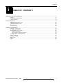
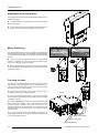
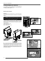
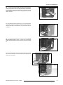
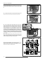
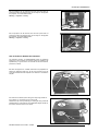
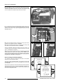
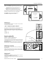
BARCO PROJECTION SYSTEMS RETRO DATA 2100LC R9001309 INSTALLATION MANUAL Date : 130298 Art. No : R5975968A Federal communication commission (FCC statement) This equipment has been tested and found to comply with the limits for a class B digital device, pursuant to Part 15 of the FCC Rules. These limits are designed to provide reasonable protection against harmful interference when the equipment is operated in a commercial environment. This equipment generates, uses, and can radiate radio frequency energy and, if not installed and used in accordance with the instruction manual, may cause harmful interference to radio communications. Operation of this equipment in a residential area is likely to cause harmful interference in which case the user will be required to correct the interference at his own expense. Instructions to the user : if this equipment does cause interference to radio or television reception, the user may try to correct the interference by one or more of the following measures : - Re-orientation of the receiving antenna for the radio or television. Relocate the equipment with respect to the receiver. Plug the equipment into a different outlet so that the equipment and receiver are on different branch circuits. Fasten cables connectors to the equipment by mounting screws. Note : The use of shielded cables is required to comply within the limits of Part15 of FCC rules and EN55022. Due to constant research, the information in this manual is subject to change without notice. Produced by BARCO NV, January 1998. All rights reserved. Trademarks are the rights of their respective owners. BARCO nv/Projection Systems Noordlaan 5 B-8520 Kuurne Belgium Tel : +32/56/368211 Fax : +32/56/351651 E-mail : [email protected] Visit Barco on the web : http://www.barco.com Printed in Belgium Contents i TABLE OF CONTENTS UNPACKING & PROJECTOR DIMENSIONS .................................................................................................................................................... 1 Unpacking .................................................................................................................................................................................... 1-1 Contents of the shipping boxes .................................................................................................................................................. 1-1 Projector dimensions ................................................................................................................................................................... 1-2 INSTALLATION SET UP ................................................................................................................................................................................... 2 Attachment of the projector Lens ............................................................................................................................................... 2-1 Cabinet Assembly ....................................................................................................................................................................... 2-1 Attachment of the Side Profile .................................................................................................................................................... 2-2 Mirror Positioning ......................................................................................................................................................................... 2-2 Focusing the Lens ...................................................................................................................................................................... 2-2 POWER UP CONSIDERATIONS ........................................................................................................................................................................ 3 Preparing your power cord ........................................................................................................................................................ 3-1 AC power cord connection ........................................................................................................................................................ 3-1 Enabling/Disabling the password ............................................................................................................................................... 3-2 Removing the projector ......................................................................................................................................................... 3-2 How to enable or disable the password ............................................................................................................................. 3-5 How to change the password menu ................................................................................................................................... 3-6 Switching on ............................................................................................................................................................................... 3-7 Projector status LED ................................................................................................................................................................... 3-7 Switching to standby .................................................................................................................................................................. 3-7 Switching off ............................................................................................................................................................................... 3-7 Lamp life ...................................................................................................................................................................................... 3-8 Fuses .......................................................................................................................................................................................... 3-8 5975968A RETRO DATA 2100LC 130298 i-1 Unpacking and Projector Dimensions 1 UNPACKING & PROJECTOR DIMENSIONS Unpacking Contents of the shipping boxes Dimensions Unpacking To open the banding around the carton, pull out the clip as shown: Take the lower projector cabinet and the upper mirror/screen cabinet out of its shipping carton and carefully place them on a solid level floor. Save the original shipping cartons and packing material, they will come in handy if you ever need to ship your retro projector. For maximum protection, repack your projector as it was originally packed at the factory. Contents of the shipping boxes : ¯ 1- Retro projector lower cabinet, containing one RBLD2100 projector, and one projector lens (the lens will be clamped inside the lower cabinet for shipping.) ¯ 1- Retro projector upper cabinet, comprising of one mirror/ screen cabinet, and two side profiles with fixing screws. And upper and lower cabinet attachment screws. ¯ 1- Power cord with outlet plug type ANSI 73.11. ¯ 1- Remote Control Unit, plus one 9V battery. ¯ 1- Owner's Manual ¯ 1- Installation Manual ¯ 1- Safety Manual 5975968A RETRO DATA 2100LC 130298 & & & 1-1 1-2 PROJECTOR RBLD2100 MOUNTING POSITION RBLD2100 MIRROR POSITION 1020mm 40.16" 1341.4mm 52.8" PROJECTOR WEIGHT : 144Kg PROJECTOR SCREEN SIZE : 67" 500mm 19.7" CENTRE OF GRAVITY 1371.4mm 54.0" 1005mm 39.6" 17mm 0.7" 1534mm 60.4" 500mm 19.7" 746mm 29.4" 1020mm 40.16" CENTRE OF GRAVITY 881mm 34.7" Unpacking and Projector Dimensions Projector dimensions (mm/") All measurements shown are in millimeters and inches. 5975968A RETRO DATA 2100LC 130298 1969mm 77.5" 941mm 37.0" 820mm 32.3" Installation Set Up 2 INSTALLATION SET UP Attachment of the projector Lens Cabinet Assembly Attachment of the Side Profile Mirror Positioning Focusing the Lens 352-(&7,21 +2/( 352-(&725 %$55(/ Attachment of the Projector Lens The projector lens is clamped during transportation inside the lower projector cabinet (lower left back side). Exercise care not to scratch or damage the lens when installing. To fix into position it is necessary to first unclamp the lens, by undoing the clamping screw completely. Lift carefully out by first pushing it slightly backwards (to clear the clamping hooks) and then pivoting up the farside of the lens and lifting out. Take the lens and place through the projection hole on top of the lower cabinet. The threaded end goes through first. Keep a tight hold of the lens and carefully lower, the lens and projector barrel will meet and the two will screw together. WARNING : ENSURE YOU HAVE REMOVED THE PROTECTIVE PACKING FOAM FROM INSIDE THE PROJECTOR BARREL FIRST. Screw onto the projector barrel in the clockwise direction ensuring good connection. The lens should screw in without resistance, if any resistance is felt (the two screw threads are not aligned) then untighten immediately and remove and try once more. Once proper connection is made, screw in the lens approximately three quarters of its length for focusing later. PROJECTOR LENS & CLAMPING HOOKS /(16 CLAMPING SCREW & PROJECTOR LENS PROJECTION HOLE Cabinet Assembly Attention : Avoid touching the screen while handling the screen cabinet in order to avoid any damage of the screen surface. Also exercise caution not to damage the projector lens when joining the cabinets together. Lift up the upper mirror cabinet and bring it down vertically onto the projector lower cabinet. &(17(5,1* 3,16 Both centering pins on the mirror cabinet must match and lock into the centering holes in the projector cabinet. Ensure also that the fixing holes in the upper mirror cabinet align with the holes in the lower projector cabinet. Once the cabinets are in place, two cabinet attachment screws are secured (in the fixing holes) from the rear side of the retro projector. The third is secured by reaching through the lower cabinet (rear side,) and securing through the far underside of the projection hole opening. This will require some care in manoeuvring as the fixing is recessed when the two cabinets are in place. Ensure each screw is tightened fully by hand. 5975968A RETRO DATA 2100LC 130298 RQXQGHUVLGH ),;,1* +2/(6 &(17(5,1* +2/(6 2-1 Installation Set Up Attachment of the side profiles The side profiles are packed during transportation inside the mirror cabinet (back side.) The side profiles are to be attached to the forward front sides of the upper cabinet. To fix in position turn in the screws a little and slide the profile over the screws, use the three screws provided for each profile. Mirror Positioning LOCKING SCREWS LOCKING SCREWS The Upper cabinet contains a mirror for reflecting and projecting the projector image onto the screen. During shipping or storage the mirror is pivoted into the upper cabinet, and locked by two hand tightable screws. To open up the mirror cabinet and locate into the operational position it is necessary to remove the two locking screws and pull out the mirror flap fully (as far as possible.) While holding the flap fully open, lock in position using the same locking nuts, but this time screw into the screw holes on the outer sides of the cabinet. 0,5525 23(5$7,1* 326,7,21) 0,5525 6+,33,1* 6725$*( 326,7,21) Focusing the Lens Focusing can only be achieved through access at the rear of the retro projector, while the projector is in its operational mode. A projector internal screen pattern may be used to assist focusing (see Service mode in owners manual.) Firstly ensure that the outer Front Rotary Lens Ring (a) is completely turned in the clockwise direction. Projector Loosen the Locking Fastener Ring (c) of the lens by turning counter clockwise a sufficient amount to allow turning of the Main Lens Barrel Tube (b). Focus the middle region of the screen by turning the Main Lens Barrel Tube in the clockwise or anti clockwise direction until the picture is focused. Attention: Do not turn out the lens to far, otherwise it will fall out of the lens holder. Once the barrel is in the desired position, lock the Fastener Ring (c) by turning clockwise until fully locked. It is now necessary to focus the corners of the picture by adjusting the Front Rotary Lens Ring (a), moving the desired amount in the anti clockwise direction. (a) Front Rotary Lens Ring (b) Main Lens Barrel Tube (c) Locking Fastener Ring 2-2 5975968A RETRO DATA 2100LC 130298 Power Up Considerations 3 POWER UP CONSIDERATIONS Preparing your power cord AC Power (mains) cord connection Enabling/Disabling the Password Switching On Projector Status LED Switching To Stand-By / Off Lamp Life Fuses Preparing your power cord Mains power cord with an ANSI 73.11 plug The wires of the delivered mains lead (power cord) are colored in accordance with the following code : Yellow and Green : ground (earth) White : neutral Black : live AC Power (mains) Cord Connection Warning ! Verify the power voltage corresponds to that of the wall outlet. Art. No. R9001309 must be connected to a 120V AC power source. The projector input voltage is adjusted to 120V AC on leaving the factory Use the delivered power cord to connect your projector to the wall outlet. Plug the female power connector into the male connector at the rear of the retro projector. The power voltage for the projector is indicated on the identification plate on the rear of the projector. ART No-R9001309 V -120V I -10Amp Freq -60Hz 9 POWER / MA Power cord connection This projector may be connected to an IT-power system. Ensure that the power switch is in the 'on-1' position on the rear control panel and also ensure the internal mains power plug is in place. The projector will not activate unless these two conditions are correctly undertaken. 2KP: / 5 72 /2 & $/&2 1 75 2/ 2 1 /< 3257 3257 5* %+&9 5*%+ &9 5 3257 9,'(2 5 3257 * * % % +& 9 $8',2287 / 5 9,'(2 3257 ,5 $8',2 ,1 & / 5 +& 6 9,'(2 9 $8',2 ,1 % / 5 $8',2,1$ /5 hard wire remote 56,1 56287 &2003257 &75/ Internal mains connection permanently connected Internal power switch always to be positioned in the ’1’ (ON) state 5975968A RETRO DATA 2100LC 130298 3-1 Power Up Considerations Enabling/Disabling the Password It is necessary to remove the projector from the lower cabinet to perform the changing of the pass word function. Follow the procedure for 'Removing the Projector' next. Removing the Projector Attention Follow the procedure as described below, it is recommended that a qualified Barco technician performs the alteration of the password function. WARNING : Power down all devices and switch off, disconnect all the input/output connectors to the projector. Unplug the power cord from the rear of the retro projector and lock the retro projectors rear positioning wheels. I It will be necessary to remove the front, rightside and leftside panelling, plus the associated strengthening supports of the lower projector cabinet, by either loosening or removing their fixing nuts. Tools Required Phillips screw driver (PH0) Flat Top Screw Driver Wrench, Spanner (No- 7,8,10) ',6&211(&7$//,1387287387 &211(&7256217+,63$1(/ û 2KP: /5 72/2&$/&21752/21/< 3257 3257 5*%+&9 5*%+&9 5 5 * * % % +& +& 9 9 3257 9,'(2 3257 9,'(2 Disconnect Power cord 3257 ,5 69,'(2 9 $8',2287 $8',2,1& $8',2,1% $8',2,1$ POWER / MA /5 /5 /5 /5 813/8*32:(562&.(7 35(66 WHEEL POSITION LOCK 'ON' WHEEL POSITION LOCK 'OFF' þ PRESS ê ý 352-(&7256/,'(5$,/ 21(,7+(56,'(2)352-(&725 6833257&52663/$7( 6833257&5266%$5 5,*+76,'(3$1(/ )5217&21752/3$1(/ )52173$1(/ FRONT CONTROL PANEL /()76,'(3$1(/ ,a. The front panel needs to be removed and this is achieved by firstly opening the front control panel and gaining access to the two large locking screws on either side of the control panel. Unlock by turning one half turn counter clockwise. The front panel can now be released from its mountings by tilting forwards slightly, then lifting upwards and outwards (the front control panel should remain in the open position at all times.) FRONT PANEL a FRONT PANEL LOCKING SCREWS 3-2 5975968A RETRO DATA 2100LC 130298 Power Up Considerations b. Once the front panel has been removed the internal projector and loud speakers are visible. The right loud speaker is of significance since, if it is chosen to remove the projector from the front direction, then this speaker must also be removed first. This is done by removing all four of its attachment nuts on the top and right pillars of the lower cabinet structure. b PROJECTOR The rightside panel must next be removed. The rightside panel is removed by loosening its attaching screws and then pivoting outwards the front edge of this panel a little, now pull the front edge out to release it. RIGHT SPEAKER RIGHTSIDE PANEL FIXING SCREWS î í a. Once the right panel has been removed the projector rightside bracket locking screw is visible. A mental note of this screws location should be made as it will be required to be undone in stage . a PROJECTOR RIGHTSIDE BRACKET LOCKING SCREW ,a. The leftside panel is removed by removing all its fixing screws both on the front and back. Once the screws are removed gently lever evenly out of its position. LEFTSIDE PANEL FRONT FIXING SCREWS a î LEFTSIDE PANEL BACK FIXING SCREWS 5975968A RETRO DATA 2100LC 130298 3-3 Power Up Considerations b. When the leftside panel is completely removed the projector leftside bracket locking screw is visible. Again a mental note of this screws position should be made as it requires undoing in stage b . LEFTSIDE BRACKET LOCKING SCREW The support cross bar at the rear and its attached support cross plate must also be removed by removing their fixing screws. SUPPORT BAR FIXING SCREWS SUPPORT PLATE FIXING SCREWS The two (rightside a & leftside b) bracket locking screws must be hand untightened to release the projector from its locked position. Once this is done the projector must be rotated on its attached brackets from its now operating position to the horizontal slide out position either in the clockwise (b) or counter clockwise directions, dependant on front or rear removal, remember it is still necessary to remove the right audio speaker if choosing to remove from the front side. Exercise caution during this procedure as the projector requires to be nudged slightly (just a couple of inches, but ensure the brackets are never in danger of leaving the slide rails) backwards or forwards to facilitate rotating and avoiding obstructions to the lens. The projector can now be pulled out and lifted clear of the cabinet. LOCKING NUT RIGHTSIDE BRACKET LOCKING SCREW a a The hand tightable projector bracket locking screws must be undone before the projector can be rotated to the horizontal exit position, it may be necessary to loosen the locking nuts slightly to facilitate untightening the bracket locking screws. RIGHTSIDE BRACKET LOCKING SCREW b 725(029()520)5217 b Access will be available to remove the projector either from the front or the back dependant on the direction of rotation. Note: Extra care must be observed not to damage or scratch the projector lens during the rotating process. A B C Ü 23(5$7,21$/ 326,7,21 OUT 5(029$/ 326,7,21 C B Û A 23(5$7,21$/ 326,7,21 OUT 5(029$/ 326,7,21 725(029()5205($5 3-4 5975968A RETRO DATA 2100LC 130298 Power Up Considerations The projector can be removed from the rear (rear slide out position) by pulling and gripping firmly until it is fully out. Gently place the projector on a solid stable surface. Warning: Projector is heavy. ê PROJECTOR REMOVAL POSITION FROM REAR The projector can be removed from the front (front slide out position) by pulling and gripping firmly until it is fully out. Gently place the projector on a solid stable surface. Warning: Projector is heavy. PROJECTOR REMOVAL POSITION FROM FRONT ê How to Enable or Disable the Password The password function is enabled/disabled when the password strap plug on the controller circuit board module is installed in the specified way. To get access to the controller circuit board module, proceed as follows; Place the projector on a stable solid surface in preparation for altering its password strap plug. All the fixing screws for the top cover are indicated and are required to be removed or loosened in step . Remove the leftside (when facing the lens) fixing bracket of the projector by unscrewing its two fixing bolts. Remove the top cover by loosening or undoing its fixing screws as indicated above. Then slide the cover backwards slightly and lift off, the internal structure will be now visible. PROJECTOR TOP COVER SCREWS PROJECTOR TOP COVER PROJECTOR FIXING BRACKET SCREWS 5975968A RETRO DATA 2100LC 130298 PROJECTOR TOP COVER PROJECTOR FIXING BRACKET 3-5 Power Up Considerations It is necessary to remove the metal cover plate behind which the password strap plug sits. To achieve this remove the four fixing screws and carefully lift clear the cover plate. The password strap on the controller circuit board module will now be visible. The strap plug can be seen approximately half way down on the left side of the circuit board. To change its position just unplug by pulling it out of its pins. The choice of password function is a user definable decision ! METAL COVER PLATE CONTROLLER CIRCUIT BOARD MODULE PASSWORD STRAP PLUG a. When the password strap is inserted into the right pin and the middle pin the password function is enabled. b. When the password strap plug is inserted into the left pin and the middle pin the password function is disabled. a b PASSWORD STRAP PLUG-ENABLE PASSWORD STRAP PLUG-DISABLE Once the password strap plug position has been chosen it is necessary to secure the projector. Follow the instructions in reverse order to reassemble the projector. Note : When rotating the projector back to its operational (in the lower cabinet) position you should hear a spring loaded 'click' as the projector bracket engages with the slide rail in the correct position. It will now be correctly positioned for the bracket locking screws to be tightened at both sides of the projector. How to Change the Password Menu It is required to enter into the Service mode (refer to the Owners manual for exact procedural steps.) First enter into the Adjustment Mode. Then press the control disc forwards or backward (on the RCU) to highlight Service and then press ENTER. Some items in the Service mode are password protected (when the password function is active.) Enter your password to continue. All other password protected items are now also freely available if you enter into the adjustment mode. ADJUSTMENT MODE Select a path from below : GUIDED RANDOM ACCESS INSTALLATION SERVICE Source 01 Select with or then <ENTER> <EXIT> to return. SERVICE IDENTIFICATION CHANGE PASSWORD CHANGE PROJ. ADDRESS CHANGE BAUDRATE PC RESET LAMP RUN TIME LAMP RUN TIME HISTORY PRESET INPUT BALANCE MORE ... Select with or then <ENTER> <EXIT> to return. 3-6 5975968A RETRO DATA 2100LC 130298 Power Up Considerations Highlight Change password by pressing the control disc up or down and then press ENTER to display the Change Password menu. SERVICE ENTER displays the Change Password menu EXIT returns to the adjustment selection menu. The old password is displayed and can be changed by entering the digit with the numeric keys of the RCU or local keypath. Press ENTER to save the new entered password. Press EXIT if no changes have to be made. IDENTIFICATION CHANGE PASSWORD CHANGE PROJ. ADDRESS CHANGE BAUDRATE PC RESET LAMP RUN TIME LAMP RUN TIME HISTORY PRESET INPUT BALANCE MORE ... Select with or then <ENTER> <EXIT> to return. CHANGE PASSWORD Enter new password 0000 Select with or then <ENTER> <EXIT> to return. Switching on Use the power switch to switch on the projector, using the switch on the front local control panel. REMOTE CONTROL PANEL When '0' is depressed, the projector is switched off. When '1' is depressed, the projector is switched on. The projector is switched ON and OFF using the power (mains) switch ON/OFF on the front local control panel keyboard To gain access to the keyboard, refer to 'Front local Control panel description and function' in chapter 1 'Location and function of control'. No light up : projector switched off Green color : projector in Operational mode Red color : projector is in Stand-by mode. To start image projection, press the 'Stand by' button on the front local control keypad or on the remote control. The projector mode status LED lamp will be green. When switching 'on' with the power switch, the projector starts in the stand by mode. The projector mode status LED lamp is red. EXIT ADDR ENTER STBY PAUSE MUTE HELP TEXT FREEZE B PHASE 1 Pressed : ON 0 Pressed : OFF Projector status LED ADJ + B + 9 0 7 8 5 6 3 4 + BRIGHTNESS 1 2 CONTRAST SHARPNESS B + TINT B + COLOR B Stand-By button Power Switch B + BASS + B + BALANCE TREBLE B B + B + VOLUME Projector Status LED Switching to stand-by When the projector is running and you want to go to stand-by, press the stand-by key. Caution : Before powering down the projector, switch the projector to stand-by and let the projector lamp cool down until the fans stop blowing (or for at least 15 minutes). FRONT CONTROL PANEL Switching off To switch off: - press firstly the STAND-BY key and allow projector to cool down until the fans stop blowing (or at least 15 min). - then switch off the projector with the power switch on the front local control panel. 5975968A RETRO DATA 2100LC 130298 3-7 Power Up Considerations Lamp life Lamp reference number description, No-R9829510 : 1000 hrs (standard lamp.) No-R9829600 : (optional long life reduced output wattage lamp.) 2000 hrs in normal mode (575w) and continuous operation. 3500 hrs in economic mode (400w) and continuous operation. 30 hours before the end of lamp lifetime, the following message will be displayed for 1 minute. This message will be repeated every 30 minutes. Press EXIT to remove the message before the minute is over. Lamp run time 980 h When the end of lamp lifetime is reached, the following message, with the exact run time is displayed on the screen. The total life time of the lamp for safe operation is 1000 hrs (NoR9829510) max. and 2000/3500hrs (No_R9829600) max. Operating the lamp longer than the lamps corresponding hours may damage the projector. Replace always with a same type of lamp. Call a BARCO authorized service technician for lamp replacement. M WARNING : Using a lamp for longer than its recommended lifetime is dangerous, the lamp could explode. :$51,1* /DPSUXQWLPHLVKRXUV 2SHUDWLQJWKHODPSORQJHU WKDQKRXUVPD\GDPDJH WKHSURMHFWRU 3OHDVHUHSODFHWKHODPS (17(5!WRFRQWLQXH Fuses Warning ! For continued protection against fire hazard : - replace with the same type of fuse. - refer replacement to qualified service personnel Fuse type : T16AH/250V 3-8 Order no. : B370076 5975968A RETRO DATA 2100LC 130298