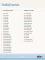
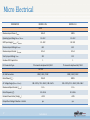
1
ABB - Power-One String Inverters 13-14.02.2014 Budapest, HU Attila Balogh, Jozef Krajcovic 0 Confidential Programme Company presentation Product overview and technical data Topology and functions Installation Commisioning and operation Communication and monitoring Correct sizing with Aurora Designer or Stringsizer 1 Power-One Company Presentation 40 years experience in power conversion #2 Global and fast growing supplier of PV inverters Manufacturing, Sales, Service and Design in Europe, North America and Asia Employees: 1900 (RE) – 3300 (Total) 2012 Revenue: $1.023 B Delivered inverters worldwide: more than 1 mill. units ≈ 11 GW, equal 5 nuclear power plants 2 Confidential Global Manufacturing Facilities Terranuova Bracciolini Toronto Phoenix Shenzhen 3 Confidential Manufacturing Plants Increased production capacity ITALY • Terranuova Bracciolini, Arezzo • Production capacity: 4GW 4GW US • Phoenix, Arizona • Production capacity: 1GW by the end of 2011 over 6GW CANADA • Toronto, Ontario • Production capacity: 0,5GW by the end of 2011 CHINA • Shenzhen • Production capacity: 1GW by the end of 2011 4 Confidential Power-One’s Installed Base – EMEA ~ 9GW Austria Germany Baltic Region Eastern Europe UK Balkan Turkey Benelux Israel France Arabic Iberian Peninsula Nordafrica Italy Switzerland 0-10MW 5 10-30MW Confidential Greece 30-300MW 300-500 MW <500 MW ABB and Power-One • Power-One has been acquired by ABB • ABB leading provider of power and automation technology with 145,000 employees in around 100 countries • Advantages of transaction - 6 Strong brand - increase the level of awareness Broadening of the PV inverter portfolio Increase customer satisfaction through global service infrastructure Expansion of its global presence for a quick entry into new markets Confidential Program Company presentation Product overview and technical data Topology and functions Installation Commisioning and operation Communication and monitoring Correct sizing with Aurora Designer or Stringsizer 7 Residential Renewable Energy / PV Product Offering New 0kW Commercial Utility 1kW PVI -10.0-I-OUTD PVI-12.0-I-OUTD PVI-400.0-TL/I PVI-275.0-TL/I 200 kW 300 kW PVI-330.0-TL/I PVI-220.0-TL/I 400 kW 2kW PVI-3.8-I-OUTD PVI-4.6-I-OUTD 4kW TRIO-27.6-TL TRIO-20.0-TL 5kW 30kW PVI-400.0-TL/I PVI-165.0-TL/I 40kW 50kW PVI-STATION-1320/1100-XX-DE PVI-STATION-770/1000-XX-DE PVI-STATION-700/440-XX-DE 500 kW PVI-6000-OUTD 6kW TRIO-5.8-TL TRIO-7.5-TL TRIO-8.5-TL 7kW 8kW 10 years PVI-12.5-OUTD-TL PVI-10.0-OUTD-TL PVI-8.0-OUTD-TL PVI-6.0-OUTD-TL 20kW PVI-3.0-OUTD PVI-3.6-OUTD PVI-4.2-OUTD 3kW 10 years 10 years 10kW 8 UNO-2.0-I-OUTD UNO-2.5-I-OUTD MICRO-0.25-I MICRO-0.3-I 600 kW 700 kW 100kW ULTRA 700.0 TL ULTRA 1050.0 TL ULTRA 1400.0 TL 800 kW Confidential PVI-330.0-TL/I PVI-110.0-TL/I 900 kW 150kW PVI-275.0-TL/I PVI-55.0-TL/I 200kW PVI-STATION-1320/1100-XX-IT PVI-STATION-770/1000-XX-IT PVI-STATION-700/440-XX-IT 1MW 1.5 MW PVI-220.0-TL/I 300kW 400 kW ULTRA-STATION-1500-IT ULTRA-STATION-2200-IT ULTRA-STATION-3000-IT 2.0 MW 2.5 MW 3MW Residential Renewable Energy / PV Product Offering MICRO-0.25-I MICRO-0.3-I New UNO-2.0-I-OUTD UNO-2.5-I-OUTD PVI-3.0-OUTD PVI-3.8-I-OUTD PVI-6000-OUTD PVI-3.6-OUTD PVI-4.6-I-OUTD PVI-4.2-OUTD TRIO-5.8-TL TRIO-7.5-TL TRIO-8.5-TL 0kW 9 1kW 2kW 3kW 4kW Confidential 5kW 6kW 7kW 8kW Renewable Energy / PV Product Offering Commercial 10 years 10 years 10 years PVI -10.0-I-OUTD PVI-12.0-I-OUTD PVI-12.5-OUTD-TL PVI-10.0-OUTD-TL PVI-8.0-OUTD-TL PVI-6.0-OUTD-TL TRIO-27.6-TL TRIO-20.0-TL PVI-400.0-TL/I PVI-165.0-TL/I 10kW 10 20kW 30kW 40kW 50kW Confidential PVI-330.0-TL/I PVI-110.0-TL/I 100kW 150kW PVI-275.0-TL/I PVI-55.0-TL/I 200kW PVI-220.0-TL/I 300kW 400 kW Renewable Energy / PV Product Offering PVI-400.0-TL/I PVI-330.0-TL/I PVI-275.0-TL/I PVI-220.0-TL/I Utility ULTRA 700.0 TL ULTRA 1050.0 TL ULTRA 1400.0 TL PVI-STATION-1320/1100-XX-DE PVI-STATION-770/1000-XX-DE PVI-STATION-700/440-XX-DE PVI-STATION-1320/1100-XX-IT PVI-STATION-770/1000-XX-IT PVI-STATION-700/440-XX-IT 200 kW 11 300 kW 400 kW 500 kW 600 kW 700 kW 800 kW Confidential 900 kW 1 MW 1.5 MW ULTRA-STATION-1500-IT ULTRA-STATION-2200-IT ULTRA-STATION-3000-IT 2.0 MW 2.5 MW 3 MW String / Central Inverter Monitoring – Aurora Logger Certified Inverters • • • • • • • • • • • • • • • • • • • • • • • • • • • • 13 • RWE / EDF minősített inverterek UNO-2.0-I-OUTD UNO-2.0-I-OUTD-S UNO-2.5-I-OUTD UNO-2.5-I-OUTD-S PVI-6.0-TL-OUTD PVI-6.0-TL-OUTD-S PVI-6.0-TL-OUTD-FS PVI-8.0-TL-OUTD PVI-8.0-TL-OUTD-S PVI-8.0-TL-OUTD-FS TRIO-5.8-TL-OUTD TRIO-7.5-TL-OUTD TRIO-8.5-TL-OUTD TRIO-20.0-TL-OUTD-400 TRIO-20.0-TL-OUTD-S2-400 TRIO-20.0-TL-OUTD-S2X-400 TRIO-20.0-TL-OUTD-S2F-400 TRIO-20.0-TL-OUTD-S1J-400 TRIO-20.0-TL-OUTD-S2J-400 TRIO-27.6-TL-OUTD-400 TRIO-27.6-TL-OUTD-S2-400 TRIO-27.6-TL-OUTD-S2X-400 TRIO-27.6-TL-OUTD-S2F-400 TRIO-27.6-TL-OUTD-S1J-400 TRIO-27.6-TL-OUTD-S2J-400 • • • • • • • • • • • • • • • • • • • • • Confidential E.ON Minősített inverterek listája Uno-2.0-I-OUTD 2 kVA 1F Uno-2.5-I-OUTD 2,5 kVA 1F PVI-3.0-TL-OUTD 3 kVA 1F PVI-3.6-TL-OUTD 3,6 kVA 1F PVI-4.2-TL-OUTD 4,2 kVA 1F PVI-5000-TL-OUTD 5 kVA 3F PVI-6000-TL-OUTD 6 kVA 3F PVI-6.0-TL-OUTD 6 kVA 3F PVI-8.0-TL-OUTD 8 kVA 3F PVI-10.0-TL-OUTD 10 kVA 3F PVI-10.0-I-OUTD 10 kVA 3F PVI-12.5-TL-OUTD 12,5 kVA 3F PVI-12.5-I-OUTD 12,5 kVA 3F Trio-5.8-TL-OUTD Trio-7.5-TL-OUTD Trio-8.5-TL-OUTD Trio-20.0-TL-OUTD 20 kVA 3F Trio-27.6-TL-OUTD 27,6 kVA 3F Technical details AURORA MICRO – module inverter AURORA UNO-2.0/2.5-I-OUTD - 1-phasestring-inverter Other 1-phase string-inverter PVI-6.0/8.0/10.0/12.5-TL-OUTD 3-phase-string-inverter TRIO - 5.8/7.5/8.5 kW-TL-OUTD 3-phase-string-inverter TRIO-27.6-TL-OUTD & TRIO-20.0-TL-OUTD 3-phase-string-inverter 14 Why Use MICRO? High energy harvesting • High efficiency • MPP tracking at module level High reliability • Natural convection cooling • Electrolyte free • No «single point of failure» Fast installation Easy to use Flexible PV plant planning 15 • No costly DC cabling • «Plug&Play» AC wiring • Quick design • Wireless communication • Integrated Web-Server (CDD) • Integration into the DSL home network • Wide input voltage range • Compatible with almost any type of PV module • Realization of small systems Confidential Micro Installation Advantages Installation flexibility Suitable for complex application (different orientation, tilt and azimuth) Maximum expansion Module indipendence and replacement flexibility 16 Confidential Micro Electrical PARAMETER MICRO-0.25-I MICRO-0.3-I INPUT Maximum Input Power Pdcmax 265 W 320 W Operating Input Range Vdcmin...Vdcmax 12...60 V 12...60 V MPP Input range VMPPmin...VMPPmax 25...50V 30...50V Maximum Input Voltage Vmax,abs 65 V 65 V Maximum Input Current Idcmax,abs 10.5 A 10.5 A Start Up Input Voltage Vstart 25 V 25 V Number of DC Inputs Pairs 1 1 PV connector Amphenol H4 / MC4 PV connector Amphenol H4 / MC4 DC Connection Type OUTPUT AC Grid Connection 208V / 240V / 230V 208V / 240V / 230V Rated Power (Pac,r) 250 W 300 W AC Voltage Range (Vacmin...Vacmax) 183...229 V / 211...264 V / 180...264 V 183...229 V / 211...264 V / 180...264 V Maximum Output Current (Iac,max) 1.3 A 1.5 A 50 - 60 Hz 50 - 60 Hz > 0.95 > 0.95 yes yes Rated Frequency (fr) Nominal Power Factor (Cosphiac,r) Output Over Voltage Protection - Varistor 17 Confidential AURORA MICRO Wireless communication gateway CDD web User-friendly free of charge web-portal data monitoring Highest efficiency in the market 96.5% CEC 18 Confidential Installation - Overview Waterproof sealing cap PV module Mounting rail Junction box Waterproof cap Unlock tool MICRO „Drop“ cable DC cable MICRO inverter 19 TRUNK cable Temporary cap Waterproof cap Confidential AURORA MICRO Communication Architecture Local Monitoring with AURORA Integrated Web Server Wifi or Ethernet Wifi or Ethernet LAN Access Point User Internet Connection Wireless Communication Energy Harvesting with AURORA MICRO 20 Data Collection with AURORA CDD Confidential Remote Monitoring with AURORA EASY VIEW / VISION Web Portals MICRO - AC Trunk Cable system Drop” Cable : P/N/GND External Ground screw IEC 62109-1 “Trunk” connection cable Lengths (1.05m ; 1.70m ; 2.05m) Bus terminal (NEMA 4X) 21 Waterproofed cap (NEMA4X) Confidential 10AWG Tool Technical details AURORA MICRO – module inverter AURORA UNO-2.0/2.5-I-OUTD - 1-phasestring-inverter Other 1-phase string-inverter PVI-6.0-TL-OUTD & PVI-8.0-TL-OUTD 3-phase-string-inverter TRIO - 5.8/7.5/8.5 kW-TL-OUTD 3-phase-string-inverter TRIO-27.6-TL-OUTD & TRIO-20.0-TL-OUTD 3-phase-string-inverter 22 Why Use UNO? High energy harvesting High reliability • High efficiency • Wide input voltage range • Fast and precise MPP tracking algorithm • Monolithic aluminium alloy die-casting chassis • Natural Convection Cooling • Electrolyte free (only bulk electrolytic capacitors) • IP65 environmental protection rating Fast installation • “T” mounting bracket • Lifting cover for an easy access to the connection area • Graphic display Flexible PV plant planning • HF-Transformer isolation: negative, positive or floating terminal grounding • Wide input voltage range • 2 kW and 2.5 kW models Easy to use 23 The best solution for residential application • User-friendly interface • Graphic display • Remote connection Confidential AURORA® PVI-2.0-I and 2.5-I 24 • Isolated inverters with HF-Transformer for use with all types of PV panels • Higher and flat efficiency curve for consistent performance across wide range of input voltage and output power • International version (optimized stocking) • New clearly arranged graphic display • IP 65 enclosure for unlimited outdoor application • Integrated DC switch (-S Version) • Precise and fast MPP tracking algorithm • RS 485 interface or radio module for connection with PVIDesktop Confidential AURORA UNO Single phase grid connected inverter 2kW for residential applications Graphic display easy-to-use interface Natural cooling w/o fan IP65 (NEMA4x) enclosure 25 Ease of installation: mounting and wiring Confidential Fast Installation Technical description: Die-casting chassis Easy to use Flexibility The cover moves up to enter the configuration (rotary switches for installation country selection and grounding option) and the connection area (AC side and communication) The “T” mounting bracket allows a very easy wall installation. 26 Confidential Technical description: Die-casting chassis Reliability High frequency isolation transformer and output chokes “pocket” optimal thermal exchange between components and ambient thanks to reduced thermal resistance electronic components work at lower temperature for a greater reliability and lifetime “Wings” area: active devices 27 Input chokes “pocket” Confidential die-casting technology allows to have only one gasket reduced risk of water penetration Technical description: Electrolyte-free technology - no fans and IP65 enclosure 28 Hohe Reliability Zuverlässigkeit No fans and no electrolytic capacitors except for bulk caps IP65 enclosure with rear heatsink Removing two of the main causes of failures turns into the best level of reliability for our products The rear heat sink allows to perform an easy maintenance from the front of the inverter Confidential Flexibility Available models UNO-2.0-I-OUTD-S UNO-2.5-I-OUTD-S HFtransformator UNO-2.0-I-OUTD UNO-2.5-I-OUTD Negative and positive Ground connection selectable on the field (NG by default) 29 Confidential Country code selection using rotary dip switches Application Note: configuration GRIDSTANDARD UNO inverters are Universal Standard and the Grid Standard can be selected during the installation using the rotary switches, according to the following table If required, the display language can be changed from the default. Options: English, German, French, Italian, Spanish, Czech, Dutch Falls gewünscht, kann die Displaysprache geändert werden. Zur Auswahl stehen: Englisch, Deutsch, Französisch, Italienisch, Spanisch, Tschechisch und Holländisch 30 Confidential 1 2 Grid Standard Display Language 0 0 Not assigned ENGLISH 0 1 VDE 0126 @230V GERMAN 0 5 ENEL @230V ITALIAN 0 6 SPAIN @230V SPANISH 0 7 UK G83@230V ENGLISH 0 9 IRELAND@230V ENGLISH 0 A AUSTRALIA @ 230V ENGLISH 0 B ISRAEL @ 230V ENGLISH 0 D FRANCE @230V FRENCH 0 E BENELUX @230V FRENCH 0 F GREECE @230V ENGLISH 1 0 PORTUGAL @230V ENGLISH 1 1 CORSICA @230V FRENCH 1 2 HUNGARY @230V ENGLISH 1 3 CHINA @ 230V ENGLISH 1 6 CHECA Republic @230 V ENGLISH 1 7 GERMANY- VDE AR-N-4105 @230V GERMAN 1 8 ENEL CEI-021 @ 230V ITALIAN AURORA® PVI-2.0-I and 2.5-I String inverters 2.0 and 2.5kW – Single phase with HF transformer PVI-2.0-I-OUTD PVI-2.5-OI-UTD Rated DC Power [kW] 2.1 2.6 Maximal recommended DC Power [kW] 2.3 2.9 Input parametrs (DC Side) Input voltage range [V] 0.7x VStart to 520 (300V rated) Full power MPP range [V] 200 - 470 Full asymm. Operation MPP range N/A N/A Max. Input Voltage [V] 520 Input Activation Voltagan VStart [V] 200 default (adjustable 120 - 350 via Display and Software) Number of independent MPP inputs 1 Maximal Input Power per MPPT [kW] 2.3 2.9 Number of DC Inputs( Connection pairs) 2 Maximal Input Current per MPPT [A] 31 200 - 470 10 (15 Short Circuit Current) 12.8 (15 Short Circuit Current) DC Varistor 2 DC Switch Integrated (600Vdc/16A) Confidential AURORA® PVI-2.0-I and 2.5-I String inverters 2.0 and 2.5kW – Single phase with HF transformer PVI-2.0-I-OUTD PVI-2.5--IOUTD Rated AC power [kW] 2.0 2.5 Maximal AC power [kW] 2.2* 2.75* Output (AC Side) Grid connection Single phase Rated AC voltage [V] 230 Maximal AC Voltage Range [V] 180-264 Maximal AC Current (Imax) [A] 10.0 12 Short Circuit Current 15.0 15.0 Rated Grid Fequency [Hz] 50 AC Varistor 2 P-N; P-PE Rated Power Factor cos(ϕ) 1 Total Current Harmonic Distortion (THD) <2% at Rated power and sinusoidal voltage Maximal Efficiency 96.3% Euro Efficiency (CEC) 95.0% Standby Cosumption < 8W Feed in Power Treshold [W] 24 Night Time Power loss [W] < 0.6W Isolation Yes (HF Trafo) * In Germany limited to 2.0kW resp. 2.5kW 32 Confidential Technical details AURORA MICRO – module inverter AURORA UNO-2.0/2.5-I-OUTD - 1-phasestringinverter Other 1-phase string-inverter PVI-6.0-TL-OUTD & PVI-8.0-TL-OUTD 3-phase-string-inverter TRIO - 5.8/7.5/8.5 kW-TL-OUTD 3-phase-string-inverter TRIO-27.6-TL-OUTD & TRIO-20.0-TL-OUTD 3-phase-string-inverter 33 Why use PVI-3.0/3.6/4.2-OUTD ? High energy harvesting High reliability Fast installation Easy to use Flexible PV plant planning 34 • High efficiency curve • Double independent MPPTs • Fast and precise MPP tracking algorithm • Natural convection cooling • IP65 environmental protection rating • Wide temperature range • Easy mounting system • Multi-country selection • Handy connection area • User-friendly display • RS485 interface as standard • Wide input voltage range • 3.0 / 3.6 and 4.2 KW models • Reactive power capability and 70% controllability Confidential AURORA® PVI-3.0/3.6/4.2-OUTD • • • • • • • • • • • 35 IP65 (NEMA 4) completely sealed unit box for use in harshest environmental conditions Extreme compact outdoor design: 4200W output power in box (547mm x 325mm x 208mm) and weight less than 17 kg Heat sink in front keeps inverter clean and the cooling remains very effective Tranformerless. Efficiency 96,8% 2 independent MPP Inputs Overload: PVI-4.2 works up to 4.6 kW under most conditions 2- lines LCD Display DC connectors - standard DC Multi-Contact MC4 Screw terminal block (3.0/3.6/4.2) or terminal clamp (PVI-6000) on AC side RS485 interface and USB service connection International version Confidential AURORA® PVI-3.0/3.6/4.2-TL-OUTD & PVI-5000/6000-OUTD String Inverters 3kW - 6kW – Single phase PVI-3.0-TL-OUTD PVI-3.6-TL-OUTD PVI-4.2-TL-OUTD PVI-5000-OUTD PVI-6000-OUTD Rated DC Power [kW] 3.12 3.75 4.38 5.15 6.18 Maximal recommended DC Power [kW] 3.5 4.15 4.82 5.3 6.4 Input parametrs (DC Side) Input voltage range [V] Full power MPP range [V] Full asymm. Operation MPP range 0.7x VStart to 580 (360 rated) 160-530 120-530 140-530 140-530 170-530 200-530 @2kW 190-530 @3kW 190-530 @3kW 220-530 @ 4kW 220-530 @ 4kW Max. Input Voltage [V] 600 Input Activation Voltagan VStart [V] 200 rated (adjustable 120-350 via Software and Display) Number of independent MPP inputs 2 2 2 2 2 Maximal Input Power per MPPT [kW] 2 3 3 4 4 2 (1 per MPPT) 2 (1 per MPPT) 3 (2 on MPPT 1 1 on MPPT 2) 10 (12.5) 16 (20) 16 (20) Number of DC Inputs( Connection pairs) Maximal Input Current per MPPT [A] 4 (2 per MPPT) DC Varistor 4 (2 per MPPT) DC Switch Integrated (600Vdc/25A) 36 Confidential 18 (22) 4 (2 per MPPT) 18 (22) AURORA® PVI-3.0/3.6/4.2-TL-OUTD & PVI-5000/6000-OUTD String inverters 3-6–6kW Single phase PVI-3.0-TL-OUTD PVI-3.6-TL-OUTD PVI-4.2-TL-OUTD PVI-5000-OUTD PVI-6000-OUTD 3 3.6 4.2 4.6 6.0 3.3* 3.96* 4.6* 5.0 6.0 Output (AC Side) Rated AC power [kW] Maximal AC power [kW] Grid connection single phase Rated AC voltage [V] 230 Maximal AC Voltage Range [V] Maximal AC Current (Imax) [A] Short Circuit Current 187.2-224.6 (208 Vr) / 216-259.2 (240 Vr) / 249.3-299.2 (277 Vr) 14,5 17,2 20 22 30 16 19 22 30 30 Rated Grid Fequency [Hz] 50 AC Varistor 2 ( Live - Neutral / Live - PE ) Rated Power Factor cos(ϕ) Total Current Harmonic Distortion (THD) Maximal Efficiency Euro Efficiency (CEC) 1 (adjustable ±0.9) <3.5% at Rated power and Sinusoidal voltage <2% 96.8% 97% 96% 96,5% Standby Cosumption 8 Feed in Power Treshold [W] 20 Night Time Power loss [W] <2 Isolation No (Transformerless) * In Germany limited to 3.0, 3.6 resp. 4.2 kW 37 Confidential Technical details AURORA MICRO – module inverter AURORA UNO-2.0/2.5-I-OUTD - 1-phasestring-inverter Other 1-phase string-inverter PVI-6.0/8.0/10.0/12.0-TL-OUTD 3-phase-string-inverter TRIO - 5.8/7.5/8.5 kW-TL-OUTD 3-phase-string-inverter TRIO-27.6-TL-OUTD & TRIO-20.0-TL-OUTD 3-phase-string-inverter 38 Why use PVI-6.0/8.0/10.0/12.0? High energy harvesting High reliability • Natural Convection Cooling • Electrolyte-free (no electrolytic capacitors) • IP65 environmental protection rating • Designed for 12.5kW power range Fast installation • Easy mounting system • Multi-country selection Flexible PV plant planning 39 • High efficiency • Wide input voltage range (up to 900V) • Double Independent MPPTs • Fast and precise MPP tracking algorithm • Wide input voltage range (up to 900V) • Available with DC switch and fuses Confidential The best solution for rooftop installations General overview PVI-6.0/8.0/10.0/12.0 -TL-OUTD Natural convection cooling (internal fans only for inside air mixing) Very light and compact design Electrolyte-free technology for the highest reliability Front heat sink with solar umbrella Double MPPT Wide input voltage range (max 900VDC) Flat efficiency curve Installer-friendly connection system Different configurations for the highest flexibility (single/double MPPT) 40 IP 65 chassis for outdoor installation Confidential Country code On-site selection (by display) PVI-6.0/8.0/10.0/12.5-TL-OUTD: easy to handle Fast Installation Installer-friendly wall mounted system The inverter’s wall connection system has been designed so that you’ll be able to install your own product just performing a few easy on-site actions. 41 Confidential AURORA® PVI-6.0/8.0/10.0/12.5-TL-OUTD • • • • • • • • 42 Designed for extreme long lifetime “Electrolyte free” 10 years Standard warranty Wide temperature range: Maximal power up to 55°C Maintenance-free IP65 box with natural convection cooling 2 independent MPPT input chanels Extreme wide input voltage range: 200-850V DC Easy configuration for use with any type of Module and technology High and flat efficiency curve: high performance in wide input voltage and output power range Confidential AURORA® PVI-6.0/8.0/10.0/12.5-TL-OUTD String Inverters PVI-6.0-TL-OUTD PVI-8.0-TL-OUTD PVI-10.0-OUTD PVI-12.5-OUTD Rated DC Power [kW] 6.2 8,25 10.4 13.0 Maximal recommended DC Power [kW] 6.8 9 11.4 14.3 PVI-6, 8, 10 and 12.5 kW Three phase Input parametrs (DC Side) Input voltage range [V] Full power MPP range [V] Full asymm. Operation MPP range 0.7x VStart - 850 (580 rated) 200 - 750 270 - 750 250 – 750 @ 4.2kW 320 – 750 @ 5.5kW Max. Input Voltage [V] 360-750 @ 6.5kW 360 - 750 445-750 @8kW 900 Input Activation Voltagan VStart [V] 360 default (Adjustable 250 - 500 via Display and Software) Number of independent MPP inputs 2 2 2 2 Maximal Input Power per MPPT [kW] 4.2 5.5 6.5 8.0 Number of DC Inputs ( Connection pairs) Maximal Input Current per MPPT [A] 2 (-S Version) 3 (Standard or -FS Version) for each MPPT 17 (22 Short circuit) DC Varistor 18 (22 Short circiuit) 4 (2 for each MPPT) DC Switch 43 300 - 750 Integrated (for S- and FS-versions) Confidential AURORA® PVI-6.0/8.0/10.0/12.5-TL-OUTD String inverters PVI-6.0-TLOUTD PVI-8.0-TL-OUTD PVI-10.0-OUTD PVI-12.5-OUTD Rated AC power [kW] 6.0 8.0 10.0 12.5 Maximal AC power [kW] 6.6* 8.9* 11.0* 13.8* PVI-6, 8, 10 and 12.5 kW Three phase Output (AC Side) Grid connection Three phase Rated AC voltage [V] 3x400 Maximal AC Voltage Range [V] 311-456 Maximal AC Current (Imax) [A] 10.0 13.0 16.6 20 Short Circuit Current 12.0 15.0 19.0 22 Rated Grid Fequency [Hz] 50 AC Varistor 3 ( 3 Starconection) Rated Power Factor cos(ϕ) 1 (adjustable±0.9) Total Current Harmonic Distortion <2% at Rated power and Sinusoidal voltage Maximal Efficiency 97.6 % 97.8% Euro Efficiency (CEC) 96.5 % 97.3% Standby Cosumption [W] < 10 Feed in Power Treshold [W] < 30 Night Time Power loss [W] <2 Isolation No (transformerless) * In Germany limited to 6.0, 8.0, 10.0, 12.5kW 44 Confidential Hockenheim: On a length of 405 meters, 4,716 solar panels were installed. This corresponds to a power of 848.88 kWp, which are fed with Aurora inverters into the grid. PVI-12.5 were used. 45 Confidential Technical details AURORA MICRO – module inverter AURORA UNO-2.0/2.5-I-OUTD - 1-phasestring-inverter Other 1-phase string-inverter PVI-6.0/8.0/10.0/12.5-TL-OUTD 3-phase-string-inverter TRIO - 5.8/7.5/8.5 kW-TL-OUTD 3-phase-string-inverter TRIO-27.6-TL-OUTD & TRIO-20.0-TL-OUTD 3-phase-string-inverter 46 Product overview 47 • Three-phase transformerless inverters • Designed for residential applications • Suitable for outdoor installation • Three different power ratings (5,800VA, 7,500VA and 8,500VA nominal power) Confidential Product overview TRIO-X.X-TL-OUTD Versions: Standard S: Standard version plus DC disconnect switch and MC4 type inputs TRIO-5.8-TL-OUTD-S TRIO-7.5\8.5-TL-OUTD-S 48 Confidential Features overview 49 • 2 independent MPPT channels for TRIO-7.5/8.5 and 1 MPPT channel for TRIO-5.8 • 2 DC input per MPP tracker, possibility to be configured in parallel • Universal standard grid connection • Reactive power management Confidential Characteristics overview • Sliding cover • Upgradeable firmware by the means of SD card. • Datalogger and smart grid functionalities on expansion slot “Service board” expansion card option Ethernet expansion card option (Modbus/TCP web server) 50 Confidential Characteristics overview Service Board • Power Management Unit (PMU) functionalities • External sensor inputs AN1 AN2 PT100/PT1000 • 51 Confidential Additional RS485 with MODBUS protocol Characteristics overview Ethernet board 52 Confidential • Remote control and monitoring with AURORA VISION • Integrated web server • Remote upgrading functionalities Tecnical description: other options 53 NEGATIVE GROUNDING KIT PVI-RADIOMODULE To be installed removing the front cover, for the ground connection of the DC negative input To be installed in the expansion slot, for the radio communication Confidential Technical description: block diagram 54 5 | Confidential Technical details AURORA MICRO – module inverter AURORA UNO-2.0/2.5-I-OUTD - 1-phasestring-inverter Other 1-phase string-inverter PVI-6.0/8.0/10.0/12.5-TL-OUTD 3-phase-string-inverter TRIO - 5.8/7.5/8.5 kW-TL-OUTD 3-phase-string-inverter TRIO-27.6-TL-OUTD & TRIO-20.0-TLOUTD 3-phase-string-inverter 55 The best solution for mid-large commercial PV applications. Why use TRIO? High energy harvesting High reliability Fast installation Easy to use Flexible PV plant planning 56 • High efficiency • Wide input voltage range (up to 1000V) • Double independent MPPTs • Fast and precise MPP tracking algorithm • Natural convection cooling • Electrolyte free (no electrolytic capacitors) • IP65 environmental protection rating • Detachable Wiring Box • Graphic display • Graphic display • Remote connection • Wide input voltage range (up to 1000V) • 4 different options for the wiring box • 20.0 and 27.6 kW models Confidential TRIO-20.0/27.6-TL-OUTD Intermediate product between string and central inverters High energy harvesting High reliability Flexible PV plant planning Performance: Maximal efficiency: 98,3% EURO Efficiency: 98,0%; Integrated MPPT Scanning Function. Reliability: Elektrolyt-free, natural convection cooling, full „fan-free“. Flexibility: Two independent MPPT (parallel) for maximal configuration flexibility up to 1000 Vdc input voltage. TRIO-20.0-TL-OUTD TRIO-27.6-TL-OUTD 57 Confidential AURORA TRIO 3-phase grid-connected string inverters from 5.8kW to 27.6kW 2-piece construction cost effective handling and installation 58 Confidential Stringcombiner available in multiple configurations including • MOV • DC Fuses • AC and DC disconnects • String current sensing AURORA® PVI-20.0/27.6-TL-OUTD Blockdiagrams 20.0/27.6kW vary in “S2X“ (4x2) per MPPT resp. (5x2) per MPPT 59 Confidential AURORA® PVI-20.0/27.6-TL-OUTD Ref. Description Ref. Description 09 Communication board 16 AC Cable gland 10 Service cable glands 17 AC output terminal block 14 AC- DC Switch 22 String fuses 15 DC overvoltage surge arresters Special versions S1J and S2J 60 Confidential Fast Installation Technical description: Flexibility Detachable wiring box (S2X Version) Input Class II overvoltage protections Fixing screw Communication board with RS485 I/F, memory expansion slot, SD card, slot for radio module Output Class II overvoltage protections AC connections DC+AC Switch Single string monitoring (current sensing and fuses status 61 DC (MC4 / WM) connectors: 27.6kW: 5 pairs/MPPT 20.0kW: 4 pairs/MPPT Confidential High reliability Technical description No electrolytic capacitors, no fans High reliability for our products 62 Confidential IP65 housing with rear heatsink The rear heat sink allows to perform easy maintenance from the front of the inverter Application Note: configuration GRID STANDARD TRIO inverters are Universal Standard and the Grid Standard can be selected during the installation using the rotary switches a05, according to the following table If required, the display language can be changed from the default. Options: English, German, French, Italian, Spanish, Czech, If required, the Display language can beDutch changed from the default choosing between one of the following: English, German, French, Italian, Spanish, Czech, Dutch 63 Confidential AURORA® PVI-20.0/27.6-TL-OUTD String Inverters 20.0 and 27.6kW – Three phase PVI-20.0-TL-OUTD PVI-27.6-TL-OUTD Rated DC Power [kW] 20.75 28.6 Maximal recommended DC Power [kW] 23.32 29.25 Input parametrs (DC Side) Input voltage range [V] 0.7x VStart - 970 (620 rated) Full power MPP range [V] 440-800 Full asymm. Operation MPP range 480-800 @ 6.5kW Max. Input Voltage [V] 500-800 @8kW 1000V Input Activation Voltagan VStart [V] 360 rated (adjustable 250 - 500 via Display and Software) Number of independent MPP inputs 2 2 Maximal Input Power per MPPT [kW] 12 16 8 (4 pro MPPT)1) 10 (5 pro MPPT) 1) 25 (30 Short circuit) 32 (40 Short circuit) Number of DC Inputs( Connection pairs) Maximal Input Current per MPPT [A] DC Varistor Varistors; S2X Version: Typ II Arrester DC Switch Integrated (1000Vdc/40A/MPP) 1) Only 64 500-800 S2F and S2X Version Confidential AURORA® PVI-20.0/27.6-TL-OUTD String inverters PVI-20.0 and PVI-27.6 – Three phase PVI-20.0-OUTD PVI-27.6-OUTD Rated AC power [kW] 20.0 27.6 Maximal AC power [kW] 22.0* 30.0* Output (AC Side) Grid connection Three phase Rated AC voltage [V] 3x400 Maximal AC Voltage Range [V] 320-480 Maximal AC Current (Imax) [A] 33.0 45.0 Short Circuit Current 34.0 46.0 Rated Grid Fequency [Hz] 50 AC Varistor Varistors; S2X Version: Typ II) Rated Power Factor cos(ϕ) 1 (adjustable ±0.9) Total Current Harmonic Distortion (THD) <2% at Rated power and Sinusoidal voltage Maximal Efficiency 98.2% Euro Efficiency (CEC) 98.0% Standby Cosumption < 8W Feed in Power Treshold [W] 40 Night Time Power loss [W] <2 Isolation No (transformerless) * In Germany limited to 20.0kW resp. 27.6kW 65 Confidential Harvesting Efficiency curve Efficiency curve TRIO-20.0-TL-OUTD TRIO-27.6-TL-OUTD 66 Confidential % Max. 98,3% EURO 98,0% CEC 98,1% In December 2012 one of the first solar parks in Bosnia and Herzegovina was connected with Power-One inverters to the electricity grid. The 150 kWp park „MK Hodovo 1“ is near Stolac, in the south of the country. 67 Confidential This 999 kWp roof installation in Londerzeel, Belgium, was completed in 2012 with Power-One's very reliable string inverters. 68 Confidential Program Company presentation Product overview and technical data Topology and functions Installation Commisioning and operation Communication and monitoring Correct sizing with Aurora Designer or Stringsizer 69 Energy conversion to alternating current Basic functions for a grid-connected inverter All inverters for grid-connected systems have at least the following core functions: Transformation / DC-AC Conversion To transform the direct current produced by the photovoltaic generator into alternate current and adapt it to the voltage level of the electrical grid for input into the grid. Automatic adjustment of the working point by MPPT algorithm To harvest the maximum available energy from solar radiation by adjusting the operating point on the power curve typical of the PV generator to make it work at the maximum power point MPP (Maximum Power Point). The maximum power point tracking function from the inverter through a special algorithm is called MPPT Protection and interface device for injecting electricity into the grid in compliance with current legal standards Function of monitoring the electrical parameters of the grid, to which one or more electromechanical relay switches are interlocked. These relays allow galvanic separation of the inverter from the grid according to the national legislation/norms. It is not mandatory that these functions are integrated with the inverter, nonetheless all manufacturers offer products which are including the above mentioned protections and interface device (especially for small inverters). Energy conversion to alternating current Transformation / DC-AC Conversion There are two types of static converters used in the field of photovoltaics: Grid-switching inverter Industrially-derived, they are based on the use of thyristors or GTOs and traditionally are used to pilot electric motors, including those in the traction sector. Although these are remarkably sturdy relatively cheap, they are no longer used in photovoltaic applications because they require large filter banks to suppress the current harmonics injected into the grid (fundamental square-wave current) and ensure compliance with EMC requirements. Switching Commutation Inverter Used in modern conversion systems based on sinusoidal PWM (Pulse Width Modulation), both for applications and photovoltaic converters. This inverter is based on “H” bridge architecture with IGBT (sometimes substituted by the half bridge in low power inverters). Operating at frequencies much higher than the grid frequency (6-20kHz), they allow a lighter weight and smaller size of the output reconstruction filter and obtain a low harmonic content of the current injected into the grid (THD<5%). Energy conversion to alternating current Automatic adjustment of the working point by means of an MPPT algorithm What is it used for? To maximize the energy harvested from the photovoltaic field, even in conditions of radiation variables How does it work? The inverter find the optimum working point in real time in such a way that the modules always operate in their maximum power point (Maximum Power Point Tracking). The static conversion system of energy Type of string inverter: dual stage insulated with high-frequency transformer conversion + DC / DC stage Galvanic. Isol. Filter EMI / EMC Inverter Relay interface network Filter EMI / EMC varistors AC network L Input DC _ Filter network N Varistors IGBT "H" bridge R-iso uP (supervisor) Inverter with "high-frequency" transformer The presence of the "push-pull" DC / DC stage with a high-frequency transformer allows for galvanic isolation with much more contained dimensions and weight than the conventional solution with a 50 Hz transformer. The stage of galvanic isolation provides a DC / DC conversion, therefore in order to continuously release components into the network this type of inverter must meet the same requirements and protections as transformerless inverters. High-frequency isolation is adopted mainly as a "step-up" function Energy conversion to alternating current Characteristics of inverters "isolated by a high-frequency transformer" Advantages and limitations of high frequency isolation technology Advantages: Downward extension of working input voltage range to be able to operate below the peak voltage of the grid (intrinsic limit of transformerless single stage of the technology). Ability to refer to ground one of the poles of the photovoltaic generator as required for some amorphous or crystalline silicon modules using "all-back contact” technology. Limitations: Efficiency generally lower than that of transformerless systems and centred on the lower limit of the input voltage interval. The DC/DC stage usually works only as a level translator and does not stabilize the working voltage of the inverter, which in turn is penalized when the input voltage increases. Voltage interval extended downward, but often limited on the upper end to around 500Vdc. In a trend opposite to the development of modern modules, modules often require numerous strings connected in parallel to limit the Vocmax. Energy conversion to alternating current String inverter topology: “"Transformerless with single-stage conversion"” + EMI/EMC Filter Inverter Grid filter Grid Interface Relay DC + AC GFCI EMI/EMC Filter varistors AC grid L DC Input N _ varistors "H" Bridge with IGBT IR uP (supervisor) Transformerless Single-Stage: Minimizing losses and higher conversion efficiency Lighter weight and more compact size compared to traditional inverters with 50Hz. isolation transformer High working frequency, beyond the audible range (> 18kHz), with the additional benefit of the miniaturization of filters. We are here to dispel a preconception. It is untrue that transformerless inverters are less safe than those having a transformer! Energy conversion to alternating current Characteristics of transformerless single-stage conversion inverters" The "pros" and some limitations of single-stage technology: Pros: High peak efficiency, combined with relative simplicity of the circuitry. Solution very effective if the input voltage range is rather small and particularly complex panels configurations are not required. Limitations: Range of input voltages limited and shifted "upward". The conversion and grid input is possible only for input voltages higher than the grid peak. Usually the DC range is between 350Vdc and 650/700Vdc for these inverters. High efficiency performance peaks, but only available in a narrow voltage range and in some cases "marginal" with respect to voltage variations inflicted on the PV generator by the heating of the cells and changes in radiation. The static conversion system of energy Multi-string inverter type: dual-stage transformerless conversion Transformerless with "dual-stage" type: Two steps of conversion at high frequency in cascade. The first stage is of DC / DC type, and it is usually given the task of stabilizing the voltage and reaching the maximum power point tracking (MPPT), while the second stage performs the DC / AC conversion to feed power into the grid (usually in an IGBT Hbridge) This is the structure used to create the multi-string inverter, by putting the output of 2 DC / DC converters in parallel with the H-bridge input it is possible to create 2 independent channels of maximum power point tracking. Energy conversion to alternating current Characteristics of “transformerless dual-stage conversion" inverters Advantages and limitations of "dual-stage" transformerless architecture Advantages: Input voltage range extremely wide Very flat efficiency curves, with performance rather insensitive to operating conditions and input voltage/output current. The inverter always operates at the optimal voltage level to maximize efficiency allowed by the stabilizing action of the DC/DC input converters. It is possible to create multiple independent input channels with different installation characteristics (orientation, tild or diferent panels) without compromising the energy output of the system. Better yield with multiple MPPT Note: Though the cost per kWp of these inverters is theoretically higher than that of single-stage systems, the higher energy output achieved makes it possible to recover any increased costs in a few years! Topology 1-Phase string inverters Transformerless Technology Minimizing losses and increasing conversion efficiency. Other adventages of “Dual Stage” topology: M • The inverter always operates in maximal efficiency region • Extrem wide input voltage range combined with flat efficiency curve Array can be split in 2 independent subarrays each with stand-alone maximum power point tracking. DC ELECTRICAL PANEL EXTERNAL DISCONNECT BOX INVERTER S1 F1 + DC IN 1 - F2 _+ SS2 EMI FILTER • RES ELECTR Booster1 kWh AC OUT Booster 2 DC IN 2 Riso Continuous Equipment Ground 79 Confidential GAS ARRESTOR DC+AC GFCI S2 Topology 3-Phase string inverters • True 3-phase bridge topology for DC/AC output converter (not 3 x single-phase inverters in one package!!) • Each MPPT input includes standard MultiContact® MC4 connection for 3 strings • Available with optional integrated DC switch and fused inputs, to complete the DC protection system for large plants without extra-costs or external components 12A max. per connection pair! Allowed increase up to 20A . 80 Confidential AURORA® PVI-3.0/3.6/4.2-TL-OUTD & PVI-5000/6000-OUTD String Inverters 3kW - 6kW – Single phase PVI-3.0-TL-OUTD PVI-3.6-TL-OUTD PVI-4.2-TL-OUTD PVI-5000-OUTD PVI-6000-OUTD Rated DC Power [kW] 3.12 3.75 4.38 5.15 6.18 Maximal recommended DC Power [kW] 3.5 4.15 4.82 5.3 6.4 Input parametrs (DC Side) Input voltage range [V] Full power MPP range [V] Full asymm. Operation MPP range 0.7x VStart to 580 (360 rated) 160-530 120-530 140-530 140-530 170-530 200-530 @2kW 190-530 @3kW 190-530 @3kW 220-530 @ 4kW 220-530 @ 4kW Max. Input Voltage [V] 600 Input Activation Voltagan VStart [V] 200 rated (adjustable 120-350 via Software and Display) Number of independent MPP inputs 2 2 2 2 2 Maximal Input Power per MPPT [kW] 2 3 3 4 4 2 (1 per MPPT) 2 (1 per MPPT) 3 (2 on MPPT 1 1 on MPPT 2) 10 (12.5) 16 (20) 16 (20) Number of DC Inputs( Connection pairs) Maximal Input Current per MPPT [A] 4 (2 per MPPT) DC Varistor 4 (2 per MPPT) DC Switch Integrated (600Vdc/25A) 81 Confidential 18 (22) 4 (2 per MPPT) 18 (22) Input activation voltage-Start voltage Vstart: Default: •200V for Single phase inverters Adjustable: 120V-350V •360V for Three phase inverters Adjstable: 250V-500V Status Grid connected Disconnection: at 70% VStart disconnected Vin [V] 0 90 100 140 200 120 Easy 300 400 500 adjustable via Display!! 600 • Input activation voltage “Vstart” is the input voltage when the grid connection starts!. • Vstart can be adjusted independent for each MPP-input (Vstart1 & Vstart2) • After start sequence the inverter stays grid connected till the grid voltge went down under 70% of Vstart • Maximal Flexibility in fitting of PV-Array disposition -> Reduction of undesirable grid connection and disconnections. 82 Confidential Power Derating vs Input voltage Power derating as a function of input voltage - Full Power MPPT Range PVI-4.2-OUTD Output power vs Input voltage Pout [W] 4500 4200 4000 3500 3000 2880 2500 Full Power MPPT range 2000 1500 1000 500 Vin [V] 0 90 100 140 200 300 400 500 530 600 580 Power derating at lower input voltage caused by limited current Linear power derating over 530Vdc (full power limit) to 580Vdc (disconnect) to avoid excessive overloading of Power transistors (IGBT) 83 Example shows the inverter with symmetrical load Confidential The problem of shading 84 Confidential The problem of shading 85 Confidential The problem of shading 86 Confidential MPP-Scan Function • Periodic “MPPT scan” function , to intercept and track the “absolute maximum” of the power curve among pultiple “relative maximum” points, under partial shading conditions of the PV array. “Absolute” Maximum “Relative” Maximal power points 87 Confidential AURORA® PVI-3.0/3.6/4.2-TL-OUTD & PVI-5000/6000-OUTD String inverters 3-6–6kW Single phase PVI-3.0-TL-OUTD PVI-3.6-TL-OUTD PVI-4.2-TL-OUTD PVI-5000-OUTD PVI-6000-OUTD 3 3.6 4.2 4.6 6.0 3.3* 3.96* 4.6* 5.0 6.0 Output (AC Side) Rated AC power [kW] Maximal AC power [kW] Grid connection single phase Rated AC voltage [V] 230 Maximal AC Voltage Range [V] Maximal AC Current (Imax) [A] Short Circuit Current 187.2-224.6 (208 Vr) / 216-259.2 (240 Vr) / 249.3-299.2 (277 Vr) 14,5 17,2 20 22 30 16 19 22 30 30 Rated Grid Fequency [Hz] 50 AC Varistor 2 ( Live - Neutral / Live - PE ) Rated Power Factor cos(ϕ) Total Current Harmonic Distortion (THD) Maximal Efficiency Euro Efficiency (CEC) 1 (adjustable ±0.9) <3.5% at Rated power and Sinusoidal voltage <2% 96.8% 97% 96% 96,5% Standby Cosumption 8 Feed in Power Treshold [W] 20 Night Time Power loss [W] <2 Isolation No (Transformerless) * In Germany limited to 3.0, 3.6 resp. 4.2 kW 88 Confidential Stand-by operation •Input voltage dropped under minimal input voltage (70% Vstart): Inverter stays a definded time connected to grid: UV-Protection time. During this time inverter consumes energy from grid!! (Standby consumption according to datasheet : <20W) • UV-Protection time is adjustable 1s - 3600s Advantages: • Inverter doesn’t need undergo hindering activation procedure • Higher profit eventhough short time Energy consumption from grid 89 Confidential Program Company presentation Product overview and technical data Topology and functions Installation Commisioning and operation Communication and monitoring Correct sizing with Aurora Designer or Stringsizer 90 Installation 150 mm (6”) Adhere distances (see the manual) -Side: USB and programming interfaces - Top: heat dissipation - Below: Access to the connectors - All sides: Mutual heating from multiple inverters 150mm 50 mm (2”) 200 mm (8”) • No expose to direct sunlight • Heat dissipation does not affect! Not on inclined surfaces mount (derating from 5 degrees inclination) 91 Confidential ( 6”) Installation (1) Adhere distances (see the manual) -Side: USB and programming interfaces - Top: heat dissipation - Below: Access to the connectors - All sides: Mutual heating from multiple inverters NO Do not mount on inclined surfaces (derating from 5 degrees inclination) 92 OK Confidential NO NO Installation (2) • Do not expose to direct sunlight! Do not interfere heat dissipation! NO 93 OK Confidential OK Installation GOOD! POSITION: Well ventilated protection: From direct sunlight by PV panels or metal frame Accessibility: Sideways (3.6 kW) BAD! Accessibility: No access from the side! 94 Confidential Installation GOOD! Thermal: Protected from direct sunlight No thermal mutual influence? Inverter BAD! Accessibility No access from the side! No accessibility ! GOOD! 95 Confidential Installation BAD! THERMAL LAYOUT The heat produced by the lower inverter increases the ambient temperature of the upper inverter! recommendation: Inverter can not order directly over each other! BAD 96 Confidential GOOD Installation and Configuration Accessories Complete installation kit: Multi Contact connectors Cable Glands (AC / communication) Jumpers prepared for the input configuration Tool (Torx and bent screwdriver) Mounting plate CD with communication software Operating and Installation Manual 97 Confidential DC Connection + Pol - Pol MPPT1 MPPT2 DC Switch + PV Input 1.1 + PV Input 1.2 - PV Input 1.1 MPPT 1 - PV Input 1.2 ≈ + PV Input 2.1 + PV Input 2.2 MPPT 2 AC Output DC/AC Inverter - PV Input 2.1 - PV Input 2.2 PVI-6000-OUTD PVI-6000-OUTD-S „Connection box" integrated in the inverter! 98 Confidential Independent or parallel operation? Selection of Input configuration – dual or single MPPT ?? Aurora Inverter MPPT1 PV1 + PV2 MPPT2 Grid + _ _ DUAL MPPT Mpp1 Aurora + Inverter + _ PV MPPT1 = MPPT2 Grid _ SINGLE MPPT Parallel connection is very easy ( no PC necessary); set up available from front side 99 Confidential Mpp2 Independent or parallel operation? Parallel connection is very easy ( no PC necessary); set up available from front side) Dual MPPT : • Panels with different orientation or partial shading • Uneven number of panels and even number of strings • Different type of panels Single (parallel) MPPT: • One string or array exceeds current/power of one input • Uniform array due to cost saving reasons only one cable can be laid 100 Confidential DC Connection Jumpers in parallel operation Miniature switches for MPP mode (status is after a restart activated!) Jumper (from unused input avoid incorrect measurements at the open input) 101 Confidential AC and Communication AC Connection: Screwed or clamped Observe Nationale regulations!! 102 RS 485 Communication: TR+, TR- and Gnd Connector is supplied Confidential Remote Input and alarm output Alarm: The NC (n.c) a normally open (n.o). Rating: 2A 230VAC max! The alarm contact has 2 functions adjustable via display! - Production: contact closes when inverter connected to the grid. Fault: contact closes by an error or if the inverter disconnects from the grid, but not at low voltage at the input (little light) „Remote Control“: Short circuiting contacts: Inverter shutdown! CAUTION: Do not feed external voltage! 103 Confidential Program Company presentation Product overview and technical data Topology and functions Installation Commisioning and operation Communication and monitoring Correct sizing with Aurora Designer or Stringsizer 104 Before starting up • Check Open circuit voltage at the input! • Check Input Polarity ! • Measure PV Field Insulation resistance (if possible) • Check phase sequence of 3-phase devices and phase-neutral of single phase devices • Check MPP mode • Make regional settings (For models with rotary switch) 105 Confidential Country- and language settings(1) TRIO-20.0/27.6 settings Switch left 106 Switch right Grid code Language 0 1 VDE-126-1-1 German 0 C BDEW German 1 7 VDE-AR-N 4105 German Confidential Country and language settings with rotary switch a05. Further adjustments according to manual Country- and language settings (2) UNO-2.0/2.5-I settings Switch 1 Switch 2 Grid code Language 0 1 VDE-126-1-1 German 1 7 VDE-AR-N 4105 German Country and language settings with rotary switch a09. Further adjustments according to manual Note: For some devices, the country must be set AFTER the startup via the display:? UNO-3.0/3.6/4.2 107 Confidential Start up sequence • Step 1: DC Switch turn on • Step 2: AC connecting Inverter behavior: •Case 1: DC voltage between 100V (200V) and VStart up; Input power> ca. 8W -> Inverter starts up display: waiting for Sun… -> Green LED „Power“ flashes“ • Case 2: DC voltage > Start up voltage (200V/360V default) -> Inverter starts checking of grid parameters (Voltage, Frequency) and measures the Insulation resistance Riso. Green LED flashes -> Inverter performs the internal self-test -> This process takes about 30 ... 60 seconds. The measured values are displayed on the screen. The green LED flashes. -> If are all parameters in order the inverter connects to the power and feeds Energy to the grid. The green LED is lit. Accumulated energy and other values are displayed After startup: Set time and date! Countries setting check In case of more inverters monitoring, set individual address for each one inverter. 108 Confidential Menu structure: Main Menu Graphic display : 2-line display : Built in: - UNO-2.0/2.5-I - TRIO-20.0/27.6 Built in: - UNO-3.0/3.6/4.2 - PVI-10.0/12.5-(I) The menu structure in the graphical display corresponds to the 2-line display 109 Confidential Menu structure: Main Menu Type and part number Type OUTD PN------------ Serial number and Firmware Version S/N--------- xxxxxx FW rel. C.0.1.1 Daily energy and daily income E-tod $-tod Total energy and total income E-tot ------------E-par 0 KWh EUR Output power, Inv. temperature P-out 0 W T-inv - °C Peak power overall, Today Ppk W Ppk Day ………...W Grid voltage current, average Vgrid 197 V Vgrid Avg 0 V Grid current, frequency Igrid Fgrid Input voltage, - Current 1 Vin1 I in1 0V 0.0 A Input voltage, - Current 2 Vin2 I in2 0V 0.0 A Input power 1 and 2 Pin 1 Pin 2 0W 0W Measured Riso and actual leakage current Riso Ileak Status and Date Inverter OK Wed 17 May 11 23 „Autorotate“ 110 Enter-button Confidential Blocked at a value 0 Wh 0.0 EUR 0.8 A 50.18 Hz 0.0 Mohm 73 mA Menu structure: Submenus Pressing the "ESC" button in the main menu takes you to the sub-menus Statistics Settings Info Password 0000 Lifetime Partial Today Last 7 days Last Month Last 30 Days Last 365 Days User period Address Display Set Service New Password Cash Time Language Vstart Autotest Alarm Remote Control UV Prot.time MPPT scan EN/DIS Scan Period Alarm Message Part number S-Number. Prod. week Firmware Note: Resetting of Partialcounters: Enter button press for more than 3 seconds! 111 Confidential Menu structure: submenu settings(1) Passwort: 0000 • Address: RS485 address setting • Display: Contrast, Backlight, Buzzer • Service: Only for Power-One • New Password • Cash: Sets the sum / KWh • Time: clock setting • Language: English and local language • VStart: startup voltage setting • Alarm: Set the alarm function (Production or Fault) • Remote control: Remote control, • UV Prot.time: connection time at input voltage fall bellow the minimum Input voltage. -> Standby mode! • MPP-scan EN/DIS -> not implemented on all models! • Scan Period: Time interval of MPP scans • Alarm Message: create your own alarm • Active power limitation (not the PVI-10.0/12.5) • Reactive power settings (not the PVI-10.0/12.5) 112 Confidential Menu structure: submenu settings Additional settings * • Reactive power No adjustment cos(phi) fix tan(phi) fix cos(phi) ) f(p) Q=f(U) • Power limitation Enter value • Analog inputs ( TRIO-20.0/27.6) Gain (Slope of the curve) Offset Unit PT 100 PT 1000 * Not all settings are available on all devices! 113 Confidential Meaninig of 3 LEDs Status of LED Function Green: Yellow: Red: Night mode Green: F Yellow: Red: Start up mode Green: Yellow: Red: Normall operation Green: Yellow: Red: 114 x x Isolations failure Green: Yellow: Red: Warning / Failure Green: F Yellow: Red: Failure: Missing Grid Confidential Description Fault – what now? • Fault is indicated: Yellow LED lights •The parameters which constantly triggered the fault check again • The fault disappears, the inverter goes back to the network -> Temporary disruption • Inverter did not connect to the grid? -> Hotline (Monday to Friday 8:00 to 17:00) • Stand by: type, serial number and exact description? (Error code, frequency of error) • Replacement unit will be delivered 115 Confidential Error Messages (1) CODE Possible cause Action Input Overcurrent Inpuy current-Sensor defective Boost MOSFET defective Wrong Stringconfiguration Check string configuration otherwise: Inverter Swap E002 Input Overvoltage 59oV Overvoltage surge protection Wrong String wiring Module/ String number zu high Wiring verification PV configuration verification E003 No parameters Wrong communication between DSPs Inverter Swap E001 Wrong String wiring Module/ String number zu high E004 Bulk Overvoltage E005 Communication Error No communikation between Micro and DSP Inverter Swap Output Overcurrent If error occurs randomly: Rapid change in grid voltage. -> inverter goes back on line Permanent error: Problems with the current measurement The network parameters verification otherwise Inverter swap IGBT Sat Overcurrent in the bridge: If error occurs randomly: change of the grid voltage, leakage current problem? Permanent error: HW error Check the DC insulation. If E007 is displayed before the grid connection could the cause be a leakage current. Otherwise: exchange E006 E007 116 Displayed description Confidential Wiring /PV configuration verification Error Messages (2) CODE 117 Displayed description Possible cause Action E008 Bulk undervoltage Wrong PV wiring HW Problem in Booster circuit String configuration and radiation verification Otherwise: Inverter swap E011 Ramp Fail Hardware Problem Inverter swap E012 DC-DC Error Hardware Problem Inverter swap E013 Wrong Mode Input configuration wrong set up: Schalter steht auf parallel: Strings sind aber nicht parallel: NEUSTART erforderlich! MPP Mode correct set up E014 Overtemperature Internes Problem oder extrem hohe Umgebungstemperature Mountinh verification: Otherwise exchange E015 Bulk Capacitor Fail Hardware Problem Inverter swap E016 Inverter Fail Internal Problem in DC-AC Stage Inverter swap E017 Start Timeout Probleme with DSP Software Inverter swap E018 Ileak Failure Leakage current to high or measurement failure Insulation of AC and DC Side check. Moisture can Increase the leakage current Otherwise: exchange E019 Ileak Sensor fail Leakage current measurement failure Inverter swap Confidential Error Messages (3) CODE Possible cause Action E020 DC-DC Relais Fail Input relay failure Inverter swap E021 Inverter Relais fail Output relay failure Inverter swap E022 Autotest timeout Internal failure Inverter swap E023 DC Injection Error DC voltage Sensor failure Inverter swap E024 Unknown Error Unknown internal failure Inverter swap E025 Riso low PV Field insulation failure (Insulation-resistance < 1 Mohm) Insolation resistance of Module verifcation or externe Overvoltage surge arresters check E026 VRef Error Internal reference out of limit Inverter swap VGrid measure Fault Redundant grid voltage meaurement out of limit FGrid Measure Fault Redundant grid frquency meaurement out of limit E027 E028 118 Displayed description Confidential Grid voltage verification Otherwise: Inverter swap Check country settings of inverter (IT for Italy, DE for Germany, etc.) , check frequency: Otherwise Inverter Swap Error Messages (4) CODE 119 Displayed description Possible cause E029 Zgrid Measure Failure Redundant impedance measurement out of limit Country set up verification Otherwise : Inverter Swap E030 Ileak Measure Fault Redundant Leakge current measurement out of limit Inverter swap E031 Wrong V Measure Redundant internal reference voltage measurement out of limit Inverter swap E032 Wrong I Measure Redundante internal reference current measurement out of limit Inverter swap E033 Undertemperature Tempere measurement failure Inverter swap E034 Interlock fail Internal failure Inverter swap E036 VOut Avg Average grid voltage is out of limit Grid voltage and set up verification Ansonsten: Otherwise inverter swap E037 Isolationsproblem (nur im Amorph Mode möglich) Pole grounding is no longer guaranteed Pole grunding verification E038 Mid Bulk OV Unbalanced voltage distribution of the bulk capacitors Inverter swap Confidential Action Warnings (1) CODE 120 Displayed description Possible cause Action W001 Sun low Insufficient radiation. Number of modules / string too small. Incorect wiring W002 Input undervoltage Input voltage to low As W001 W003 Grid Fail W004 Grid Overvoltage W005 Grid Undervoltage W006 Grid Overfrequency W007 Grid Underfrequency W008 Z Grid out of Range Grid impedance out of limit Wiring and gridimpedance parametrs verification W010 Fan Fail Fan failure Check if the fan is blocked because dirt, failure may cause derrating -> replace W011 Bulk undervoltage Input voltage to low Configuration verification W012 Clock Battery low Low battery (device stays on the grid) Battery replace W013 Clock Failure Problem with the time (unit remains on the grid) Set time. If the problem shows up again -> Swap inverter No action… waiting for Sun Configuration and wiring verification No action… waiting for Sun Configuration and wiring verification Grid voltage out of limit Grid voltage, frequency, inverter settings and AC wiring verificaion Grid frquency out of limit Confidential Warnings (2) CODE Displayed description Possible cause Action W017 Jbox Fail Fuses in connection box failed Fusses replace W018 SPD DC open Overvoltage surge arrester on DC Seide interrupted Surge arrester replace W019 SPD AC open Overvoltage surge arrester on AC Seide interrupted Surge arrester replace Note: Not all error messages and warnings are available on all devices 121 Confidential Software Aurora Manager-LITE (1) Used with the TRIO-20.0/27.6 and UNO-2.0/2.5-I devices Active power set up Reactive power set up Detailed information is available in the description of the software 122 Confidential Software Aurora Manager-LITE (2) Software «Aurora Manager-LITE Set up of AC Parameter Detailed information is available in the description of the software 123 Confidential Settings using software tools Used with the PVI-10.0/12-5 and PVI-3.0/3.6/4.2-TL devices Detailed information is available in the description of the software 124 Confidential Program Company presentation Product overview and technical data Topology and functions Installation Commisioning and operation Communication and monitoring Correct sizing with Aurora Designer or Stringsizer 125 Communication: RS485 RS485 signals are floating and each signal is transmitted over a + line and a - line. RS485 receiver compares the voltage difference between both lines, instead of the absolute voltage level on a signal line. With RS485 there is no any common zero as a signal reference. Several volts difference in the ground level of the RS485 transmitter and receiver does not cause any problems. 126 Confidential Communication: wiring PC with RS232 port 2nd Aurora Last Aurora 1st (Sub-D 9 pin male) Aurora (Sub-D 9 pin female) -T/R RTN +T/R PVI-RS232/485 RS485 to RS232 Converter S2 switch OFF -T/R (terminal block) RTN RS-485 cable max. length = 1.000mt max. inverter nodes = 31 +T/R -T/R RTN S2 switch OFF +T/R -T/R RTN Off +T/R -T/R RTN +T/R (terminal block) S2 switch ON Data-Logger RS485 port On Cable: Data cable, twisted Recommended RS-485 cablepair type:and shielded: LiYCY, 2x2x0,5mm (n.2 twisted pairs) + shield Minimum cross section: 0.5mm2 RS-485 cable (1pair + 1 conductor) + shield Block Diagram: RS-485 cabling AURORA PVI-6000-OUTD NOTE: Each inverter requires its own address! 127 Confidential Cables for RS485 applications Example: BELDEN 128 Confidential Cables for RS485 applications Example: CEAM 129 Confidential Monitoring - Power-One offer Local monitoring PVI-USB-RS485_232 (USB / RS-485&RS-232 converter) PVI-RADIOMODULE (wireless communication board) AURORA COMMUNICATOR (Local monitoring sw platform) PVI-DESKTOP (Remote display) Remote monitoring PVI-CDD (data logger for AURORA MICRO) PVI-AEC-EVO (EVO data logger ) AURORA VISION (Advanced web portal) VSN-MGR-RES-P1 (AURORA LOGGER data logger ) AURORA EASYVIEW (Residential web portal) AURORA Communicator - local monitoring CommunicationsSoftware 131 Confidential The Aurora Communicator Software Scanning of the RS485 bus It allows for the identification of all the inverters present on the RS485 bus and the creation of the Inverter List, which will be acquired during monitoring. The Aurora Communicator Software Daily energy produced Inverter list Power input in the network The Aurora Communicator Software Inverter control panel Detailed status and parameters for the single inverter Inverter control panel Energy summary Download of daily energy production (365 values) with the possibility of exporting in csv format for further analysis Statistics menu Download of the inverter fault log (diagnostics) with the possibility of exporting as a text file The Aurora Communicator Software Data Logger Functionality [info] System name: Office Date: 08/10/2008 [measurements] Time;Address;Model;MPPT;VDC1;IDC1;PDC1;VDC2;IDC2;PDC2;VAC;IAC;PAC;TINV; TINT;ENERGY; ;;;;VDC;ADC;W;VDC;ADC;W;V;A;W;°C;°C;Wh; It allows for the creation of text files with detailed information acquired from the inverters with a selectable sample period and selectable parameters list. Complete freedom to analyze the detailed data of each inverter! [start] 11.37;2;PVI-6000-OUTDIT;S;234,2;0,3;109,7;233,4;0,2;36,8;0,0;0,5;122,8;31,2;30,3;0,0; 11.37;3;PVI-3600-OUTD-IT;D;0,0;0,0;0,0;0,0;0,0;0,0;0,0;0,0;0,0;0,0;0,0;0,0; 11.37;4;PVI-3600-IT;D;0,0;0,0;0,0;0,0;0,0;0,0;0,0;0,0;0,0;0,0;0,0;0,0; 11.38;2;PVI-6000-OUTDIT;S;233,2;0,3;110,2;232,4;0,2;37,3;229,7;0,5;125,9;31,2;30,3;508,0; 11.38;3;PVI-3600-OUTDIT;D;227,8;0,6;134,9;38,1;0,0;0,4;229,2;0,4;124,1;33,6;32,7;502,0; 11.38;4;PVI-3600IT;D;232,3;0,4;82,2;61,6;0,0;0,0;229,7;0,5;124,1;40,5;37,9;509,0; 11.39;2;PVI-6000-OUTDIT;S;233,3;0,3;110,6;232,5;0,2;36,9;229,9;0,5;122,0;31,3;30,3;510,0; 11.39;3;PVI-3600-OUTDIT;D;228,9;0,6;135,0;38,1;0,0;0,4;231,2;0,4;123,3;33,6;32,8;504,0; 11.39;4;PVI-3600IT;D;232,2;0,4;84,9;61,6;0,0;0,0;231,5;0,5;125,1;40,5;38,0;511,0; 11.40;2;PVI-6000-OUTDIT;S;233,7;0,3;109,6;232,9;0,2;36,8;230,8;0,5;126,7;31,3;30,3;512,0; String / Central Inverter Monitoring – Aurora Logger Program Company presentation Product overview and technical data Topology and functions Installation Commisioning and operation Communication and monitoring Correct sizing with Aurora Designer or Stringsizer 137 Electrical characteristics of photovoltaic modules Characteristic I-V of cell as a function of temperature I [A] 1.00 PVTECH 2006 – Milano 27 Ottobre, 2006 0.75 0.50 0.25 Short Circuit Current ICC (V=0) Open Circuit Voltage – Voc (I=0) -40°C -20°C 0°C 20°C 40°C 60°C Massimizzazione delle prestazioni di Inverter 0.00 Fotovoltaici per0.20 il Conto Energia 0.00 0.53 0.57 0.60 0.64 0.68 0.72 V [V] Electrical characteristics of photovoltaic modules Characteristic I-V of cell as a function of Solar irradiance I [A] 3.5 3.0 2.5 2.0 1.5 1.0 0.5 PVTECH 2006 – Milano 27 Ottobre, 2006 1000 W/m2 900 W/m2 800 W/m2 700 W/m2 600 W/m2 500 W/m2 I-V Characteristic of a commercial module (50Wp) @ 40°C Massimizzazione delle prestazioni di Inverter Fotovoltaici per il Conto 0.0 Energia 2.0 4.0 6.0 8.0 10.0 12.0 14.0 16.0 18.0 20.0 22.0 V [V] 0.0 Electrical characteristics of photovoltaic modules Characteristic I-V of cell PVTECH 2006 – Milano I [A] 271.00 October, 2006 I-V Characteristic P [W] 0.40 Im Maximum Power Point Pm= Vmx Im 0.75 0.30 0.50 0.20 0.25 Power Curve P= VxI 0.10 Maximization of the performance of Inverter Photovoltaic per the Count Energy 0.00 0.00 0.00 0.20 0.40 Vm 0.60 V [V] Electrical characteristics of photovoltaic modules Electrical characteristics DEPEND ON TEMPERATURE!! Typical values – silicon cells α Isctyp ≈ + 0.04 %/°C (+0.03% ÷ +0.09 %/°C) β Voctyp ≈ - 0.37 %/°C (-0.25% ÷ -0.40 %/°C) γ Pmptyp ≈ - 0.45 %/°C (-0.3% ÷ -0.55 %/°C) Electrical characteristics of photovoltaic modules Electrical characteristics as a function of irradiance Observations: At constant cell temperature the delivered power Pdc and current Imp are linearly related to the irradiance. The open circuit voltage Voc drops considerably ONLY for the radiation values lower than 200W/m2 Electrical characteristics of photovoltaic modules Significant parameters and their influence on dimensioning the system Inverter size: 0.8 ÷ 1.3 Pdc_STC Type of cell (TL, insulated) Vdc_max @ Tmin (length of strings) Vmp_typ/Vmp_min (optimization of output) Imp_max (number of strings in parallel) Protection of strings in parallel Voltage limits on inverter operation NOCT = Normal Operating Cell Temperature Temperature reached by itself when the module is exposed to radiation of800 W/m2 and air motion flowing at1 m/s at an ambient temperature of25 °C. Lower NOCT are generally synonymous with better output in “real” operating conditions. 143 Confidential Dimensioning systems with Power-One inverters Aurora Designer Excel spreadsheets that allow to verify the correctness of the configuration of the photovoltaic generator which is to be coupled with the inverter. Dimensioning systems with Power-One inverters Step-by-step procedure for configuration of the photovoltaic generator with Aurora Designer Step 1 – General Data entry •Selection of language •Selection of PV panels brand and model (one model only) •Selection of inverter models •Selection of mounting type •Setting up minimum ambient temperature (also used as minimum cell temperature to calculate string voltages) •Setting up maximum ambient temperature (maximum cell temperature at which the string voltages are assessed; it is assessed taking into consideration the type of mounting selected) •Setting up the panel Derating Coefficient: what does the panel Derating Coefficient take into account? Panel derating coefficient(PDC) Maximum cell temperature: related to assembly type -max ambient temperature Max cell temperature= max ambient temperature+ ΔT Solar tracker: ΔT=25°C Mounted on structure: ΔT=30°C Roof mounted: ΔT=35°C Estimate of losses in DC section of system : PDC Pdc, inv / Ppv, nom •Resistive losses in cables/fuses/disconnectors •Power losses due to mismatching in the photovoltaic generator •Losses connected to dirt/dust on the photovoltaic generator •Decay of the panel performance •Derating of the power available from the photovoltaic generator due to non-optimal conditions of installation Dimensioning systems with Power-One inverters Step-by-step configuration procedure for photovoltaic generator with Aurora Designer Step 1.1 – Inverter characteristics In the section Inverter data are summarized the inverter characteristic parameters used for verifying the configuration. Basic parameters: •Max voltage Voc: maximum input voltage for proper operation (Input OV alarm generation threshold) •Activation voltage(rated) •MPPT rated current Step 1.2 – Panel Characteristics The Panel data section summarises the panel characteristic parameters used for the configuration. NOTE: it is recommended to verify that the electrical parameters of the selected module are aligned with the electrical parameters in the data sheet of your module. What to do if the panel is not on the list? •Enter the module in the database using the “Add Module” sheet •Send an e-mail to [email protected] with the panel datasheet in attachment: this way the new panel will be entered into the database and the configurator thus updated will be sent back and added on our website. Dimensioning systems with Power-One inverters Step-by-step procedure for configuration of the photovoltaic generator with Aurora Designer Step 2 – Data input system configuration Step 3 – Evaluation of the configuration results The configurator immediately returns a response on the feasibility/non-feasibility/optimization of the configuration! Non-allowed configuration : one or more voltage/current exceed the inverter operation limits Allowed cofiguration : all the voltages/currents fall within the inverter operation limits Optimised configuration: the Vmp,typ@ Tamb=25°C voltage is around the inverter rated input voltage value. •To dimension the PVI-55.0/67.0 and PVI-110.0/134.0 inverters you can directly choose the inverter models from the list of available inverters: •configuration of independent MPPT channels MultiMaster •configuration of parallel MPPT channels Master/Slave •The dimensioning of the centralized inverters with power greater than 110/134 kW must take into consideration the modularity of the inverter, and therefore you the PVI-55.0/67.0 inverter must be selected (configuration of the single module) •If Multi-Master configuration is selected, the configuration can be freely repeated or varied •If Master/Slave configuration is selected, each module must maintain the same number of panels/string . •If Multi-Master/Slave configuration is selected, each pair of modules can be dimensioned by choosing the PVI110.0/134.0 models with MPPT in parallel (Master/Slave) and dimensioning the generator of each framework. ATTENTION! The rated installed power DOES NOT GENERATE ALARM CONDITIONS, but only the indication of a possible limitation of inverter power! Though the inverter can work in limited power mode, it is not convenient because it reduces the amount of power produced by the system! Web String Sizing Tool Web String Sizing Tool Webpage with the application for the configuration of the photovoltaic generator: http://stringtool.power-one.com/ or directly from the website www.power-one.com. Web String Sizing Tool Step-by-step procedure for configuration of the photovoltaic generator with Web String Sizing Tool View Standard: in the matrices of the allowed configurations for photovoltaic generator is not provided guidance for the kindness of the configuration User Friendly: the Web String Sizing Tool, through color mapping, indicates the kindness of the configuration against the characteristics of the inverter. Step 1 – Location •Selection of language and installation location Passo 2 – Temperature • Selection of mounting type (pole tracker/ground mount/flush on roof) • Setting up minimum ambient temperature (also used as minimum cell temperature to calculate string voltages) • Setting up maximum ambient temperature (maximum cell temperature at which the string voltages are assessed; it is assessed taking into consideration the type of mounting selected) Web String Sizing Tool Step 3 – Selection of PV panels •Selection of PV panels brand and model (one model only) •Possibility of change the parameters of the panel when the desired panel is not present in the data base. •Possibility for a request to insert the missing panel in the database Step 4 – Inverter Selection •The inverter list is filtered for the installation country selected •The grounding selection is filtered according to the possibilities offered by the inverter Web String Sizing Tool Step 5 – Results •The tables contain all the possible acceptable configurations for the inverter selected, within a load factor between 40% and 130%. • Are provided many tables as there are possible configurations allowed for the selected inverter with grounding selected (Unground / Grounding Positive / Negative Grounding). Web String Sizing Tool Step 5 – Results In the "user friendly" viewing, coloured mapping of cells: •Orange cells: The configuration is allowed, but there may be one (or more) of the following conditions: •Installed power of less than 70% of the Inverter Pdc, max (in the case of string inverters with independent MPPT: installed power on the single input channel to the lower half of the 70% of the inverter PDC, max) •Installed power greater than the inverter Pdc, max (in the case of string inverters with independent MPPT: installed power on the single channel input exceeding the Pdc, max of the single input channel) •Need to change the activation voltage. •Yellow cells: The configuration is allowed and the “typical" working point of the photovoltaic generator (Vmp @ Tamb average) does not fall in the near of the nominal input voltage of the inverter (Vin nom.) •Green cells: The configuration is allowed and the “typical" working point of the photovoltaic generator (Vmp @ Tamb average) fall in the near of the nominal input voltage of the inverter (Vin nom.) Web String Sizing Tool Step 6 – Report When you locate the appropriate configuration for the plant, select the cells on and create the configuration report that lists the detailed results of the selected configuration. Product Presentation Stringinverters Summary- Your Advantages with PowerOne Inverters 154 Flexibility High yields Why We Win – Advantages with Power-One High yields and fast amortization - through • High efficiency combined with one of the fastest MPP trackers on the market with an outstanding algorithm for maximum performance • Two independent MPPT ensure consistently optimum yields even at different module orientations • Wide input voltage range: provides the user maximum flexibility in the design and planning in the selection of available modules • Flat efficiency curve over the entire power range provide design flexibility with consistently high efficiency 155 optimum performance and flexibility Confidential Mpp1 Mpp2 Why We Win – Advantages with Power-One High yields and fast amortization - through optimum performance and flexibility Simple cost calculation - through all inclusive packages Install more systems in less time - through simple system design, planning and installation „Plug-in & forget“ - by the high reliability and quality of AURORA products 156 Confidential Why We Win – Advantages Power-One Simple cost calculation - due to all-inclusive package • Standard RS485 interface integrated • Complete accessories included (CD, manual, special tools, mounting kit) • AURORA Software Communicator - provides access to all current data 157 Confidential high energy yield Why We Win – Advantages Power-One High energy yield High reliability Quick Installation Easy use CONCLUSION: Benefit from us, benefit from Flexible in use Our 40 years of experience as leading provider of innovative highly efficient products for power supply Our success being the no. 2 inverter manufacturer worldwide with over 1 million units sold and a total installed capacity of more than 11 GW Our high level of geographical coverage and our compact and widespread sales and post-sales network. A complete range of products and perfectly harmonized components A full service concept and wide Academy – including also trainings in other countries 158 Confidential Why We Win – Advantages Power-One Install more systems in less time - due to the simple design, planning and installation • Standardized concept for all string inverters > 3kW • Two independent MPPTs for string inverters from 3kW • Residential products are available including free of charge portal • Complete accessories including (CD, manual, special-Tools, Mounting-Kit) 159 Confidential Easy to use Quick Installation Why We Win – Advantages Power-One „Plug-in & forget“ - due to high reliability and quality of the AURORA products • 100% proved quality with a global TÜV certified quality system – ISO 9001 & ISO 14001 • Burn-in tests prevent early failures • Standard protective paintwork of the boards and the absence of electrolytic capacitors ensure a high reliability • All 3-phase inverters with 10 years of standard warranty • All string inverters with optimized fanless cooling and with IP65 class – thus useable in all environments (also outside unprotected) 160 Confidential High reliability Why We Win – Advantages Power-One • Global TÜV-registered quality system • ISO9001-2000 & ISO-14001 • Accelerated life testing • Safety & EMC testing (accredited laboratory for UL) • Mil-hour-217 & Bel-Core MTBF calculation 161 Confidential High reliability Why We Win – Advantages Power-One High reliability Download area for documents (data sheets, certificates, manuals etc.) Online registration for AURORA Academy Online newsletter registration Design software FAQ Section 162 Confidential Why We Win – Advantages Power-One Online videos Animations for installers 163 Confidential High reliability Any questions ? 164 Thank you for your attention & interest! Attila Balogh Senior Sales Engineer Mobile: +36 20 262 0145 [email protected] | www.abb.hu 165