1
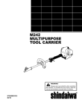
SHINDAIWA OWNER’S/OPERATOR’S MANUAL M231 MULTIPURPOSE TOOL CARRIER M231 WARNING! Minimize the risk of injury to yourself and others! Read this manual and familiarize yourself with the contents. Always wear eye and hearing protection when operating this unit. ® Part Number 65008-94011 Rev. 12/05 Introduction The Shindaiwa 231-series of handheld power tools has been designed and built to deliver superior performance and reliability without compromise to quality, comfort, safety or durability. Shindaiwa engines represent the leading edge of high-performance engine technology, delivering exceptionally high power with remarkably low displacement and weight. As an owner/operator, you’ll soon discover for yourself why Shindaiwa is simply in a class by itself! IMPORTANT! The information contained in these instructions describes units available at the time of publication. Shindaiwa Inc. reserves the right to make changes to products without prior notice, and without obligation to make alterations to units previously manufactured. Contents PAGE Introduction............................................1 Attention Statements.............................2 General Safety Instructions..................3 Safety Labels..........................................4 Operating Precautions..........................5 Product Description..............................6 Specifications.........................................7 Assembly ...............................................8 Installing a Tool Attachment................9 Mixing Engine Fuel.............................10 Starting the Engine.............................11 Stopping the Engine............................13 Adjusting Engine Idle..........................13 Checking Unit Condition....................14 Shoulder Strap......................................14 Maintenance.........................................15 Long Term Storage..............................19 Troubleshooting Guide.......................20 WARNING! The engine exhaust from this product contains chemicals known to the State of California to cause cancer, birth defects or other reproductive harm. 1 Emission System Warranty.................24 Attention Statements WARNING! A statement preceded by the triangular attention symbol and the word “WARNING” contains information that should be acted upon to prevent serious bodily injury. CAUTION! A statement preceded by the word “CAUTION” contains information that should be acted upon to prevent mechanical damage. IMPORTANT! A statement preceded by the word “IMPORTANT” is one that possesses special significance. NOTE: A statement preceded by the word “NOTE” contains information that is handy to know and may make your job easier. IMPORTANT! The operational procedures described in this manual are intended to help you get the most from your unit as well as to protect you and others from harm. These procedures are guidelines for safe operation under most conditions, and are not intended to replace any safety rules and/or laws that may be in force in your area. If you have questions regarding your 231-series power tool, or if you do not understand something in this manual, your Shindaiwa dealer will be glad to assist you. You may also contact Shindaiwa, Inc. at the address printed on the back of this manual. Read and follow this manual, make sure anyone using the trimmer does likewise. Failure to do so could result in serious personal injury or machine failure. Keep this manual for future reference. Always wear a hard hat to reduce the risk of head injuries during operation of this machine. In addition, always wear eye and hearing protection. Shindaiwa recommends wearing a face shield as additional face and eye protection. Wear heavy duty, non-slip gloves. Safety tip shoes or boots with non-slip sole should be worn. This product conducts electricity. Keep the product and/or operator a minimum distance of 15 feet (4.5 meters) away from electrical sources and power lines. Keep bystanders at least 50 feet (15 meters) away from the operating trimmer to reduce the risk of being struck by falling objects or thrown debris. The blades / cutting attachments are SHARP! Handle with care. Be aware of the danger of falling debris. 2 SAFETY Throughout this manual are special “attention statements”. SAFETY General Safety Instructions Work Safely Attachments for this M231 Multipurpose Tool Carrier operate at very high speeds and can do serious damage or injury if they are misused or abused. Never allow a person without training or instruction to operate your unit! WARNING! Use Good Judgment ALWAYS wear eye protection to shield against thrown objects. ALWAYS protect yourself from hazards such as thorny brush WARNING! and flying debris by wearing Never make unauthorized gloves and close fitting clothattachment installations. ing that covers arms and legs. Never wear shorts. Don’t wear Stay Alert loose clothing or items such as You must be physically and mentally fit jewelry that could get caught to operate this unit safely. in machinery or underbrush. DO NOT OPERATE THISlong UNIT� hair so it is above Secure IF YOU ARE TIRED, ILL OR� level. UNDER THEshoulder INFLUENCE OF� � ALCOHOL, DRUGS, OR� WARNING! NEVER run the engine when MEDICATION.� Never operate power equipment of �� transporting the unit. any kind if you are tired or if you are � NEVER operate the engine inunder the influence of alcohol, drugs, doors! Make sure there is always medication or any other substance that good ventilation. Fumes from could affect your ability or judgement. engine exhaust can cause serious injury or death. WARNING! ALWAYS clear your work area Minimize the Risk of Fire of trash or hidden debris that could be thrown back at you or NEVER smoke or light fires near toward a bystander. the engine. ALWAYS use the proper cutting ALWAYS stop the engine and allow tool for the job. it to cool before refueling. Avoid ALWAYS stop the unit imoverfilling and wipe off any fuel that mediately if it suddenly begins may have spilled. to vibrate or shake. Inspect for ALWAYS inspect the unit for fuel broken, missing or improperly leaks before each use. During each installed parts or attachments. refill, check that no fuel leaks from ALWAYS keep the unit as clean around the fuel cap and/or fuel tank. as practical. Keep it free of loose If fuel leaks are evident, stop using vegetation, mud, etc. the unit immediately. Fuel leaks must ALWAYS hold the unit firmly be repaired before using the unit. with both hands when cutting or ALWAYS move the unit to a place trimming, and maintain control at well away from a fuel storage area all times. or other readily flammable materials ALWAYS keep the handles before starting the engine. clean. NEVER place flammable material ALWAYS disconnect the spark close to the engine muffler. plug wire before performing any maintenance work. NEVER run the engine without the spark arrester screen in place. 3 Safety Labels SAFETY IMPORTANT! Safety and Operation Information Labels: Make sure all information labels are undamaged and readable. Immediately replace damaged or missing information labels. New labels are available from your local authorized Shindaiwa dealer. M231 Figure 1 4 SAFETY Operating Precautions WARNING! Always make sure the cutting attachment tool is properly installed and firmly tightened before operation. Never use a cracked or warped cutting attachment: replace it with a serviceable one and make sure it fits properly. Keep the unit away from excessive heat. Engine fuel is very flammable and fire could lead to serious personal injury or property damage. Make sure there are no missing or loose fasteners, and that the stop switch and throttle controls are working properly. CAUTION! Never extend trimming line beyond the length specified for your unit. Always keep the unit as clean as practical. Keep it free of loose vegetation, mud, etc. 5 Before starting the engine, make sure the cutting attachment is not contacting anything. Always stop the engine immediately and check for damage if you strike a foreign object or if the unit becomes tangled. Do not operate with broken or damaged equipment. Never transport the unit or set it down with the engine running. An engine that’s running could be accidently accelerated causing the cutting attachment to rotate. Make sure cutter safety guards are in place when transporting the unit. Product Description M231 Multipurpose Tool Carrier Spark Plug Throttle Lockout Lever Outer Tube Grip Handle DESCRIPTION Ignition Switch Air Cleaner Coupler Throttle Trigger Tank Guard Latch protector Fuel Tank Latch Coupler Screw Knob Figure 2 Using the accompanying illustrations as a guide, familiarize yourself with your unit and its various components. Understanding your unit helps ensure top performance, long service life, and safer operation. See Figure 2 and 2a. Figure 2a M23002a WARNING! Do not make unauthorized modifications or alterations to any of these units or their components. 6 DESCRIPTION Specifications M231 Multipurpose Tool Carrier dry weight (less attachments)....... 4.5 kg/9.8 lb. Engine model.................................................................................. Shindaiwa S230C Engine type.........................................................2-cycle,vertical-cylinder, air-cooled Bore x stroke....................................................................32 x 28 mm/1.26 x 1.10 in. Displacement . ................................................................................22.5 cc/1.4 cu. in. Maximum power................................................ 0.8 kW/1.1 HP@ 7500 rpm (min-1) Fuel/oil ratio............ 50:1 with ISO-L-EGD or JASO FC class 2-cycle Mixing Oil* Fuel tank capacity...............................................................................670 ml/22.7 oz. Carburetor type.................................................... Walbro WYL-122 diaphragm-type Muffler.............................................................................................. 2-Stage, Catalyst Ignition....................................................One-piece electronic transistor-controlled Spark plug.............................................................................................Champion CJ8 for EMC compliance use NGK BMR6A Air cleaner type............................................. Non-reversible flocked filter element Starting method................................................................................................. Recoil Stopping method...................................................................................... Slide switch Transmission type........................................................ Automatic centrifugal clutch Optional Assessories...........................................................................Shoulder strap EPA Emission Compliance Period*........................................................ Category A * The EPA emission compliance referred to on the emission compliance label located on the engine, indicates the number of operating hours for which the engine has been shown to meet Federal emission requirements. Category C = 50 hours (Moderate), B = 125 hours (Intermediate) and A = 300 hours (Extended). Specifications are subject to change without notice. meets or exceeds these specifications and is recommended for all Shindaiwa products. Prior to Assembly Before assembling, make sure you have all the components required for a complete unit: Engine/Outer tube assembly Carefully inspect all components for damage. IMPORTANT! The terms “left”, “left-hand”, and “LH”; “right”, “right-hand”, and “RH”; “front” Handle and “rear” refer to directions as viewed Kit containing handle mounting bracket and hardware, this owner’s/ by the operator during normal operation. operator’s manual and tool kit for routine maintenance. Tool kits vary by model and may include a hex wrench, spark plug/screwdriver combination wrench, and spanner wrench. 7 Assembly Handle Socket-head Capscrews Throttle Assembly Handle ASSEMBLY Outer Tube Mounting Bracket Figure 3 Connect the Handle to the Outer Tube. 1. Position the handle on the outer tube as shown. See Figure 3. 2. Install the mounting bracket with the socket head cap screws. Tighten the screws finger-tight ONLY at this time. 3. Locate the handle in the best position for operator comfort (usually about 10 inches ahead of the throttle assembly). 4. Secure the handle by alternately tightening the four socket-head screws in a diagonal or “criss-cross” fashion. 8 Installing a Tool Attachment 4. When the two tube halves are 1. Place the M231 Multipurpose Tool locked together, press down on the Carrier and the Tool Assembly on spring-loaded latch protector and a clean, flat surface so that both tighten the coupler screw knob. assemblies fit end to end. The M231 See Figure 5. assembly should be facing up, and the tool assembly should be posiCoupler Latch Protector tioned with the locking hole in the (lowered) tube end facing up. See Figure 4. ASSEMBLY CAUTION! Keep the open ends of the tubes clean and free of impurities! 2. Slip off the protective covers from the ends of both tubes, and loosen the coupler screw knob. 3. Insert the upper tube assembly into the coupler, with the tool decal facing up, until the line of the decal is flush with the end of the coupler. Twist the tool back and forth until you are sure it snaps in place by the coupler latch. See Figure 4. M231 Tube Assembly Latch Protector (extended) Latch Locking Hole M23005 Coupler Screw Knob Figure 5 Removing a Tool Attachment 1. With the unit on a clean, flat surface, loosen the coupler screw knob. The spring-loaded coupler protector should pop up. 2. Press down on the latch with your finger or thumb. This releases the coupler lock. See Figure 6. 3. Pull the tool assembly out of the coupler. Press Latch � Coupler Screw Knob M23004 Coupler Tool Assembly Figure 4 M23006 Figure 6 9 � Mixing Fuel CAUTION! Some types of gasoline contain alcohol as an oxygenate. Oxygenated gasoline may cause increased operating temperatures. Under certain conditions, alcoholbased gasoline may also reduce the lubricating qualities of some 2-cycle mixing oils. Never use any type of gasoline containing more than 10% alcohol by volume! Generic oils and some outboard oils may not be intended for use in high-performance 2-cycle type engines, and should never be used in your Shindaiwa engine. CAUTION! WARNING! Minimize the risk of fire! STOP engine before refueling. ALWAYS allow the engine to cool before refueling! Wipe all spilled fuel and move the engine at least 10 feet (3 meters) from the fueling point and source before restarting! NEVER start or operate this unit if there is a fuel leak. NEVER start or operate this unit if the carburetor, fuel lines, fuel tank and/or fuel tank cap are damaged. NEVER smoke or light any fires near the engine or fuel source! NEVER place any flammable material near the engine muffler! NEVER operate the engine without the muffler and spark arrester in good working condition. 1. Place the unit on a flat, level surface. Use only fresh, clean unleaded gasoline with a pump octane of 87 or higher. Mix all fuel with a 2-cycle air-cooled mixing oil that meets or exceeds ISO-L-EGD and/or JASO FC classified oils at 50:1 gasoline/oil ratio. 2. Clear any dirt or other debris from around the fuel filler cap. Examples of 50:1 mixing quantities Oil is a registered JASO FC classified oil and also meets or exceeds ISO-L-EGD performance requirements. Shindaiwa One is recommended for use in all Shindaiwa low emissions engines. Shindaiwa One also includes a fuel stabilizer. 1 gallon of gasoline to 2.6 oz. mixing oil 5 liters of gasoline to 100 ml. mixing oil IMPORTANT! Mix only enough fuel for your immediate needs! If fuel must be stored longer than 30 days and oil with fuel stabilizer is not used, it should first be treated with a fuel stabilizer such as StaBil™. 3. Remove the fuel cap, and fill the tank with clean, fresh fuel. 4. Reinstall the fuel filler cap and tighten firmly. 10 OPERATION This engine is designed to operate on a 50:1 mixture consisting of unleaded gasoline and ISO-L-EGD or JASO FC class 2-cycle mixing oil only. Use of non-approved mixing oils can lead to excessive carbon deposits. Filling the Fuel Tank Starting the Engine IMPORTANT! Engine ignition is controlled by a two position switch mounted on the throttle housing labeled: “I” for ON or START and “O” for OFF or STOP. 23122 Figure 7 Figure 9 1. Slide the ignition switch to the “I” position (engine ON). 3. Set the choke lever to the CLOSED position if engine is cold. Return Tube OPERATION Make sure the cutting head is clear of obstructions! Primer Bulb Figure 8 2. Press the primer bulb until fuel can be seen flowing in the transparent return tube. IMPORTANT! The primer system only pushes fuel through the carburetor. Repeatedly pressing the primer bulb will not flood the engine with fuel. 11 Figure 10 4. While holding the outer tube firmly with one hand, slowly pull the recoil starter handle until resistance is felt, then pull quickly to start the engine. CAUTION! Do not pull the recoil starter to the end of the rope travel. Pulling the recoil starter to the end of the rope travel can damage the starter. Starting the Engine (Continued) WARNING! The cutting attachment may rotate when the engine is started! 5. When the engine starts, slowly move the choke lever to the “OPEN” position. See Figure 11. (If the engine stops after the initial start, close the choke and restart.) IMPORTANT! If the engine fails to start after several attempts with the choke in the closed position, the engine may be flooded with fuel. If flooding is suspected, move the choke lever to the open position and repeatedly pull the recoil starter to remove excess fuel and start the engine. If the engine still fails to start, refer to the troubleshooting section of this manual. When the Engine Starts... After the engine starts, allow the engine to warm up at idle 2 or 3 minutes before operating the unit. Open After the engine is warm, pick up the unit and clip on the harness if so equipped. See page 14. Figure 11 WARNING! Never start the engine from the operating position. OPERATION 23122 Advancing the throttle makes the cutting attachment turn faster; releasing the throttle permits the attachment to stop turning. If the cutting attachment continues to rotate when the engine returns to idle, carburetor idle speed should be adjusted (see the next page). 12 Stopping the Engine Adjusting Engine Idle Idle Adjusting Screw Faster Slower Figure 12 Idle the engine briefly before stopping (about 2 minutes), then slide the ignition switch to the “O” (engine OFF) position. See Figure 12. Figure 13 The engine must return to idle speed whenever the throttle lever is released. Idle speed is adjustable, and must be set low enough to permit the engine clutch to disengage the cutting attachment. OPERATION WARNING! The cutting attachment must NEVER rotate at engine idle! If the idle speed cannot be adjusted by the procedure described here, return the unit to your Shindaiwa dealer for inspection. Idle Speed Adjustment 1. Place the unit on the ground, then start the engine and allow it to idle 2-3 minutes until warm. 2. If the attachment rotates when the engine is at idle, reduce the idle speed by turning the idle adjustment screw counter-clockwise. See Figure 13. 3. If a tachometer is available, the engine idle speed should be final adjusted to 2,750 (±250) rpm (min-1). 4. Carburetor fuel mixture adjustments are preset at factory and cannot be serviced in the field. 13 Checking Unit Condition Shoulder Strap WARNING! A cutting attachment shield or other protective device is no guarantee of protection against ricochet. YOU MUST ALWAYS GUARD AGAINST FLYING DEBRIS! Use only authorized Shindaiwa parts and accessories with your Shindaiwa unit. Do not make modifications to your unit without the written approval of Shindaiwa, Inc. Adjust the shoulder strap so the shoulder pad rests comfortably on the off-side shoulder with the cutting attachment parallel to the ground. Make sure all hooks and adjusting devices are secure. NOTE: Although not required for use with Multipurpose Tool Carrier, an optional shoulder strap can increase operator comfort during extended periods of operation. ALWAYS make sure the tool is properly installed and firmly tightened before operation. NEVER use a cracked or warped cutting attachment: replace it with a serviceable one. ALWAYS stop the engine immediately and check for damage if you strike a foreign object or if the unit becomes entangled. Do not operate with broken or damaged equipment. NEVER allow the engine to run at high RPM without a load. Doing so could damage the engine. OPERATION ALWAYS make sure the cutting attachment fits properly into the appropriate cutting attachment holder. If a properly installed attachment vibrates, replace the attachment with a new one and re-check. Figure 14 Optional Accessories Shoulder Strap........... P/N 22410-17202 Hanger........................ P/N 22410-12210 Hanger Bolt............... P/N 01020-05120 Hanger Nut................ P/N 01500-05041 NEVER operate a unit with worn or damaged fasteners or attachment holders. NEVER operate the unit with the cutting attachment shield or other protective devices (ignition switch etc.) removed! 14 General Maintenance MAINTENANCE WARNING! Before performing any maintenance, repair or cleaning work on the unit, make sure the engine and cutting attachment are completely stopped. Disconnect the spark plug wire before performing service or maintnenance work. WARNING! Non-standard parts may not operate properly with your unit and may cause damage and lead to personal injury. NOTE: Using non-standard replacement parts could invalidate your Shindaiwa warranty. 15 Muffler This unit must never be operated with a faulty or missing spark arrester or muffler. Make sure the muffler is well secured and in good condition. A worn or damaged muffler is a fire hazard and may also cause hearing loss. Spark Plug MAINTENANCE IMPORTANT! MAINTENANCE, REPLACEMENT OR REPAIR OF EMISSION CONTROL DEVICES AND SYSTEMS MAY BE PERFORMED BY ANY REPAIR ESTABLISHMENT OR INDIVIDUAL; HOWEVER, WARRANTY REPAIRS MUST BE PERFORMED BY A DEALER OR SERVICE CENTER AUTHORIZED BY SHINDAIWA KOGYO CO., LTD. THE USE OF PARTS THAT ARE NOT EQUIVALENT IN PERFORMANCE AND DURABILITY TO AUTHORIZED PARTS MAY IMPAIR THE EFFECTIVENESS OF THE EMISSION CONTROL SYSTEM AND MAY HAVE A BEARING ON THE OUTCOME OF A WARRANTY CLAIM. Keep the spark plug and wire connections tight and clean. Fasteners Make sure nuts, bolts, and screws (except carburetor adjusting screws) are tight. Daily Maintenance Prior to each work day, perform the following: Remove dirt or debris from the engine, check the cooling fins and air cleaner for clogging and clean them as necessary. Carefully remove any accumulation of dirt or debris from the muffler or the fuel tank. Dirt build-up in these areas could cause engine overheating, induce premature wear, or create a fire hazard. Check for loose or missing screws or components. Make sure the cutting attachment is securely fastened. Check the entire unit for leaking fuel or grease. 10-Hour Maintenance Loosen Knob Remove and clean or replace the element Figure 15 Every 10 hours of operation (more frequently in dusty or dirty conditions): Remove the air cleaner element from the carburetor and clean it thoroughly with soap and water or compressed air. Let dry before reassembling the element. See Figure 15. CAUTION! Do not operate the unit if the air cleaner or element is damaged, or if the element is wet. 10/15-Hour Maintenance Clean the spark plug and check the gap at the electrode. 0.024 inch (0.6 mm) MAINTENANCE M23016 Figure 16 Every 10 to 15 hours of operation: Remove and clean the spark plug. Adjust the spark plug electrode gap to 0.024-inch (0.6 mm). If the plug must be replaced, use only a Champion CJ8 or equivalent type spark plug of the correct heat range. For Electromagnetic Compliance (EMC) use NGK BMR6A. See Figure 16. CAUTION! Before removing the spark plug, clean the area around the plug to prevent dirt and debris from falling into internal engine parts. 16 50-hour Maintenance Every 50 hours of operation (more frequently in dusty or dirty conditions): Remove and clean the cylinder cover and clean grass and dirt from the cylinder fins. MAINTENANCE Use a hooked wire to extract the fuel filter from inside the fuel tank. See Figure 17. Remove and replace the filter element. Before reinstalling the filter, inspect the condition of the fuel line. If damage or deterioration are noted, the M231 Multipurpose Tool Carrier should be removed from service until it can be inspected by a Shindaiwa-trained service technician. 17 CAUTION! Make sure you do not pierce the fuel line with the end of the hooked wire, the line is delicate and can be damaged easily. Hooked Wire 23138 Figure 17 Filter Element 135-hour Maintenace Every 135 hours of operation, remove and clean the muffler. WARNING! Never operate the unit with a damaged or missing muffler or spark arrester! Operating with missing or damaged exhaust components is a fire hazard and could also damage your hearing. 1. Remove the spark plug boot. 2. Remove the two 4 mm engine cover screws (located at the top of the recoil housing). 3. Loosen the 5 mm engine top cover screw (the screw is captive) and lift the cover from the engine. 5. Remove the rear muffler shield socket head screw and, while noting the orientation of parts, separate the muffler shield. See Figure 18. 6. Remove the spark arrester screen and clean with a stiff bristle brush. 7. Gently tap the muffler on a wood surface to dislodge any loose carbon. 8. Inspect the cylinder exhaust port for carbon buildup. 9. Reassemble the muffler in the reverse order of disassembly. IMPORTANT! If you note excessive carbon buildup, consult with an authorized servicing dealer. 4. Remove the two 5 mm muffler screws. Remove the lower muffler screw, then lift the muffler assembly from the engine. Rear Muffler Shield Spark Arrester Screen Forward Muffler Shield MAINTENANCE 5 mm Muffler Screws 23139 Rear Muffler Shield Screw Muffler Lower Muffler Screw Figure 18 18 Long Term Storage Whenever the unit will not be used for 30 days or longer, use the following procedures to prepare it for storage: To remove the remaining fuel from the fuel lines and carburetor and with the fuel drained from the fuel tank: Clean external parts thoroughly and apply a light coating of oil to all metal surfaces. 1. Prime the primer bulb until no more fuel is passing through. Drain all the fuel from the fuel tank. IMPORTANT! All stored fuels should be stabilized with a fuel stabilizer such as STA-BIL™, if oil with fuel stabilizer is not used. CAUTION! Gasoline stored in the carburetor for extended periods can cause hard starting and could also lead to increased service and maintenance cost. 2. Start and run the engine until it stops running. 3. Repeat steps 1 and 2 until the engine will no longer start. Remove the spark plug and pour about 1/4 ounce of 2-cycle mixing oil into the cylinder through the spark plug hole. Slowly pull the recoil starter 2 or 3 times so oil will evenly coat the interior of the engine. Reinstall the spark plug. Before storing the unit, repair or replace any worn or damaged parts. Remove the air cleaner element from the carburetor and clean it thoroughly with soap and water. Let dry and reassemble the element. MAINTENANCE Store the unit in a clean, dustfree area. 19 Troubleshooting Guide ENGINE DOES NOT START What To Check Possible Cause Remedy Faulty recoil starter. Fluid in the crankcase. Internal damage. Consult with an authorized servicing dealer. NO Loose spark plug. Excess wear or damage to cylinder, piston, rings. Tighten and re-test. Consult with an authorized servicing dealer. NO Fuel incorrect, stale, or contaminated; mixture incorrect. Refill with fresh, clean unleaded gasoline with a pump octane of 87 or higher mixed with a 2-cycle air cooled mixing oil that meets or exceeds ISO-L-EGD and/or JASO FC classified oils at 50:1 gasoline/oil ratio. NO Check for clogged fuel filter and/or vent. Clean as required; restart. The ignition switch is in “O” (OFF) position. Shorted ignition ground. Faulty ignition unit. Move switch to “I” (ON) position and re-start. Consult with an authorized servicing dealer. If the plug is wet, excess fuel may be in the cylinder. Crank the engine with the plug removed, replace the plug, and re-start. The plug is fouled or improperly gapped. Clean and re-gap the plug to 0.024 inch (0.6 mm). Re-start. The plug is damaged internally or of the wrong size. Replace the plug with a CJ8 or equivalent resistor type spark plug of the correct heat range. Set spark plug electrode gap to 0.024-0.028 inch (0.6-0.7 mm). For Electromagnetic compliance (EMC) use NGK BMR6A. Restart. Does the engine NO crank? YES Good compression? YES Does the tank contain fresh fuel of the proper grade? YES Is fuel visible and moving in the return line when priming? YES Is there spark at NO the spark plug wire terminal? YES Check the spark plug. TROUBLESHOOTING 20 Troubleshooting Guide (Continued) LOW POWER OUTPUT What To Check Is the engine overheating? Engine is rough at all speeds. May also have black smoke and/or unburned fuel at the exhaust. Possible Cause Remedy Operator is overworking the machine. Shorten trimmer line. Cut at a slower rate. Carburetor mixture is too lean. Consult with an authorized servicing dealer. Improper fuel ratio. Refill with fresh, clean unleaded gasoline with a pump octane of 87 or higher mixed with a 2-cycle air cooled mixing oil that meets or exceeds ISO-L-EGD and/or JASO FC classified oils at 50:1 gasoline/oil ratio. Fan, fan cover, cylinder fins dirty or damaged. Clean, repair or replace as necessary. Carbon deposits on the piston or in the muffler. Consult with an authorized servicing dealer. Clogged air cleaner. Service the air cleaner element. Loose or damaged spark plug. Tighten or replace. Replace the plug with a CJ8 or equivalent resistor type spark plug of the correct heat range. Set spark plug electrode gap to 0.024-0.028 inch (0.6-0.7 mm). For Electromagnetic compliance (EMC) use NGK BMR6A. Restart. Air leakage or clogged fuel line. Repair or replace filter and/or fuel line. Water in the fuel. Replace the fuel. Piston seizure. Consult with an authorized servicing dealer. Faulty carburetor and/or Consult with an authorized diaphragm. servicing dealer. TROUBLESHOOTING Engine is knocking. 21 Overheating condition. See above. Improper fuel. Check fuel octane rating; check for presence of alcohol in the fuel (pg. 10). Refuel as necessary. Carbon deposits in the combustion chamber. Consult with an authorized servicing dealer. Troubleshooting Guide (Continued) ADDITIONAL PROBLEMS Symptom Poor acceleration. Engine stops abruptly. Engine difficult to shut off. Remedy Clogged air cleaner. Clean the air cleaner element. Clogged fuel filter. Replace the fuel filter. Lean fuel/air mixture. Consult with an authorized servicing dealer. Idle speed set too low. Adjust: 2750 (±250) rpm (min-1) Switch turned off. Reset the switch and re-start. Fuel tank empty. Refuel. Clogged fuel filter. Replace filter. Water in the fuel. Refill with fresh, clean unleaded gasoline with a pump octane of 87 or higher mixed with a 2-cycle air cooled mixing oil that meets or exceeds ISO-L-EGD and/or JASO FC classified oils at 50:1 gasoline/oil ratio. Shorted spark plug or loose terminal. Tighten or replace the plug with a CJ8 or equivalent resistor type spark plug of the correct heat range. Set spark plug electrode gap to 0.024-0.028 inch (0.6-0.7 mm). For Electromagnetic compliance (EMC) use NGK BMR6A. Restart. Ignition failure. Replace the ignition unit. Piston seizure. Consult with an authorized servicing dealer. Ground (stop) wire is disconnected or switch is defective. Test and replace as required. Overheating due to incorrect spark plug. Replace the plug with a CJ8 or equivalent resistor type spark plug of the correct heat range. Set spark plug electrode gap to 0.024-0.028 inch (0.6-0.7 mm). For Electromagnetic compliance (EMC) use NGK BMR6A. Restart. Overheated engine. Idle engine until cool. Refer to page 21 (overheated engine) Engine idle too high. Set idle: 2750 (±250) rpm (min-1) Broken clutch spring or worn clutch spring boss. Replace spring/shoes as required, check idle speed. Loose attachment holder. Inspect and re-tighten holders securely. 22 TROUBLESHOOTING Cutting attachment rotates at engine idle. Possible Cause Troubleshooting Guide (Continued) ADDITIONAL PROBLEMS Symptom Excessive vibration. Possible Cause Remedy Warped or damaged attachment. Inspect and replace attachment as required. Loose gearcase. Tighten gearcase securely. Bent main shaft/worn or Inspect and replace damaged bushings. as necessary. TROUBLESHOOTING Cutting attachment will not rotate. 23 Shaft not installed in powerhead or gearcase. Inspect and reinstall as required. Broken shaft. Consult with an authorized servicing dealer. Damaged gearcase. Consult with an authorized servicing dealer. Emission System Warranty Statement Your Warranty Rights and Obligations Manufacturer’s Warranty Coverage The California Air Resources Board, the U.S. Environmental Protection Agency and Shindaiwa Kogyo Co., Ltd. are pleased to explain the emission control system warranty on your new small off-road (non-road) engine. When sold within the U.S., this engine’s emission control system is warranted for a period of two (2) years from the date this product is first delivered to the original retail purchaser. In California, new small off-road engines must be designed, built, and equipped to meet the State’s stringent anti-smog standards. In other states, new 1997 and later non-road engines must meet the Federal EPA’s stringent anti-smog standards. Shindaiwa Kogyo Co., Ltd. must warrant the emission control system on your small off-road engine for the periods of time listed below, provided there has been no abuse, neglect, or improper maintenance of your small off-road engine. Your engine emission control system includes parts such as the carburetor, the ignition system and, if equipped, the catalytic converter. These components are specifically listed below. Where a warrantable condition exists, Shindaiwa Kogyo Co., Ltd. will repair your small off-road engine at no cost to you including diagnosis, parts, and labor. During the warranty period, Shindaiwa Kogyo Co., Ltd. will, at their option, repair or replace any defective emission-related component on this engine. During the original Warranty Period, these Warranty Rights are automatically transferable to subsequent owners of this product. What is Covered by this Warranty 1. Carburetor Internal Components Throttle Valve, Needle, Jet, Metering Diaphragm 2. Ignition System Components Ignition Coil Flywheel Rotor 3. Catalytic Converter (if originally equipped) The emission control system for your particular Shindaiwa engine may also include certain related hoses and connectors. 24 Owners Warranty Responsibilities As the small off-road engine owner, you are responsible for the performance of the required maintenance listed in this owners manual. Shindaiwa Kogyo Co., Ltd. recommends that you retain all receipts covering maintenance on your small off-road engine, but Shindaiwa Kogyo Co., Ltd. cannot deny warranty solely for the lack of receipts or for your failure to ensure the performance of all scheduled maintenance. As the small off-road engine owner, you should be aware, however, that Shindaiwa Kogyo Co., Ltd. may deny you warranty coverage if your small off-road engine or a part has failed due to abuse, neglect, improper maintenance, or unapproved modifications. You are responsible for presenting your small off-road engine to an authorized Shindaiwa Dealer as soon as a problem exists. The warranty repairs should be completed in a reasonable amount of time, not to exceed 30 days. If you have any questions regarding your warranty rights and responsibilities, you should contact a Shindaiwa customer service representative at (503) 692-3070 or your local Shindaiwa Dealer. 25 Consequential Damages In the event that other component parts of this product are damaged by the failure of a warranted part, Shindaiwa Kogyo Co., Ltd. will repair or replace such component parts at no charge to you. What is Not Covered Failures caused by abuse, neglect, or improper maintenance procedures. Failures caused by the use of modified or non-approved parts or attachments. This Warranty is Administered by: Shindaiwa Inc. 11975 S.W. Herman Rd. Tualatin, OR 97062 (503) 692-3070 NOTES 26 ® Shindaiwa Inc. 11975 S.W. Herman Rd. Tualatin, Oregon 97062 USA Telephone: 503 692-3070 Fax: 503 692-6696 www.shindaiwa.com Shindaiwa Kogyo Co., Ltd. Head Office: 6-2-11, Ozuka-Nishi Asaminami-Ku, Hiroshima 731-3167, Japan Telephone: 81-82-849-2220 Fax: 81-82-849-2481 ©2005 Shindaiwa, Inc. Part Number 65008-94011 Revision 12/05 Shindaiwa is a registered trademark of Shindaiwa, Inc. Specifications subject to change without notice.