1
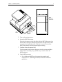
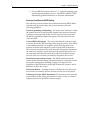
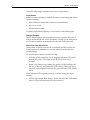
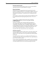
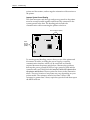
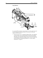
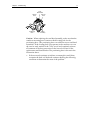
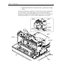
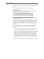
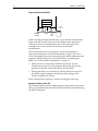
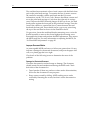
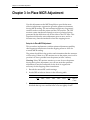
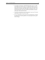
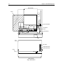
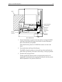
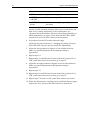
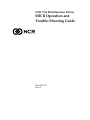
NCR 7156 Multifunction Printer
MICR Operation and
Trouble-Shooting Guide
B005-0000-1057
Issue A
The product described in this book is a licensed product of NCR Corporation.
Axiohm is the registered trademark of Axiohm.
It is the policy of NCR Corporation (NCR) to improve products as new technology, components, software,
and firmware become available. NCR, therefore, reserves the right to change specifications without prior
notice.
All features, functions, and operations described herein may not be marketed by NCR in all parts of the
world. In some instances, photographs are of equipment prototypes. Therefore, before using this document,
consult with your NCR representative or NCR office for information that is applicable and current.
To maintain the quality of our publications, we need your comments on the accuracy, clarity, organization,
and value of this book.
Address correspondence to:
Retail Solutions Group−Atlanta
NCR Corporation
2651 Satellite Blvd.
Duluth, GA 30096
Copyright © 1998
By NCR Corporation
Dayton, Ohio U.S.A.
All Rights Reserved
Written by Gary McCoy, RSG-Atlanta
MICR Operation and Trouble-Shooting Guide
i
Preface
Use this book as a reference manual and troubleshooting guide when
servicing the MICR reader. The book is intended as a guide for service
representatives, field engineers, and for anyone who will be installing
and servicing the 7156 printer. It can also be used as a reference for
service training courses. You must be an authorized, trained service
representative to service the 7156 printer.
Where to Get Additional Information
The following publications contain more information about the 7156
printer. Contact your sales representative to obtain additional copies of
this guide or any of the publications listed below.
Title
Order Number
7156 Thermal Receipt and Impact Slip Printer:
Owner’s Guide
BD20-1436A
7156 Thermal Receipt and Impact Slip Printer:
Setup and User’s Guide
BD20-1435A
7156 Thermal Receipt and Impact Slip Printer:
Service Guide
BD20-1437A
7156 Thermal Receipt and Impact Slip Printer:
Parts Identification Manual
BUF0-0104
ii
MICR Operation and Trouble-Shooting Guide
MICR Operation and Trouble-Shooting Guide
Table of Contents
Chapter 1: 7156 MICR Operation
MICR Setup and Read Test............................................... 1
Necessary Conditions for MICR Reading ...................... 4
Chapter 2: Troubleshooting
Incorrect Document Feed.................................................. 5
Printer Hookup ............................................................ 6
Damaged Document ................................................... 6
Obscured or Faulty Slip-In Sensor ............................ 6
Insert MICR Document ..................................................... 7
Document Inserted Incorrectly.................................. 8
Missing Platen Magnet ............................................... 8
Incorrect Printer Installation, Electrical Grounding
or Bonding, or MICR Adjustment ................................... 8
CRT Monitor Interference .......................................... 8
Improper System Ground Bonding .......................... 9
Faulty Read head ....................................................... 10
Degraded Buck Coil Connections ........................... 12
Faulty Amplifier, Read head, or Buck Coil............ 12
Read head Contact and Movement: Mechanical
Problems............................................................................ 14
Faulty MICR Solenoid............................................... 15
Suppressed Read head Motion................................ 16
Damaged or Missing Foam Pad .............................. 16
Read head Tilt ............................................................ 17
Improper Document Motion .......................................... 18
Damaged or Obstructed Document........................ 18
Bumps on Paper Feed Rolls ..................................... 19
iii
iv
MICR Operation and Trouble-Shooting Guide
Platen Gap Tightness ................................................ 19
Chapter 3: In-Place MICR Adjustment
Setup for In-Place MICR Adjustment ........................... 21
MICR Adjustment............................................................ 22
MICR Operation and Trouble-Shooting Guide
v
Revision Record
Issue
Date
Remarks
A
Dec 97
First printing
vi
MICR Operation and Trouble-Shooting Guide
Radio Frequency Interference Statements
Federal Communications Commission (FCC)
Information to User
This equipment has been tested and found to comply with the limits for a Class A
digital device, pursuant to Part 15 of FCC Rules. These limits are designed to provide
reasonable protection against harmful interference when the equipment is operated in
a commercial environment. This equipment generates, uses, and can radiate radio
frequency energy and, if not installed and used in accordance with the instruction
manual, may cause harmful interference to radio communications. Operation of this
equipment in a residential area is likely to cause interference in which case the user
will be required to correct the interference at his own expense.
NCR is not responsible for any radio or television interference caused by unauthorized
modification of this equipment or the substitution or attachment of connecting cables
and equipment other than those specified by NCR. The correction of interference
caused by such unauthorized modification, substitution or attachment will be the
responsibility of the user. The user is cautioned that changes or modifications not
expressly approved by NCR may void the user’s authority to operate the equipment.
Canadian Department of Communications
This digital apparatus does not exceed the Class A limits for radio noise emissions
from digital apparatus set out in the Radio Interference Regulations of the Canadian
Department of Communications.
Le présent appareil numérique n’émet pas de bruits radioélectriques dépassant les
limites applicables aux appareils numériques de la classe A prescrites dans le
Règlement sur le brouillage radioélectriques édicté par le ministrère des
Communications du Canada.
Voluntary Control Council For Interference (VCCI)
Chapter 1: 7156 MICR Operation
MICR (Magnetic Ink Character Recognition) is a feature of the 7156
printer which transforms the slight magnetic properties of specially
printed MICR characters into electrical voltage patterns. These
patterns, unique for each of the fourteen different MICR character
definitions, are translated into an electronic data image by a decoding
program residing in the printer controller. This data image is sent from
the printer to the host system in an ASCII format for transaction
processing.
The 7156 MICR is very stable and can run for the life of the printer
without readjustment of the factory settings. However, you may
encounter problems due to electromagnetic interference or changes in
the printer mechanism. If you do encounter a problem, use this guide
to help you identify the cause and the solution.
Note: A document read error of approximately 1 in 100 read attempts
during normal MICR operation is not considered to be a problem.
MICR Setup and Read Test
This section outlines the basic process for setting up and testing MICR.
1. Install printer.
Assemble the system components, placing the printer in its normal
user location. Leave at least 1 inch between the printer and any
CRT-type display.
2. Connect the power and communication cables. (Be sure both the
printer and the host are turned off.)
Some models of the 7156 printer receive power from a separate,
remote power supply; other models are powered from the host
system through the communication cable.
3. Select the MICR test document.
2
Chapter 1: 7156 MICR Operation
Select a MICR encoded bank check or similar document. Make sure
that the test document is of high quality and fits the specifications
for the printer.
4. Enable MICR reading.
MICR reading is normally initiated on command by the host
system. For test purposes, MICR may also be enabled at the printer
using a diagnostics routine. To enable MICR reading by way of
self-diagnostics, do the following:
•
Set the DIP switches as shown: (Record the current settings
first.)
Switch
•
1
2
OFF
ON
3
4
5
6
OFF OFF OFF OFF
7
8
ON Don’t
Care
Check that there is sufficient receipt paper loaded and that both
the top cover and the front cover are tightly closed.
Chapter 1: 7156 MICR Operation
3
END ORSE H ERE
RESERVED FOR FINANCIAL INSTITUTION USE
MICR
Characters
Underneath
LED
Guide
Slip
Table
Extended
Slip Table
Check Orientation
5. Turn on the printer power.
6. Insert the MICR document.
Place the document on the slip table with the MICR characters face
down and to the right. Slide the document to the right until it lines
up against the slip guide (wall). Slide the document toward the
back of the printer until the printer begins running.
7. Confirm correct document feed.
The document should almost disappear into the printer and then
feed back out smoothly, stop, and be easy to remove after the
MICR printout.
8. Check MICR printout:
•
For a diagnostic MICR test document, the number and
locations of “?” (indicating misreads) should be within the
guidelines.
4
Chapter 1: 7156 MICR Operation
•
For any MICR document, check for “?” character misreads, and
serious misread problems such as “NO MICR CHARACTERS”,
substantially garbled translation, or character substitutions.
Necessary Conditions for MICR Reading
The following section outlines the conditions that affect MICR. Make
sure that your printer has been set up and operates within the
following guidelines.
Electrical grounding and bonding: The major metal structures within
the printer must be securely bonded together and connected properly
to the host system ground. If they are not, electrical noise may enter
the MICR amplifier and distort the signals. This electrical noise can
cause misreads.
Correct MICR adjustment: The motor that feeds documents in and
out of the printer for MICR reading emits magnetic pulses. If the MICR
is not adjusted properly, the magnetic pulses from the motor may
interfere with the weak magnetic signals from the MICR characters.
This electrical interference can cause misreads. During the adjustment,
the front cover must be closed; there must be a blank document over
the read head and behind the feed rolls; and the print head carriage
must be in the exact location provided by the printer after a reset.
Read head contact and movement: The MICR read head and the
surface of the document being read must remain in continuous contact
during the reading phase. Reading accuracy will degrade if the
alignment of the read head with the MICR characters (in skew and in
both axes of tilt) is not correct.
Document Motion: Reading accuracy will degrade if the document
does not move smoothly and at a uniform velocity out of the printer.
Undamaged, in-spec MICR documents:The documents must meet the
requirements for the printer and contain no folds, creases, or random
magnetic particles in the MICR character region.
Chapter 2: Troubleshooting
5
Chapter 2: Troubleshooting
This chapter outlines the causes and solutions for the most common
MICR problems you may encounter. If you have checked the setup of
the MICR according to the information in the preceding chapter and
are still experiencing a problem, use this chapter to help you identify
and correct the problem.
This chapter covers only MICR-related problems. For all other issues,
see the 7156 Owner’s Guide or the 7156 Service Guide.
Harness conversion kit: There is a harness extension kit for dualboard printers if the repair results in the control board replacement
with a version that contains an integrated MICR amplifier. In this
situation, remove and discard the separate MICR amplifier and its
interface harness; use the harness extensions for the read head and the
buck coil to facilitate connection to the new control board if you wish
to leave the original read head and buck coil installed.
Incorrect Document Feed
One or more of the following occurs when a document is inserted:
•
Nothing happens when document is inserted.
•
The document does not feed all the way into the printer.
•
The document feeds into the printer too far (past the feed rollers).
•
The document is still being pinched by the rolls after the read
phase.
Document feed depends on a correctly setup printer and is controlled
by two optical slip-in sensors. Both sensors are located near the slip
guide wall, one in front of the feed rollers and the other behind the
feed rollers, to the left of the MICR read head. These sensors detect the
lead and trailing edge of the document during insertion and feeding.
6
Chapter 2: Troubleshooting
Check the following to determine the cause of the problem.
Printer Hookup
Before document feeding is enabled the printer control program checks
for the following:
•
Internal harness connected to their associated headers
•
All covers closed
•
Receipt paper loaded
Confirm proper harness hookup, cover closures, and loaded paper.
Damaged Document
Inspect the document. There must be no holes or notches along the 1”
margin on the MICR side of the document. A notch or hole that passes
over a sensor could be misinterpreted as the end of the document.
Obscured or Faulty Slip-In Sensor
If the printer is in diagnostic mode, reconfigure the DIP switches for
normal operation; remember to reset the printer to enable the new
switch settings.
To test the slip-in sensors, do the following:
•
With the printer turned on, check the green indicator LED on the
front of the printer. This light should be off when no slip is
inserted.
•
Insert a slip, lining it up with the slip guide wall and sliding it all
the way to the slip stop (behind the feed rollers). When the slip is
correctly and completely inserted, the green indicator LED should
be on.
If the indicator LED responds correctly, continue testing the slip-in
sensors:
•
Pull the slip straight back about 1/4 inch: the indicator LED should
turn off. (This tests the back LED slip-in sensor.)
Chapter 2: Troubleshooting
7
•
Reinsert the slip correctly so that the indicator LED turns on. Then
pull the slip straight to the left about 1/4 inch. The indicator LED
should turn off. (This tests the front LED slip-in sensor.)
Top of Printer
Back Led Sensor
(Blow Air or Wipe Clean
w/ Soft Damp Cloth)
Front Led Sensor
(Blow Air Under
Wing to Clean)
If the indicator LED does not respond correctly, remove the slip table
and open the front cover. Locate and clean the two slip-in sensors.
Blow air, use a soft damp cloth or cotton swab to remove all
accumulated dust and debris.
Repeat the steps above to test the sensors. If the results are still not
correct, replace the sensor that is not responding correctly.
Insert MICR Document
The MICR characters may not be magnetized properly. This type of
error is indicated by MICR read errors that are mostly “?” or garbage.
The misreads may be caused by either of the following.
8
Chapter 2: Troubleshooting
Document Inserted Incorrectly
Verify that the document is being inserted correctly with the MICR
characters face down. See the illustration on page 3.
Missing Platen Magnet
MICR characters are magnetized as the document feeds into the
printer by a magnet mounted in or on the platen. Open the front cover
and pass an iron object, such as a steel screwdriver blade, just above
the right end of the platen. You should notice a strong tug from the
magnet.
If the magnet is missing replace the platen. Repeat the MICR read test.
For more information on replacing the platen, see the 7156 Service
Guide.
Incorrect Printer Installation, Electrical Grounding or Bonding,
or MICR Adjustment
Difficulty in attaining “OK” during the MICR adjustment; an
unacceptable MICR read rate (a failure rate greater than 1%); or a
catastrophic read problem such as “NO MICR CHARACTERS” or
mostly garbage may indicate electrically induced problems. This type
of problem may be caused by an oversight in the initial setup, poor
electrical grounding and bonding, or electrical interference.
Check the following to determine the cause of the problem.
CRT Monitor Interference
If the host terminal includes a CRT monitor, turn off the monitor and
repeat the MICR read test. If the monitor cannot be independently
turned off, move the monitor as far as possible away from the printer
for this test.
If the MICR read test result is now acceptable, the CRT monitor was
too close to the printer. There must be at least 1 inch of space between
any CRT device and the printer.
Try new monitor positions that will be acceptable to the user and that
will provide acceptable MICR read results. Two position options that
will reduce MICR read errors are increased spacing between the
Chapter 2: Troubleshooting
9
printer and the monitor, and an angular orientation of the monitor to
the printer.
Improper System Ground Bonding
The metal structures and the logic and power grounds in the printer
must be securely bonded together and electrically connected to the
system ground at the host. The bonding path includes the
communication cable connecting the printer to the host.
Ground Testpoint (GND)
Power
Ground
Testpoint
(PGND)
To test the ground bonding, remove the top cover of the printer and
disconnect all cables, including the power supply, except the
communication interface which is to be connected as normally
required between the printer and the host. Measure the resistance
between the power ground (PGND) or logic ground (GND) and the
control board’s steel shield with the interface cable still connected to
the printer and the host. The test points are shown in the illustration
above. The exact location of test points may vary depending on your
printer model. The resistance must be less than 5 ohms; if the
resistance is greater then 5 ohms, repair the open fault and then repeat
the MICR read test.
10
Chapter 2: Troubleshooting
Faulty Read head
Print
Mechanism
Buck
Coil
Buck
Coil Leads
Read
Head
Harness
Buck
Coil
Harness
MICR
Solenoid
Harness
To test the MICR read head, locate the buck coil to the right of the read
head as shown in the illustration above. Disconnect one lead and
repeat the MICR read test.
•
If the test result is now “NO MICR CHARACTERS,” the read head
is faulty. Replace the read head assembly and perform the MICR
adjustment. Then repeat the MICR read test. For more information
on replacing the read head assembly, see the 7156 Service Guide. For
more information on adjusting the MICR, see “In-Place MICR
Adjustment” on page 20.
Chapter 2: Troubleshooting
11
Push
Read Head
Silicone
Fluid
Positioning
Boss
Silicone
Fluid
MICR
Assembly
Caution: When replacing the read head assembly, make sure that the
cantilever mounting area contains a third locating hole for the
positioning boss. This positioning boss was added to newer read head
assemblies. If the locating hole is not present in the cantilever (as was
the case for early models of the 7156), cut off and completely remove
all remnants of the boss protrusion on the lower-left corner of the
replacement read head bracket. The positioning boss is shown in the
illustration above.
•
If the test result continues to indicate a catastrophic read failure,
reconnect the buck coil lead and continue checking the following
conditions to determine the cause of the problem.
12
Chapter 2: Troubleshooting
Degraded Buck Coil Connections
Set the printer for the MICR adjustment and print out a few readings.
For more information, see “In-Place MICR Adjustment” on page 20.
Work the buck coil connections by reaching in to the harness terminals
with needle-nose pliers and working each wire back and forth about
an eighth of an inch. The wires and connectors are shown in the
illustration above. Close the cover, if open, and print out a few more
readings without touching the MICR adjustment pots. If the results
differ from the previous readings by more than two letters, replace the
buck coil and its harness. Cleaning the contacts in addition to this
connection agitation exercise may restore proper operation as a
temporary measure.
Faulty Amplifier, Read head, or Buck Coil
Unplug the read head and the buck coil from the PC board.
Reassemble the printer and run the MICR read test.
•
If the test result is “NO MICR CHARACTERS,” either the read
head or the buck coil is faulty. Check the following resistance
measurements:
•
Read head, line-to-line: 460 plus or minus 50 Ohms.
•
Buck coil, line-to-line: 5 plus or minus 1 Ohms.
Chapter 2: Troubleshooting
13
•
Read head and buck coil, leads-to-frame: greater than 10 Meg
Ohms.
Isolate and repair any connection for which the resistance varies from
the values above. Reassemble the printer and perform the MICR
adjustment. Then repeat the MICR read test. For more information on
adjusting the MICR, see “In-Place MICR Adjustment” on page 20.
MICR
Assembly
Amplifier
Board
LC Chip
J2
Interconnect
Connector
J1 Read
Head Harness
J1 Buck Coil Connector
J3
Solenoid
Connector
Amplifier
Board
Print
Mechanism
Interconnect
Connector
Cord
Keeps
Base
Motor
Harness
14
Chapter 2: Troubleshooting
J17A MICR
Buckhead
•
J17B MICR
Readhead
If the test result is not “NO MICR CHARACTERS,” either the
amplifier board or the control board is faulty. In single-board
printers, the board is a combination amplifier/control board. For
dual-board printers the MICR amplifier is a separate board behind
the cantilever. (The problem may be the interconnect harness
between the two boards in the dual-board system; check to confirm
that the harness is properly plugged in.) Replace the board
containing the MICR amplifier. For more information, see the 7156
Service Guide. Reassemble the printer and perform the MICR
adjustment. Then repeat the MICR read test. For more information
on adjusting the MICR, see “In-Place MICR Adjustment” on page
20.
Read head Contact and Movement: Mechanical Problems
An unacceptable MICR read rate; failure rate is greater than 1%; or a
catastrophic read problem such as “NO MICR CHARACTERS” or
mostly garbage may indicate faulty read head movement or a lack of
Chapter 2: Troubleshooting
15
continuous, square contact between the document and the MICR read
head.
Check the following to determine the cause of the problem.
Faulty MICR Solenoid
Set the printer DIP switches for MICR adjustment as shown below.
(Record the present DIP switch settings first.)
Switch
1
ON
2
3
4
5
6
OFF OFF OFF OFF OFF
7
8
ON Don’t
Care
Press the reset button or press the Online button off and then on again
to enable the new settings.
Open the front cover and move the print head carriage to the left. The
read head should be resting flush with the slip guide surface. Press
and release the Paper Feed button while watching the MICR read
head; As you actuate the feed button, the read head should snap up
and down.
If the read head doesn’t move, it indicates that either the read head
mechanism is jammed or the MICR solenoid has failed. Do the
following:
•
Tear down the printer to determine if the read head mechanism is
jammed. For more information, see the 7156 Service Guide.
•
If you don’t find a jam in the read head mechanism, then the MICR
solenoid has failed. Replace the MICR bracket assembly, rebuild
the printer and perform the MICR adjustment. Then repeat the
MICR read test. For more information on replacing the MICR
bracket assembly, see the 7156 Service Guide. For more information
on adjusting the MICR, see “In-Place MICR Adjustment” on page
20.
If the read head snaps up and down, continue checking the following.
16
Chapter 2: Troubleshooting
Suppressed Read head Motion
MICR
Readhead
Printhead
Carriage
Foam
Pad
While actuating the Paper Feed button, verify that the read head rises
higher than the surface of the pad on the bottom of the print head
carriage as shown in the illustration above. Move the print head
carriage closer to the read head if necessary to make this
determination.
If the read head does not rise properly, tear down the printer to
remove the interference. For more information, see the 7156 Service
Guide. Reassemble the printer, then perform the MICR adjustment and
repeat the MICR read test. For more information on adjusting the
MICR, see “In-Place MICR Adjustment” on page 20.
•
Harness dress will affect the read head movement. See the
illustration on page 13 for the optimum shape and dress of the
ground and the pair of line leads below the read head.
•
Ensure that there is no interference with the freedom of travel of
the MICR solenoid plunger, and that the three springs of the
bracket assembly are in place.
If the read head rises properly, continue checking the following.
Damaged or Missing Foam Pad
The read head presses the document against a foam pad to ensure that
there is no separation between the document and the read head during
the MICR read phase.
Chapter 2: Troubleshooting
17
Printhead
Carriage
Bottom View of
Carriage Assembly
Insert Foam Pad Here
Foam
Pad
To confirm the condition of the foam pad, open the front cover and
slide the print head carriage to the left. Press down on the paper feed
roll until it clicks and remains open. Remove the slip table and use a
flash light if necessary to examine the black foam pad on the bottom,
right rear of the print head carriage.
If the pad is missing, damaged, or partially dislodged; remove the
carriage and repair the pad or replace the print head carriage. For more
information on replacing the print head, see the 7156 Service Guide.
Reassemble the printer and perform the MICR adjustment. Then repeat
the MICR read test. For more information on adjusting the MICR, see
“In-Place MICR Adjustment” on page 20.
If the pad is in good condition, continue checking the following.
Read head Tilt
Foam
Pad
Foam
Pad
Read
Head
Good
Read
Head
Bad
18
Chapter 2: Troubleshooting
The read head must maintain a line of total contact with the black foam
pad on the print head carriage. To examine the line of contact, remove
the cantilever assembly with the read head attached. For more
information, see the 7156 Service Guide. Remove the ribbon cassette and
move the print head carriage to 1 inch from the right end of carriage
travel. Depress the MICR solenoid plunger all the way down; the read
head presses against the foam pad on the print head carriage. From the
front of the cantilever, examine the line of contact between the read
head and the foam pad. There should not be a gap at any point along
the top of the read head as shown in the illustration above.
If a gap exists, loosen the read head bracket mounting screw, twist the
bracket assembly to remove the tilt and tighten the mounting screw.
Reassemble the printer and perform the MICR adjustment. Then repeat
the MICR read test. For more information on adjusting the MICR, see
“In-Place MICR Adjustment” on page 20.
Improper Document Motion
An unacceptable MICR read rate or a failure rate greater than 1% may
indicate a damaged or obstructed document, bumps on the paper feed
rolls, or a platen gap that is too tight.
Check each of the following in turn to determine the cause of the
problem.
Damaged or Obstructed Document
Check the document for surface bumps or damage. The document
should remain flat and unobstructed during the MICR read. Check
both sides of the document for:
•
Taped patches. If there are patches or other surface discontinuities,
do not use the document for test purposes.
•
Sharp creases caused by folding: MICR reading errors can be
reduced by flattening the creases, but don’t use the document for
testing.
Chapter 2: Troubleshooting
19
Bumps on Paper Feed Rolls
Front
Cover
Pressure
Roller
Feed
Roller
Open the front cover and slowly rotate the feed and pressure rolls. As
you rotate each roll, rub the surface from end to end, checking for
bumps or high spots. Remove any significant bumps such as those
caused by paper debris buildup. Check both rolls. If bumps have been
found and removed, repeat the MICR read test.
Platen Gap Tightness
If the platen gap is too tight, it may create a drag on documents,
interfering with a smooth feed. Measure and reset the platen gap. For
more information, see the 7156 Service Guide. Perform the MICR
adjustment and repeat the MICR read test. For more information on
adjusting the MICR, see “In-Place MICR Adjustment” on page 20.
20
Chapter 2: Troubleshooting
Chapter 3: In-Place MICR Adjustment
21
Chapter 3: In-Place MICR Adjustment
Use this adjustment to the MICR amplifier to provide the most
effective interference suppression given the printer environment
during MICR reading. The environment includes any large metal
surfaces under or near the printer and the CRT monitor. The CRT
monitor creates interference through a series of polarized pulses
generated by the deflection coils on the sides of the CRT tube. This
interference affects the noise adjustment process more, and in a
different way, than the interference from the stepping motor.
Setup for In-Place MICR Adjustment
This procedure implements a resident printer adjustment capability
that suppresses interference from the stepping motor to allow for
accurate MICR reading.
The printer should be in the position and orientation that the customer
will be using. If there is a CRT monitor next to the printer, turn it off or
position it as far as possible from the printer (at least 3 inches).
Warning: If the CRT monitor remains on or too close to the printer
during the in-place adjustment, you will not attain the optimum
adjustment. It may be inadequate for the level of suppression
necessary for the stepping motor interference.
1. Record the current DIP switch settings.
2. Set the DIP switches as shown in the following table.
Switch
1
2
3
4
5
6
7
8
ON
OFF
OFF
OFF
OFF
OFF
ON
Don’t
Care
3. Check that there is sufficient receipt paper loaded for testing and
that both the top cover and the front cover are tightly closed.
22
Chapter 3: In-Place MICR Adjustment
4. Press the RESET button or press the Online button off and then on
again to enable the new DIP switch settings.
Caution: Do not move the print head carriage from the position it was
moved to by the printer upon reset. If you should move the print head
carriage before or during the adjustment, reset the printer to accurately
position the print head carriage.
MICR Adjustment
Before making the adjustment, one of the printer covers must be
removed.
Screw
Steel
Frame
Screw
Restraining
Tab
Plastic
Cover
Trim
Chapter 3: In-Place MICR Adjustment
•
For single-board printers (the MICR adjustment pots are visible
from the front), raise the front cover and remove both screws as
shown above that are securing the plastic trim to the steel frame.
Unlatch the restraining tab on the right, inside edge of the cover.
Separate the plastic cover trim from the metal frame and set the
trim aside. Close the metal frame.
•
For dual-board printers, remove the printer’s top cover. For more
information, see the 7156 Service Guide.
•
If you accidentally move the print head carriage before or during
the adjustment, reset the printer to accurately position the print
head carriage.
23
24
Chapter 3: In-Place MICR Adjustment
Top of Printer
Paper
Paper Feed Button
MICR Read
Head
Potentiometers
Led
Front
Cover
DIP Switch
Potentiometer (R8)
Potentiometer (R9)
Paper
Front of Printer
Single - Board Printer
Chapter 3: In-Place MICR Adjustment
25
Top of Printer
Paper
Paper Feed Button
Potentiometers
Shallow Pot
Deep Pot
MICR Read
Head
Carriage
Assembly
Feed Roll
Assembly
Dual - Board Printer
Led
1. Insert a blank sheet of paper in the slip station covering the MICR
read head, but behind the paper feed rollers. See the illustration
above that matches your printer.
This simulates the presence of a MICR document over the read
head.
2. Press and release the Paper Feed button.
The MICR solenoid actuates to raise and lower the read head, the
feed rollers spin briefly, and after a short delay, a receipt is printed.
3. Examine the receipt printout.
The bar graph-like printout on the receipt displays the level of
interference (mainly from the stepping motor) given by the present
MICR adjustment. The printout values are:
26
Chapter 3: In-Place MICR Adjustment
Printout Value
Meaning
“OK”
Optimum setting
“ABCDE” or
“ABCDEF”
Maximum acceptable interference
“ABCDEFG” and
greater
Interference too high; repeat adjustment
procedure
A variation of plus or minus one character from line to line is
normal. Greater variation indicates either a poor connection to the
buck coil or a faulty read head. For more information, see
“Incorrect Printer Installation, Electrical Grounding or Bonding, or
MICR Adjustment” on page 8. (First check that the CRT is either
turned off or moved at least 3 inches from the printer.)
4. Set both pots (on the PC board) to the mid-range.
Adjusting the pots is interactive—changing the setting of one pot
affects the other. The pots are not coarse/fine adjustments.
5. Adjust the first pot about 10 degrees or less in either direction.
Make very small adjustments as the optimum setting is
approached.
6. Repeat steps 2-3.
7. Repeat steps 5-6 until the best (lowest) indication is printed. If an
“OK” prints three times in succession, go to step 12.
8. Adjust the second pot about 10 degrees or less in either direction.
Make very small adjustments as the optimum setting is
approached.
9. Repeat steps 2-3.
10. Repeat steps 8-9 until the best (lowest) indication is printed. If an
“OK” prints three times in succession, go to step 12.
11. Repeat steps 5-10 until an “OK” prints three times in succession.
12. When the adjustment is complete, remove the blank sheet of paper,
replace the cover, and reset the DIP switches for normal use.
B005-0000-1057
Dec. 1998
Printed on recycled paper