1
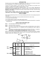
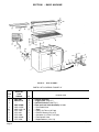
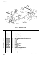
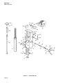
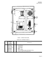
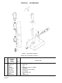
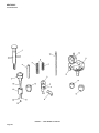
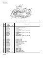
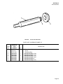
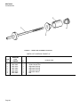
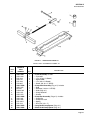
REPAIR PARTS CATALOG FOR
SUNNEN®
VALVE GUIDE & SEAT MACHINE
MODEL:
VGS-20
THIS CATALOG COVERS THE
ABOVE MODEL BETWEEN
SERIAL NO. 2163 & 2889.
“SUNNEN AND THE SUNNEN LOGO ARE REGISTERED TRADEMARKS OF SUNNEN® PRODUCTS COMPANY.”
SUNNEN® PRODUCTS COMPANY
7910 MANCHESTER AVENUE • ST. LOUIS, MO 63143, U.S.A. • PHONE: 314-781-2100
X-VGS-2009E
Like any machinery, this equipment may
be dangerous if used improperly. Be
sure to read and follow instructions for
operation of equipment.
INTRODUCTION
Illustrations show all major components in exploded detail. Item numbers on each illustration are keyed to
the corresponding parts list, providing a descriptive identification of each part.
The parts lists include assemblies as well as detail parts. An item listed without a part number can be
obtained as a component of the complete assembly of which it is a part.
Standard hardware items are listed with complete descriptions, such as Item 29 below. These may be
purchased at your local hardware store, but it is important to replace an item with one having the same
dimensions as the original. In some places brand names and part numbers are shown. These may change
depending upon availability.
Sunnen Products Company reserves the right to make changes, without notice, to materials,
specifications, colors, designs and accessories included with units.
HOW TO ORDER
When ordering replacement parts be sure to include the following information to ensure prompt shipment of
correct parts:
1. The part number and description of each part desired, obtained from this parts catalog.
2. The quantity of each part desired.
3. The voltage, frequency and phase, when ordering electrical parts.
4. The model and serial number of the machine, obtained from the name plate, where there is any question
concerning a part.
HOW TO USE THIS PARTS LIST
Step 1. – Locate desired part on illustration. Note item number.
Step 2. – Locate item number in the parts list.
Step 3. – If the item has a part number listed, order by part number and the description. A part number in
light face type indicates that it is a component of the last preceding part number in bold face
type.
Step 4. – If no number is listed, order the part number of the unit of which the desired part is a component.
ORDER ONLY BY PART NUMBER AND DESCRIPTION – NOT by item number.
NOTE: In this manual, parts may be followed by “(For CE Machines)” or “(For Non-CE Machines)” to denote
domestic machines from exported machines. The CE version is constructed to meet the requirements of the
European market, and is available to any customer.
1
Step 1.
4
2
3
15
17
14
Step 2.
Step 3.
Step 4.
ITEM
NO.
ORDER BY
PART
NUMBER
QTY.
1
2
3
4
MVH-4499A
PHSM-405
PHW-354
MVH-4422
1
3
3
1
....Spindle Cap includes
......Screw (M6 x 1 x 16 SHCS)
......Washer (M6)
....Inner Spindle Nose
14
15
16
17
PEM-870A
PEM-871
PEM-872
PHSM-600
1
1
1
1
....Cable Carrier includes
......Cable Carrier Bracket
......Cable Carrier Bracket
....Screw (M3 x 0,5 x 5mm FHCS)
DESCRIPTION
Page iii
GENERAL INFORMATION
The Sunnen® equipment has been designed and engineered for a wide variety of parts within the capacity and limitation of the equipment. With proper care
and maintenance this equipment will give years of service.
READ THE FOLLOWING INSTRUCTIONS CAREFULLY AND THOROUGHLY BEFORE UNPACKING, INSPECTING, OR INSTALLING THIS
EQUIPMENT.
IMPORTANT: Read any supplemental instructions BEFORE installing this equipment. These supplemental instructions give you important information to
assist you with the planning and installation of your Sunnen equipment.
Sunnen Technical Service Department is available to provide telephone assistance for installation, programming, & troubleshooting of your Sunnen
equipment. All support is available during normal business hours, 8:00 AM to 4:30 PM Central Time. Emergency breakdown support is available on a 24
hour / 7 day basis.
Review all literature provided with your Sunnen equipment. This literature provides valuable information for proper installation, operation, and maintenance
of your equipment. Troubleshooting information can also be found within the Instructions. If you cannot find what you need, call for technical support.
Where applicable, programming information for your Sunnen equipment is also included. Most answers can be found in the literature packaged with your
equipment.
Help us help you. When ordering parts, requesting information, or technical assistance about your equipment, please have the following
information available:
• Have ALL MANUALS on hand. The Customer Services Representative or Technician will refer to it.
• Have Model Number and Serial Number printed on your equipment Specification Nameplate.
• Where Applicable: Have Drive model and all nameplate data. Motor type, brand, and all nameplate data.
For Troubleshooting, additional information may be required:
• Power distribution information (type - delta, wye, power factor correction; other major switching devices used, voltage fluctuations)
• Installation Wiring (separation of power & control wire; wire type/class used, distance between drive and motor, grounding).
• Use of any optional devices/equipment between the Drive & motor (output chokes, etc.).
For fast service on your orders call:
Sunnen Automotive Customer Service toll free at: 1-800-772-2878
Sunnen Industrial Customer Service toll free at: 1-800-325-3670
Customers outside the USA, contact your local authorized Sunnen Distributor.
Additional information available at: http://www.sunnen.com or e-mail: [email protected]
NOTE: Sunnen reserves the right to change or revise specifications and product design in connection with any feature of our products contained herein.
Such changes do not entitle the buyer to corresponding changes, improvements, additions, or replacements for equipment, supplies or accessories
previously sold. Information contained herein is considered to be accurate based on available information at the time of printing. Should any discrepancy of
information arise, Sunnen recommends that user verify the discrepancy with Sunnen before proceeding.
ESD PREVENTION REVIEW
Let's review the basics of a sound static control system and its effective implementation. First, in the three step plan:
1.
Always ground yourself when handling sensitive components or assemblies.
2.
Always use a conductive or shielded container during storage or transportation. These materials create a Faraday
cage which will isolate the contents from static charges.
3.
Open ESD safe containers only at a static safe work station.
At the static safe work station, follow these procedures before beginning any work:
A.
Put on your wrist strap or foot grounding devices.
B.
Check all grounding cords to make sure they are properly connected to ground, ensuring the effective dissipation of static charges.
C.
Make sure that your work surface is clean and clear of unnecessary materials, particularly common plastics.
D.
Anti-static bubble wrap has been included for use at the machine when an ESD safe workstation is not available.
You are now properly grounded and ready to begin work. Following these few simple rules and using a little common sense will go a long
way toward helping you and your company in the battle against the hazards of static electricity. When you are working with ESD sensitive devices, make sure you:
GROUND
ISOLATE
NEUTRALIZE
iv
SUNNEN® LIMITED PRODUCT WARRANTY
Sunnen® Products Company and its subsidiaries (SPC) warrant that all new SPC honing machines, gaging equipment, tooling, and related equipment will
be free of defects in material and/or workmanship for a period of one year from the date of original shipment from SPC.
Upon prompt notification of a defect during the one-year period, SPC will repair, replace, or refund the purchase price, with respect to parts that prove to be
defective (as defined above). Any equipment or tooling which is found to be defective from improper use will be returned at the customer's cost or repaired
(if possible) at customer's request. Customer shall be charged current rates for all such repair.
Prior to returning any SPC product, an authorization (RMA#) and shipping instructions must be obtained from the Customer Service Department or items
sent to SPC will be returned to the customer.
Warranty Limitations and Exclusions This Warranty does not apply to the following:
• Normal maintenance items subject to wear and tear: (belts, fuses, filters, etc).
• Damages resulting from but not limited to:
› Shipment to the customer (for items delivered to customer or customer's agent F.O.B., Shipping Point)
› Incorrect installation including improper lifting, dropping and/or placement
› Incorrect electric power (beyond +/- 10% of rated voltage) including intermittent or random voltage spikes or drops
› Incorrect air supply volume and/or pressure and/or contaminated air supply
› Electromagnetic or radio frequency interference from surrounding equipment (EMI, RFI)
› Storm, lightning, flood or fire damage
› Failure to perform regular maintenance as outlined in SPC manuals
› Improper machine setup or operation causing a crash to occur
› Misapplication of the equipment
› Use of non-SPC machines, tooling, abrasive, fixturing, coolant, repair parts, or filtration
› Incorrect software installation and/or misuse
› Non-authorized customer installed electronics and/or software
› Customer modifications to SPC software
THE LIMITED WARRANTY DESCRIBED HEREIN IS EXPRESSLY IN LIEU OF ALL ANY OTHER WARRANTIES. SPC MAKES NO REPRESENTATION OR WARRANTY OF
ANY OTHER KIND, EXPRESS OR IMPLIED, WHETHER AS TO MERCHANTABILITY, FITNESS FOR A PARTICULAR PURPOSE OR ANY OTHER MATTER. SPC IS NOT
RESPONSIBLE FOR THE IMPROPER USE OF ANY OF ITS PRODUCTS. SPC SHALL NOT BE LIABLE FOR DIRECT, INDIRECT, INCIDENTAL, OR CONSEQUENTIAL
DAMAGES INCLUDING BUT NOT LIMITED TO: LOSS OF USE, REVENUE, OR PROFIT. SPC ASSUMES NO LIABILITY FOR PURCHASED ITEMS PRODUCED BY OTHER
MANUFACTURERS WHO EXTEND SEPARATE WARRANTIES. REGARDLESS OF ANY RIGHTS AFFORDED BY LAW TO BUYER, SPC's LIABILITY, IF ANY, FOR ANY AND
ALL CLAIMS FOR LOSS OR DAMAGES WITH RESPECT TO THE PRODUCTS, AND BUYER'S SOLE AND EXCLUSIVE REMEDY THEREFORE, SHALL IN ALL EVENTS BE
LIMITED IN AMOUNT TO THE PURCHASE PRICE OF THAT PORTION OF THE PRODUCTS WITH RESPECT TO WHICH A VALID CLAIM IS MADE.
Shipping Damages
Except in the case of F.O.B., Buyer's destination shipments, SPC will not be liable for any settlement claims for obvious and/or concealed shipping damages.
The customer bears the responsibility to unpack all shipments immediately and inspect for damage. When obvious and/or concealed damage is found, the
customer must immediately notify the carrier's agent to make an inspection and file a claim. The customer should retain the shipping container and packing
material.
SUNNEN® SOFTWARE LICENSE AGREEMENT
This document is a Legal Agreement between you, as user and licensee (Licensee), and Sunnen® Products Company (SPC) with respect to preprogrammed
software (Software) provided by SPC for use on SPC Equipment. By using the Software, you, as Licensee, agree to become bound by the terms of this
Agreement.
In consideration of payment of the license fee (License Fee) which is part of the price evidenced by your receipt (Receipt), SPC grants to you as Licensee
a non-exclusive right, without right to sub-license, to use the particular copy of the SPC Software licensed hereunder only on the particular equipment sold with
the Software. SPC reserves all rights including rights not otherwise expressly granted, and retain title and ownership to the Software including all subsequent copies or updates in any media. The Software and all accompanying written materials are covered by copyrights owned by SPC. If supplied on
removable media (floppy disk), you, as Licensee, may copy the Software only for back up purposes; or you may request that SPC copy the Software for you
for the same purposes. All other copying of the Software or of the accompanying written materials is expressly forbidden and is in violation of the Agreement.
The Software and accompanying written materials (including the user's manual, if any) are provided in an "as is" condition without warranty of any kind
including the implied warranties of merchantability and fitness for a particular purpose, even if SPC has been advised of this purpose. SPC specifically does
not warrant that it will be liable as a result of the operation of the Software for any direct, indirect, consequential or accidental damages arising out of the
use of or inability to use such product even if SPC has been advised of the possibility of such use. It is recognized that some states do not allow the exclusion or limitation of liability for consequential or accidental damages and to the extent this is true, the above limitations may not apply.
Any alteration or reverse engineering of the software is expressly forbidden and is in violation of this agreement.
SPC reserves the right to update the software covered by this agreement at any time without prior notice and any such updates are covered by this
agreement.
v
SAFETY INSTRUCTIONS
READ FIRST
This machine, like any equipment, may be dangerous if used improperly. Please
read all warnings and instructions before attempting to use this machine.
Always disconnect power at main enclosure before servicing machine.1
Always wear eye protection when operating this machine.
NEVER open or remove any machine cover or protective guard with power "ON."
Always disconnect power at main enclosure before servicing this equipment.1
DO NOT attempt any repair or maintenance procedure beyond those described in
this book. Contact your Sunnen® Field Service Engineer or Technical Services
Representative for repairs not covered in these instructions.
Due to the wide variety of machine configurations, all possibilities cannot be
described in these instructions. Instructions for safe use and maintenance of
optional equipment ordered through Sunnen, will be provided through separate
documentation and/or training provided by your Sunnen Field Service Engineer or
Technical Services Representative.
DO NOT attempt to defeat any safety device on this machine or on any of the
optional equipment.
If specially built automation components are added to this system, be sure that
safety is not compromised. If necessary, obtain special enlarged work area safety
system from Sunnen Products Co.
Indicates CE version ONLY.
1
DO NOT touch electrical components until main input power has been turned off and CHARGE
lamps are extinguished. WARNING: The capacitors are still charged and can be quite dangerous.
vi
CONTENTS
PAGE
Introduction ..........................................................................................................
How To Order ......................................................................................................
How To Use This Parts List .................................................................................
General Information .............................................................................................
ESD Prevention Review ......................................................................................
Limited Product Warranty ....................................................................................
Sunnen Software License Agreement ..................................................................
General Safety Instructions ..................................................................................
Contents ...............................................................................................................
iii
iii
iii
iv
iv
v
v
vi
1
SECTION I - BASIC MACHINE
A Base Assembly ....................................................................................................
B Air Float Assembly ...............................................................................................
C Head Support Fixture ..........................................................................................
D Spindle Housing ..................................................................................................
E Motor, Pulley & Belts ...........................................................................................
F Adjustable Level ..................................................................................................
G Jack Stand Assembly ..........................................................................................
H Shroud & Switches ..............................................................................................
I Electrical Enclosure .............................................................................................
2
4
6
8
10
12
13
14
15
SECTION II - ACCESSORIES
J Valve Seat Cutter Kit ...........................................................................................
K Seat Angle Cutter Kit (VGS-500) .........................................................................
L Seat Angle Cutter Kit ..........................................................................................
M Seat Angle Cutter Kit (VSC-500) .........................................................................
N Valve Seat Driver Kit ............................................................................................
O Valve Guide Installation Kit .................................................................................
P Reamer, Spotfacer Kit & Valve Guide Kit ............................................................
Q Worn Guide Alignment Fixture Kit .......................................................................
R Head Holder Frame Kit ........................................................................................
S Seat Depth Indicator ............................................................................................
16
18
20
22
23
24
25
26
27
28
“SUNNEN AND THE SUNNEN LOGO ARE REGISTERED TRADEMARKS OF SUNNEN® PRODUCTS COMPANY.”
© Copyright 2003 by Sunnen Products Company • Printed in U.S.A.
Page 1
SECTION I - BASIC MACHINE
FIGURE A – BASE ASSEMBLY
PARTS LIST COVERING FIGURE “A”
ITEM
NO.
1
2
3
-4
N/S
5
6
7
8
9
ORDER BY
PART
NUMBER
VGS-2007
PHM–371A
--VGS–2480A
VGS–1337A
VGS–1337–1A
PPP–191A
PPP–40A
PPP–238A
VGS–2484A
PPP–250A
N/S indicates Not Shown
Page 2
QTY.
1
2
1
1
1
1
2
2
1
1
1
DESCRIPTION
....Cabinet Assembly
....Trigger Latch (Pkg. of 1)
....Control Enclosure (See Fig. I)
....Float and Lock Valve Assembly includes
......Foot Pedal Valve
......Spool
......Fitting (1/4 Tube x 1/4 Pipe)
......Exhaust Silencer (Pkg. of 1)
......Connector (1/4 Tube x 1/4 Pipe)
......Flow Control Valve
......Nipple Reducer (1/4 x 1/8)
(Parts list continued on next page.)
SECTION I
BASIC MACHINE
PARTS LIST COVERING FIGURE “A” (cont’d)
ITEM
NO.
10
11
12
13
N/S
N/S
N/S
14
15
16
17
18
19
20
21
22
N/S
23
24
25
26
N/S
N/S
27
28
29
30
31
32
33
34
N/S
35
36
37
38
39
40
N/S
41
42
43
44
45
46
N/S
N/S
47
48
49
ORDER BY
PART
NUMBER
QTY.
VGS-2482A
PHS-801
PHW-308
PHS-506
LBN-451
VGS-2494A
VGS-2492A
VGS-1492A
VGS-1011A
PHN-103
VGS-2015A
KN-172
PHS-559
PHS-1019
PHW-302
PHW-390
MAN-1223
MBC-531A
MBC-531-1A
MBC-531-2A
PHS-652
PHW-118
LBN-431
PPP-167A
PPP-215A
PPP-189A
VGS-2008
VGS-2028A
PHW-390
PHW-302
MAN-1223
PHN-218
PHS-893
PHW-390
MAN-1223
VGS-1520A
VGS-1414A
VGS-1413A
KN-456
VGS-2026
VGS-2030A
MSA-219
PHW-118
LBN-401
VGS-1412A
PHS-652
PHW-118
VGS-2046A
PHS-851
VGS-2042A
1
2
2
1
1
1
2
5
5
1
2
1
1
1
2
1
1
1
1
1
2
2
2
2
1
1
1
2
2
4
2
2
8
8
8
1
1
2
1
1
2
2
2
2
1
4
4
2
4
1
DESCRIPTION
......Foot Valve Bracket with
........Screw (5/1624 x 1/2 HHCS)
........Lockwasher (5/16 Internal Tooth)
........Screw (10–32 x 3/8 PHCS)
....Lockwasher (#10 External Tooth)
....Tube (To Filter)
....Tube (To Head) (Pkg. of 1)
....Leveling Plate (Pkg. of 1)
....Leveling Screw (Pkg. of 1) with
......Nut (1/2-20 Hex Jam)
....Corner Support (Pkg. of 1) with
......Nut (5/16-18 Hex)
......Screw (5/16-18 x 1-3/4 SHCS)
....Screw (3/8-16 x 1-1/2” HHCS)
....Washer (.390 ID x 1” OD x .092)
....Washer (.406 ID x 1” OD x .156)
....Lockwasher
....Filter Regulator
....Guage
....Bracket
....Screw (1/4-20 x 1/2 BHCS)
....Lockwasher
....Nut (10-32)
....Plug (Pkg. of 1)
....Street Tee (1/4 NPT Brass)
....Elbow (1/4 Tube x 1/4 Pipe)
....Table
....Stud (Pkg. of 1)
....Washer (.406 ID x 1” OD x .156)
....Washer (.390 ID x 1” OD x .092)
....Lockwasher
....Nut (3/8-16 Hex)
....Screw (3/8-16 x 4 SHCS)
....Washer (.460 ID x 1” OD x .156)
....Lockwasher
....Tool Rack Tray
....Tool Rack Post
....Stop Collar (Pkg. of 1) with
......Setscrew (1/4-20 CPSS)
....Riser
....Stop and Clamp Assembly (Pkg. of 1) with
......Screw (1/4-20 x 1/2 HHCS)
......Lockwasher
......Washer (17/64 ID x 5/8 OD x .065)
....Support Bracket with
......Screw (1/4-20 x 1/2 BHCS)
......Lockwasher
....Clamp Bar (Pkg. of 1) with
......Screw (1/4-20 x 1/2 SHCS)
....Cover Pan
N/S indicates Not Shown
Page 3
SECTION I
BASIC MACHINE
FIGURE B - AIR FLOAT ASSEMBLY
Page 4
SECTION I
BASIC MACHINE
PARTS LIST COVERING FIGURE “B”
ITEM
NO.
-1
2
3
4
5
6
7
8
9
10
11
12
13
14
15
16
17
18
19
20
21
22
23
24
25
26
27
-28
29
30
31
32
33
34
35
36
37
38
39
40
N/S
N/S
ORDER BY
PART
NUMBER
QTY.
VGS-2440A
VGS-2442
PHP-507
PHW-307
PBR-98A
VGS-2448
PHP-597
VGS-2446A
PHS-191
PHW-306
PHS-806
VGS-2312
VGS-2314
PHS-178
PPP-243A
VGS-1026A
VGS-1027A
VGS-1028
PHN-106
VGS-1022A
PHP-416
VGS-1023A
PHM-318A
VGS-1043A
VGS-1032A
PHR-337
VGS-1031A
PHR-347
VGS-1040A
PHS-178
PG-967
VGS-1041A
VGS-1042A
PHS-579
VGS-2322
VGS-2324
VGS-2328A
VGS-2340A
VGS-2400A
VGS-2460A
PHW-306
PHN-163
VGS-2326A
VGS-2422A
1
1
2
8
6
2
2
2
2
4
4
1
16
2
5
2
2
2
2
1
2
1
1
1
1
2
1
1
1
1
1
1
1
1
1
1
4
1
1
4
4
4
1
1
DESCRIPTION
....Plate Assembly includes
......Plate
......Pin (3/16 x 5/8 Dowel)
......Washer #8 Flat)
......Bearing (Pkg. of 1)
......Spacer
......Pin (3/16 x 1-1/4 Dowel)
......Eccentric Pin (Pkg. of 1)
......Setscrew (10-32 x 1/4 Brass)
....Washer (25/64 ID x 7/8 OD x 1/8)
....Screw (3/8-24 x 3-3/4 HHCS)
....Base Assembly with
......Plug
....Setscrew (10-32 x 3/8 FPSS)
....Plug (1/16-27 Tapered) (Pkg. of 1)
....Face Clamp Pin (Pkg. of 1)
....Face Clamp Bar (Pkg. of 1) with
......Pivot Screw
......Nut (1/4-28 Hex Jam)
....Eccentric
....Pin (1/8 x 1” Spring)
....Lever
....Ball Knob
....Adjusting Screw Nut
....Adjusting Screw with
......Retaining Ring
....Adjusting Collar with
......Retaining Ring
....Knob and Handle Assembly includes
......Setscrew (10-32 x 3/8 FPSS)
......Setscrew (10-32 x 3/16 FPSS)
......Adjusting Knob
......Handle
......Screw (10-32 x 1-1/4 SHCS)
....Stud (See Fig. E)
....Nest (See Fig. E)
....Bushing (Pkg. of 1)
....Right Cylinder and Piston Assembly
....Left Cylinder and Piston Assembly
....Lever Assembly (Pkg. of 1)
....Washer (25/64 ID x 7/8 OD x 1/8)
....Nut (3/8-24 Flexloc)
....Tube (Approx. 6” Long)
....Tube (Approx. 8-1/2” Long)
N/S indicates Not Shown
NOTE: For complete Air Float Assembly order VGS-2305A. This does not include items 23 thru 33.
Page 5
SECTION I
BASIC MACHINE
FIGURE C - HEAD SUPPORT FIXTURE
PARTS LIST COVERING FIGURE “C”
ITEM
NO.
1
2
3
4
-5
6
7
8
9
N/S
10
11
12
13
14
15
16
17
18
ORDER BY
PART
NUMBER
QTY.
VGS-2062D
VGS-2551
VGS-2561
VGS-2092
PHS-805
VGS-2150A
VGS-2152A
VGS-2154A
PHM-326A
VGS-2153A
PHP-425
PF-258
PHM-327A
CK-1828
VGS-2162
VGS-1370A
PHM-325A
VGS-1394A
VGS-2087A
VGS-2086
PSP-521
1
1
1
1
1
1
1
1
1
1
1
1
1
1
1
1
2
1
1
1
1
N/S indicates Not Shown
Page 6
DESCRIPTION
....Head Support Kit includes
......Left Head Support
......Right Head Support
......Stud
......Screw (1/4-20 x 7/8 Truss Hd.)
....Bar Clamp and Adjustment Assembly includes
......Clamp
......Arm
......Knob
......Bar
......Pin (1/4 x 5/8 Spring)
......Washer (Special)
....Knob with
......Washer (Special)
......Spacer
....Angle Lock Screw Assembly with
......Ball Knob (Pkg. of 1)
....Outer Washer
....Stabilizer Latch with
......Plunger
......Spring
(Parts list continued on next
SECTION I
BASIC MACHINE
PARTS LIST COVERING FIGURE “C” (cont’d)
ITEM
NO.
ORDER BY
PART
NUMBER
QTY.
19
20
21
22
23
24
25
26
-27
28
29
30
31
32
33
34
35
36
37
38
39
40
41
42
43
44
45
46
47
48
49
50
51
52
53
54
55
PHP-423
VGS-2555A
VGS-2100A
VGS-2128A
PHS-520
VGS-2140
VGS-2262A
MBB-971
VGS-2280A
PHP-424
VGS-2284
VGS-2282
PHS-582
PHM-756
VGS-2565A
VGS-2087A
VGS-2086
PSP-521
PHP-423
VGS-1377A
VGS-2215A
VGS-1394A
VGS-1370A
PHM-325A
VGS-1390A
VGS-1395A
VGS-1398
PHR-337
VGS-1366A
PHR-347
PHM-329A
KN-180
VGS-2240A
VGS-2128A
PHS-520
VGS-2140
VGS-1487A
VGS-1488A
1
1
1
1
2
1
1
2
1
2
1
1
2
1
1
1
1
1
1
1
1
1
1
2
1
1
1
2
1
1
1
1
1
1
2
1
4
4
DESCRIPTION
......Pin (3/32 x 5/8 Spring)
....Left Swivel Clamp Assembly
....Left Head Stabilizer Assembly
....Head Stabilizer Bridge with
......Screw (8-32 x 5/8 SHCS)
......Vertical Slide Lock Screw
....Guide Rod with
......Screw (5/16-18 x 1” SHCS)
....Alignment Plate and Bar Assembly includes
......Pin (1/4 x 1-1/4 Spring)
......Alignment Plate
......Alignment Bar
......Screw (1/4-20 x 3/4 SHCS)
......Bumper
....Right Swivel Clamp Assembly
....Stabilizer Latch with
......Plunger
......Spring
......Pin (3/32 x 5/8 Spring)
....Inner Washer
....Collar and Arm Assembly
....Outer Washer
....Angle Lock Screw Assembly with
......Ball Knob (Pkg. of 1)
....Lock Collar Screw Assembly
....Stud and Nut Assembly with
......Pin
......Retaining Ring
....Pivot Block with
......Retaining Ring
....Knob with
......Setscrew (10-32 x 1/4 FPSS)
....Right Head Stabilizer Assembly
....Head Stabilizer Bridge with
......Screw (8-32 x 5/8 SHCS)
......Vertical Slide Lock Screw
....Head Clamp Spacer, Long (Pkg. of 1)
....Head Clamp Spacer, Short (Pkg. of 1)
N/S indicates Not Shown
NOTE: For complete Head Support & Stabilizer Assembly order VGS-2540A.
Page 7
SECTION I
BASIC MACHINE
FIGURE D - SPINDLE HOUSING
Page 8
SECTION I
BASIC MACHINE
PARTS LIST COVERING FIGURE “D”
ITEM
NO.
ORDER BY
PART
NUMBER
QTY.
1
2
-3
4
5
6
7
-8
9
10
11
12
13
14
15
16
17
18
19
20
21
22
23
24
-25
26
27
28
29
30
31
32
-33
34
35
36
37
38
39
40
41
42
VGS-1250A
VGS-1259A
VGS-1265A
VGS-1266A
PHS-547
PG-2372
VGS-1267
VGS-1269A
VGS-1050A
VGS-1051
PHP-596
PHP-416
VGS-1060A
VGS-1056A
PSP-520A
VGS-1057A
VGS-1065A
PHS-178
VGS-1071A
AN-320
VGS-1083A
VGS-1084A
LBA-150
PHM-318A
VGS-1023A
VGS-1082A
VGS-1275A
VGS-1276A
VGS-1277A
CK-242A
VGS-1278A
VGS-1280A
PHM-323A
LBN-309
VGS-1431A
VGS-1435A
VGS-1436A
VGS-1437A
LBN-369
VGS-1052A
VGS-1058A
VGS-1093A
PHS-506
PBR-98A
CRG-868
VGS-1285D
1
1
1
1
1
2
2
1
1
1
1
2
1
1
1
1
1
1
1
4
1
1
1
1
1
1
1
1
1
2
1
1
4
2
1
1
1
1
1
1
1
1
1
1
3
1
DESCRIPTION
....Spindle includes
......Stop Collar
....Lift Cable Plate Assembly includes
......Plate
......Screw (#2 x 1/4 RHMS)
......Setscrew (10-32 x 1/4 CPSS with Nylok)
......Pad
....Stop Plate Lock Nut
....Spindle Housing Assembly includes
......Spindle Housing
......Pin (1/2 x 1-1/4 Dowel)
......Pin (1/8 x 1” Spring)
......Control Stop Assembly
......Control Stop Latch with
........Spring
........Pin
......Lock Plate Screw Assembly
......Setscrew (10-32 x 3/8 FPSS)
......Leveling Pin with
........Setscrew (10-32 x 1/4 CPSS)
....Eccentric Stud
....Eccentric Nut
....Nut (3/8-24 Hex)
....Knob (1” Dia. with 1/4-20 Thread)
....Valve Operating Lever
....Eccentric Clamp
....Handle and Pinion Feed Assembly includes
......Pinion
......Thrust Washer
......Flange Bushing (Pkg. of 2)
......Eccentric Bushing
......Feed Handle Assembly includes
........Knob (1-1/4 Dia. with 3/8-24 Thread) (Pkg. of 1)
........Setscrew (1/4-20 x 1/2 CPSS)
....Spindle Tool Adapter
....Drawbar Knob and Nut Assembly includes
......Drawbar Nut
......Knob
......Setscrew (1/4-20 x 1/4 CPSS)
....Left Extension Block
....Right Extension Block
....Counterweight Pulley with
......Screw (10-32 x 3/8 BHCS)
......Ball Bearing
......Washer
....Spindle Counterbalance
N/S indicates Not Shown
Page 9
SECTION I
BASIC MACHINE
FIGURE E - MOTOR, PULLEYS & BELTS
Page 10
SECTION I
BASIC MACHINE
PARTS LIST COVERING FIGURE “E”
ITEM
NO.
-1
2
3
4
5
6
N/S
7
8
9
N/S
10
11
12
13
-14
15
16
17
18
19
20
21
22
23
24
25
26
27
28
29
30
31
32
33
34
35
36
37
38
39
40
41
42
43
44
45
46
ORDER BY
PART
NUMBER
QTY.
VGS-1130A
VGS-1133A
--VGS-1131A
CK-719
PBR-89A
PHR-113
PHR-301
VGS-1132
VGS-1136A
LBN-309
LBN-369
PHW-299
PHS-585
PDB-310A
PDB-309A
VGS-1120A
VGS-1122A
PBR-91A
VGS-1121A
PHS-717A
LBN-401A
VGS-1105A
AG-178
VGS-1076A
PHN-103
VGS-1077A
PHS-851
LBN-431
DL-66
MBB-856A
VGS-1147A
VGS-2324A
VGS-2322A
PMO-416A
VGS-1141A
PHS-811
PHS-640
AN-24U
PHW-299
VGS-1048A
VGS-1049A
AG-259A
CK-542
PHW-119
PHN-101
VGS-1138A
LBN-309
AG-128
VGS-1078A
1
1
1
1
2
2
2
2
1
1
2
2
2
2
1
1
1
1
1
1
1
1
1
4
1
1
1
2
1
1
1
1
1
1
1
1
4
1
1
1
1
1
1
2
2
2
1
2
1
1
DESCRIPTION
....Countershaft Assembly includes
......Pulley
......Setscrew (1/4-20 x 3/4 Knurled Cup Point)
......Shaft Assembly includes
........Key (3/16 x 3/4 Woodruff)
......Bearing (Pkg. of 1)
......Retaining Ring (Truarc #N5000-137)
......Retaining Ring (Roto Clip #SH-62ST-PA)
......Flange
......Pulley with
........Setscrew (1/4-20 x 1/2 CPSS)
........Setscrew (1/4-20 x 1/4 CPSS)
....Washer (Special)
....Screw (1/4-28 x 3/4 SHCS)
....Drive Belt
....Countershaft Belt
....Idler Pulley Assembly includes
.....Idler Hub
......Bearing
......Idler Pulley
......Screw (1/4-28 x 1-1/2 SHCS)
......Washer (1/4 IDX x 5/8)
....Drive Pulley Assembly
....Screw (10-32 x 3/8 SHCS)
....Motor Control Support with
......Nut (1/2-20 Hex Jam)
....Shroud Support Bracket
....Screw (1/4-20 x 1/2 SHCS)
....Nut (1/4-20 Hex)
....Screw (1/4-20 x 7/8 HHCS)
....Bumper
....Support Bracket Arm
....Nest
....Stud
....Motor (230/460 Volt, 60 Hz. 3 Ph.)
....Motor Mounting Plate with
......Screw (3/8-16 x 3/4 SFH.)
....Screw (1/4-28 x 5/8 SHCS)
....Screw (1/4-28 x 3/4 SHCS)
....Washer (1/4 Special)
....Adjusting Screw Nut
....Adjusting Screw Nut
....Screw
....Washer (Special)
....Washer (5/16 Lock)
....Nut (5/16-24 Hex)
....Pulley with
......SetScrew (1/4-20 x 1/2 CPSS)
....Screw (10-32 x 3/4 SHCS)
....Control Support Bracket
N/S indicates Not Shown
Page 11
SECTION I
BASIC MACHINE
FIGURE F - ADJUSTABLE LEVEL
PARTS LIST COVERING FIGURE “F”
ITEM
NO.
ORDER BY
PART
NUMBER
QTY.
-1
2
3
4
5
6
7
8
9
10
11
12
13
VGS-1450A
VGS-1451A
PSP-518A
PHS-802
VGS-1460A
PHS-188
VGS-1455A
PHS-187
PHP-595
VGS-1452A
PHP-422
AG-536
PSP-519A
PHS-802
1
1
1
2
1
1
1
1
1
1
1
4
1
1
N/S indicates Not Shown
Page 12
DESCRIPTION
....Adjustable Lever Assembly includes
......Adjustable Level Head
......Level Adjusting Spring
......Screw (8-32 x 1/8 Binding Hd.)
......Level Screw Assembly
......Setscrew (8-32 x 3/8 FPSS with Nylok)
......Vial and Sleeve Assembly with
........Setscrew (4-40 x 1/8 CPSS)
........Pin (1/8 x 7/8 Dowel)
......“V” Plate with
........Pin (3/16 x 1/2 Spring)
........Screw (4-40 x 1/2 SHCS)
......Pressure Spring with
........Screw (8-32 x 1/8 Binding Hd.)
SECTION I
BASIC MACHINE
FIGURE G - JACK STAND ASSEMBLY
PARTS LIST COVERING FIGURE “G”
ITEM
NO.
ORDER BY
PART
NUMBER
QTY.
-1
-2
3
4
5
VGS-1510A
VGS-1511A
VGS-1515A
VGS-1516A
VGS-1517A
VGS-1519A
VGS-1518A
1
1
1
1
1
1
1
DESCRIPTION
....Jack Assembly includes
......Jack Base
......Knob & Screw Set includes
........Knob
........Screw
......Short Support Plug
......Long Support Plug
N/S indicates Not Shown
Page 13
SECTION I
BASIC MACHINE
FIGURE H - SHROUD & SWITCHES
PARTS LIST COVERING FIGURE “H”
ITEM
NO.
1
2
3
4
5
6
7
N/S
8
9
N/S
10
N/S
11
12
13
14
15
-16
17
ORDER BY
PART
NUMBER
QTY.
VGS-1294A
VGS-1295A
PHS-506
LBA-451
PHM-758
VGS-1293A
PHS-506
LBA-451
L-TA-1017
PHS-506
LBA-451
PHM-328A
VGS-1720C
VGS-1715A
VGS-1695C
VGS-1700C
VGS-1705A
VGS-1710A
VGS-770
VGS-775A
VGS-780A
1
1
16
16
2
1
3
3
1
2
2
1
1
1
1
1
1
1
1
1
1
N/S indicates Not Shown
Page 14
DESCRIPTION
....Shroud Body with
......Back Cover
......Screw (10-32 x 3/8 Button Hd. Cap)
......Washer (#10 Shakeproof)
......Plug (3/8)
....Shroud with
......Screw (10-32 x 3/8 RHCS)
......Washer (#10 Shakeproof)
......Caution Label
......Screw (10-32 x 3/8 RHCS)
......Washer (#10 Shakeproof)
....Potentiometer Knob
....Potentiometer
....Reverse Switch Assembly
....Overload LED Switch Assembly
....Power On LED Switch Assembly
....Start Switch Assembly
....Stop Switch Assembly
....Guard Set (CE Machines Only) includes
......Front Guard (CE Machines Only)
......Top Guard (CE Machines Only)
SECTION I
BASIC MACHINE
FIGURE I - ELECTRICAL ENCLOSURE
PARTS LIST COVERING FIGURE “I”
ITEM
NO.
-1
2
3
4
5
6
N/S
ORDER BY
PART
NUMBER
QTY.
VGS-1540/L
PES-296A
VGS-1572A
VGS-1540-1A
PES-295A
PEF-170A
PEF-161A
PED-2061A
1
1
1
1
1
1
2
1
DESCRIPTION
....Control Enclosure includes
......Circuit Breaker
......Inverter Drive
......Power Supply
......Relay
......Fuse (.1 Amp.)
......Fuse (15 Amp.)(208 Volt, 60 Hz. Machine Only)
......Power Line Filter (“CE” Machine Only)
N/S indicates Not Shown
Page 15
SECTION II - ACCESSORIES
FIGURE J - VALVE SEAT CUTTER KIT
PARTS LIST COVERING FIGURE “J”
ITEM
NO.
-1
2
3
4
5
6
7
8
9
ORDER BY
PART
NUMBER
VGS-410A
VGS-411A
AG-9
F-406
CB-1932A
AG-128
VGS-412A
VGS-413A
AG-9
VGS-414A
N/S indicates Not Shown
Page 16
QTY.
1
1
1
1
1
1
1
1
1
1
DESCRIPTION
....Setting Fixture, English includes
......Base with
........Pin
......Setscrew (1/4-20 x 3/4 FPSS)
......Micometer
......Screw (10-32 x 3/4 SHCS)
......Locating Pin
......Spacer Ring with
........Pin
......Setting Plug
SECTION II
ACCESSORIES
PARTS LIST COVERING FIGURE “J” (cont’d)
ITEM
NO.
-1
2
3
4
5
6
7
8
9
10
11
11
11
12
12
12
12
13
14
15
16
17
18
18
18
` 18
18
18
18
18
18
19
20
21
22
23
24
24
25
ORDER BY
PART
NUMBER
QTY.
VGS-410MA
VGS-411A
AG-9
F-406
CB-1932MA
AG-128
VGS-412A
VGS-413A
AG-9
VGS-414MA
PWM-5A
VGS-325
VGS-325S
VGS-325T
ASPC-937A
ASPC-1031
ASPC-1125
ASPC-1218
ASPC-939A
--ASPC-944A
ASPC-949A
ASPC-942A
ASPC-1312
ASPC-1500
ASPC-1687
ASPC-1875
ASPC-2062
ASPC-2250
ASPC-2437
ASPC-2625
ASPC-2812
ASPC-939A
--ASPC-943A
ASPC-947A
ASPC-941A
PSP-215A
PSP-216A
VSC-509A
1
1
1
1
1
1
1
1
1
1
1
1
1
1
1
1
1
1
1
1
2
2
2
1
1
1
1
1
1
1
1
1
1
1
2
2
2
1
1
4
DESCRIPTION
....Setting Fixture, Metric includes
......Base with
........Pin
......Setscrew (1/4-20 x 3/4 FPSS)
......Micometer
......Screw (10-32 x 3/4 SHCS)
......Locating Pin
......Spacer Ring with
........Pin
......Setting Plug
....Hex “T” Wrench (3/32)
....Driver (.389 Arbor)
....Driver (.385 Arbor)
....Driver (.390 Arbor)
....Cutting Head (Range: .937 - 1.031)
....Cutting Head (Range: 1.031 - 1.125)
....Cutting Head (Range: 1.125 - 1.218)
....Cutting Head (Range: 1.218 - 1.312)
......Retention Spring
......Body
......Wedge Insert (Pkg. of 2)
......Insert Wedge Screw (Pkg. of 2)
......Carbide Insert (Pkg. of 5)
....Cutting Head (Range: 1.312 - 1.500)
....Cutting Head (Range: 1.500 - 1.687)
....Cutting Head (Range: 1.687 - 1.875)
....Cutting Head (Range: 1.875 - 2.062)
....Cutting Head (Range: 2.062 - 2.250)
....Cutting Head (Range: 2.250 - 2.437)
....Cutting Head (Range: 2.437 - 2.625)
....Cutting Head (Range: 2.625 - 2.812)
....Cutting Head (Range: 2.812 - 3.000)
......Retention Spring
......Body
......Wedge Insert (Pkg. of 1)
......Insert Wedge Screw (Pkg. of 2)
......Carbide Insert (Pkg. of 5)
....Spring (2” Long)
....Spring (3” Long)
....Spring Bushing (Pkg. of 2)
includes items 13 thru 17
includes Items 13 thru 17
includes Items 13 thru 17
includes Items 13 thru 17
includes
includes
includes
includes
includes
includes
includes
includes
includes
19
19
19
19
19
19
19
19
19
thru
thru
thru
thru
thru
thru
thru
thru
thru
23
23
23
23
23
23
23
23
23
N/S indicates Not Shown
NOTE: Item 7, VGS-413A, is used with Cutting Heads ASPC-1312 and up.
Item 9, VGS-414A, is used to set Micrometer. item 4.
NOTE: ASPC-1500, -1687, -1875, and -2062 are included with kit. All others must be ordered separately.
Page 17
SECTION II
ACCESSORIES
FIGURE K - SEAT ANGLE CUTTER KIT (VGS-500)
PARTS LIST COVERING FIGURE “K”
ITEM
NO.
-1
2
3
4
5
6
7
8
9
-10
11
12
13
ORDER BY
PART
NUMBER
VGS-600A
VGS-601
VGS-602A
VGS-603A
VGS-620A
PHS-585
VGS-611A
VGS-609A
PHS-126
VGS-608A
VGS-625A
VGS-627A
PHW-181
PHS-824
VGS-626
N/S indicates Not Shown
Page 18
QTY.
1
1
1
1
1
1
1
1
1
1
1
1
2
2
1
DESCRIPTION
....Setting Fixture (.389 / .390 Arbor) includes
......Base
......Pilot Spacer
......Pilot Clamp Bracket
......Pilot Clamp Knob
......Screw (1/4-28 x 1” SHCS)
......Setting Plate Knob
......Clamp Block
......Setscrew (1/4-28 x 1-1/4 CPSS)
......Setting Plate
......Magnetic Locator Assembly includes
........Magnet with Plates
........Lockasher (#6 External Tooth)
........Screw (6-32 x 1/2 Brass RHMS)
........Sliding Block
(Parts list continued on next
SECTION II
ACCESSORIES
PARTS LIST COVERING FIGURE “K” (cont’d)
ITEM
NO.
ORDER BY
PART
NUMBER
QTY.
14
15
16
17
-17
18
-20
21
22
23
-----24
24
25
26
26
26
26
26
26
26
26
26
26
26
26
26
26
26
26
26
26
26
26
26
26
26
26
26
27
VGS-607
VGS-635A
PHN-168
VGS-616
VGS-600SA
VGS-616S
PWM-83A
VGS-510
--VGS-512A
PHS-823
PHS-225
VGS-510S
VGS-510T
VGS-515
VGS-515S
VGS-515T
PSP-215A
PSP-216A
VSC-509A
VGS-250-00
VGS-250-15
VGS-250-30
VGS-250-45
VGS-250-60
VGS-312-00
VGS-312-15
VGS-312-30
VGS-312-45
VGS-312-60
VGS-375-00
VGS-375-15
VGS-375-30
VGS-375-45
VGS-375-60
VGS-500-00
VGS-500-15
VGS-500-30
VGS-500-45
VGS-500-60
VGS-625-00
VGS-625-15
VGS-625-30
VGS-625-45
VGS-625-60
VGS-20657
1
1
1
1
1
1
1
1
1
3
3
6
1
1
1
1
1
1
1
5
1
1
1
1
1
1
1
1
1
1
1
1
1
1
1
1
1
1
1
1
1
1
1
1
1
--
DESCRIPTION
......Stop Block
......Locator Knob
......Wing Nut (3/8-16)
......Arbor
....Setting Fixture (.385 Arbor) includes Items 1 thru 16 with
......Arbor
....Hex Wrench (1/8)
....Boring Head (For .389 Arbor) includes
......Cutter Body
......Plate (Pkg. of 1)
......Screw (2-56 x 3/8 Fil Hd. IMS)
......Setscrew (1/4-28 x 1/4 FPSS)
....Boring Head (For .385 Arbor) includes Items 20 thru 23
....Boring Head (For .390 Arbor) includes Items 20 thru 23
....Boring Head (For .389 Arbor) includes Items 20 thru 23
....Boring Head (For .385 Arbor) includes Items 20 thru 23
....Boring Head (For .390 Arbor) includes Items 20 thru 23
....Spring ( 2” Long)
....Spring (3” Long)
....Spring Bushing (Pkg. of 1)
....Seat Angle Cutter (1/4 x 0 Degree) Order Separately
....Seat Angle Cutter (1/4 x 15 Degree) Order Separately
....Seat Angle Cutter (1/4 x 30 Degree) Order Separately
....Seat Angle Cutter (1/4 x 45 Degree) Order Separately
....Seat Angle Cutter (1/4 x 60 Degree) Order Separately
....Seat Angle Cutter (5/16 x 0 Degree) Order Separately
....Seat Angle Cutter (5/16 x 15 Degree) Order Separately
....Seat Angle Cutter (5/16 x 30 Degree) Order Separately
....Seat Angle Cutter (5/16 x 45 Degree) Order Separately
....Seat Angle Cutter (5/16 x 60 Degree) Order Separately
....Seat Angle Cutter (3/8 x 0 Degree) Order Separately
....Seat Angle Cutter (3/8 x 15 Degree) Supplied With Kit
....Seat Angle Cutter (3/8 x 30 Degree) Supplied With Kit
....Seat Angle Cutter (3.8 x 45 Degree) Supplied With Kit
....Seat Angle Cutter (3/8 x 60 Degree) Supplied With Kit
....Seat Angle Cutter (1/2 x 0 Degree) Order Separately
....Seat Angle Cutter (1/2 x 15 Degree) Supplied With Kit
....Seat Angle Cutter (1/2 x 30 Degree) Supplied With Kit
....Seat Angle Cutter (1/2 x 45 Degree) Supplied With Kit
....Seat Angle Cutter (1/2 x 60 Degree) Supplied With Kit
....Seat Angle Cutter (5/8 x 0 Degree) Order Separately
....Seat Angle Cutter (5/8 x 15 Degree) Order Separately
....Seat Angle Cutter (5/8 x 30 Degree) Order Separately
....Seat Angle Cutter (5/8 x 45 Degree) Order Separately
....Seat Angle Cutter (5/8 x 60 Degree) Order Separately
....Cutting Oil (Quart)
N/S indicates Not Shown
Page 19
SECTION II
ACCESSORIES
FIGURE L - SEAT ANGLE CUTTER KIT
Page 20
SECTION II
ACCESSORIES
PARTS LIST COVERING FIGURE “L”
ITEM
NO.
ORDER BY
PART
NUMBER
QTY.
1
-2
3
4
5
4
6
7
8
9
9
10
-11
12
13
14
15
-11
12
13
14
15
16
17
-18
19
20
21
22
--VSC-700
VSC-780A
PSP-213A
VSC-709A
PSP-212A
VSC-709A
VSC-710A
VSC-202A
ASPC-947A
VSC-717
VSC-718
--VSC-750
VSC-760
VSC-752A
PHM-330A
VS-87544
VS-100044
VSC-750M
VSC-760M
VSC-752MA
PHM-330A
VS-87544
VS-100044
VSC-770A
VSC-725A
ASPC-937A
ASPC-939A
ASPC-938
ASPC-949A
ASPC-944A
ASPC-942A
1
1
1
1
2
1
2
1
1
1
1
1
1
1
1
1
1
1
1
1
1
1
1
1
1
1
1
1
1
1
2
2
2
DESCRIPTION
....Pilot Tool
....Seat Angle Cutter Kit (17 - 25 mm / .669 - 1.0 in.) includes
......Level Bushing
......Spring (Long) with
........Bushing (Pkg. of 2)
......Spring (Short) with
........Bushing (Pkg. of 2)
......Cutter Body Assembly includes
........Wedge
........Screw (Special)
......Cutter (1,3 mm / .051 in. Seat Width)
......Cutter (1,0 mm / .040 in. Seat Width)
....Pilot
....Runout Gage Kit includes
......Runout Gage Assembly includes
........Dial Indicator
........Knob
......Indicator Wheel (.625 - .875)
......Indicator Wheel (.625 - 1.00)
....Metric Runout Gage Kit includes
......Runout Gage Assembly includes
........Metric Dial Indicator
........Knob
......Indicator Wheel (.625 - .875 in.)
......Indicator Wheel (.625 - 1.00 in.)
....Seat Driver Ring (11/16 Dia.)
....Driver Assembly
....Cutting Head Assembly (.937 - 1.031 in.) includes
......Retention Spring
......Cutting Head
......Insert Wedge Screw (Pkg. of 2)
......Wedge Insert (Pkg. of 2)
......Carbide Insert (Pkg. of 2)
N/S indicates Not Shown
Page 21
SECTION II
ACCESSORIES
FIGURE M - SEAT ANGLE CUTTER KIT (VSC-500)
PARTS LIST COVERING FIGURE “M”
ITEM
NO.
-1
2
3
4
2
3
5
2
3
6
7
3
8
9
10
11
-12
13
14
15
16
17
N/S
18
19
20
21
N/S
N/S
ORDER BY
PART
NUMBER
QTY.
VSC-500
VSC-50
VSC-302A
ASPC-947A
VSC-305
VSC-302A
ASPC-947A
VSC-350
VSC-302A
ASPC-947A
VSC-205
VSC-202A
ASPC-947A
VSC-08030
VSC-06030
VSC-08045
VSC-06045
VSC-400
VSC-403
VSC-420A
VSC-435A
VSC-437A
VSC-438A
VSC-430A
PHW-383
VSC-426A
PSP-215A
PSP-216A
PWM-5
VSC-509A
VGS-20657
1
1
1
1
1
1
1
1
1
1
1
1
1
1
1
1
1
1
1
1
1
1
1
1
1
2
1
1
1
4
1
N/S indicates Not Shown
Page 22
DESCRIPTION
....Seat Angle Cutter Kit includes
......Tool Sharpening Fixture with
........Wedge
........Screw (Special)
......Cutter Body (38 - 52 mm / 1.5 - 20 in.) with
........Wedge
........Screw (Special)
......Cutter Body (47 - 64 mm / 1.9 - 2.5 in.) with
........Wedge
........Screw (Special)
......Cutter Body (25 - 41 mm / 1.0 - 1.6 in.) with
........Wedge
........Screw (Special)
......Cutter (15, 30, 60)
......Cutter (15, 30, 60)
......Cutter (30, 45, 60)
......Cutter (30, 45, 60)
......Setting Fixture Assembly includes
........Base
........Ball Plunger Assembly
........Pointer Adjustment Knob
........Pointer Needle
........Pointer
........Pointer Knob
........Spring Washer
........Decal (Pkg. of 2)
......Spring (2” Long)
......Spring (3” Long)
......Hex “T” Wrench (3/32)
......Spring Bushing (Pkg. of 1)
......Cutting Oil (Quart)
SECTION II
ACCESSORIES
FIGURE N - VALVE SEAT DRIVER KIT
PARTS LIST COVERING FIGURE “N”
ITEM
NO.
-1
2
3
3
3
3
3
3
ORDER BY
PART
NUMBER
VGS-440A
VGS-441
PHR-107A
VGS-451A
VGS-452A
VGS-453A
VGS-454A
VGS-455A
VGS-456A
DESCRIPTION
QTY.
1
1
1
1
1
1
1
1
1
....Driver Assembly includes
......Driver
......Retaining Ring
....Seat Driver Ring (15/16)
....Seat Driver Ring (1-1/4)
....Seat Driver Ring (1-1/2)
....Seat Driver Ring (1-3/4)
....Seat Driver Ring (2)
....Seat Driver Ring (2-1/4)
N/S indicates Not Shown
Page 23
SECTION II
ACCESSORIES
FIGURE O - VALVE GUIDE INSTALLATION KIT
PARTS LIST COVERING FIGURE “O”
ITEM
NO.
-1
2
3
4
5
5
5
5
6
7
N/S
ORDER BY
PART
NUMBER
VGS-180A
VGS-181A
VGS-183A
VGS-184A
PHS-603
VGS-191A
VGS-192A
VGS-193A
VGS-194A
VGS-216A
VGS-217A
B-200
N/S indicates Not Shown
Page 24
QTY.
1
1
1
1
1
1
1
1
1
1
1
1
DESCRIPTION
....Canted Guide Alignment Bar includes
......Guide Alignment Bar with Pin
......Spacer
......Leaf Spring
......Screw (10-32 x 3/4 RHMS)
....Guide Driver (5/16)
....Guide Driver (11/32)
....Guide Driver (3/8)
....Guide Driver (7/16)
....Air Hammer
....Air Hammer Hose
....Lubricant (Pkg. of 6)
SECTION II
ACCESSORIES
FIGURE P - REAMER, SPOTFACER KIT, & VALVE GUIDE KIT
PARTS LIST COVERING FIGURE “P”
ITEM
NO.
1
2
3
4
5
-6
7
8
9
N/S
-7
8a
9
10
10
10
10
11
11
11
11
12
12
12
12
12
ORDER BY
PART
NUMBER
QTY.
VGS-130A
VGS-132
VGS-140A
PHS-198
PWM-12A
VGS-145A
VGS-146A
AN-320
ASPC-942A
ASPC-948A
VGS-245A
VGS-246A
AN-320
ASPC-952A
ASPC-948A
VGS-171A
VGS-172A
VGS-173A
VGS-174A
VGS-161A
VGS-162A
VGS-163A
VGS-244A
VGS-151A
VGS-152A
VGS-153A
VGS-154A
VGS-243A
1
1
3
2
1
1
1
1
2
2
1
1
1
2
4
1
1
1
1
1
1
1
1
1
1
1
1
1
DESCRIPTION
....Adapter and Drill Chuck includes
......Key (Jacobs K3)
....Adapter (Pkg. of 1) with
......Setscrew (3/8-24 x 1/4 CPSS)
....Hex “T” Wrench (3/16)
....Spotfacer Assembly (3/4) includes
......Spotfacer
......Setscrew (10-32 x 1/4 CPSS)
......Carbide Insert (Pkg. of 5)
......Taper Head Wedge Screw (Pkg. of 2)
....Spotfacer Assembly (1-1/8) includes
......Spotfacer
......Setscrew (10-32 x 1/4 CPSS)
......Carbide Insert (Pkg. of 5)
......Taper Head Wedge Screw (Pkg. of 2)
....Pilot (5/16)
....Pilot (11/32)
....Pilot (3/8)
....Pilot (7/16)
....Reamer (7/16)
....Reamer (1/2)
....Reamer (5/8)
....Reamer (9/16 x .549 Pilot) Component of VGS-20518
....Drill (.427 x .341 Pilot)
....Drill (.490 x .343 Pilot)
....Drill (.490 x .371 Pilot)
....Drill (.610 x .435 Pilot)
....Drill (.550 x .341 Pilot) Component of VGS-20518
N/S indicates Not Shown
Page 25
SECTION II
ACCESSORIES
FIGURE Q - WORN GUIDE ALIGNMENT FIXTURE KIT
PARTS LIST COVERING FIGURE “Q”
ITEM
NO.
ORDER BY
PART
NUMBER
QTY.
-1
2
2
2
3
4
VGS-20524A
VGS-100A
VGS-107A
VGS-108A
VGS-109A
VGS-112A
VGS-106A
1
1
1
1
1
1
1
N/S indicates Not Shown
Page 26
DESCRIPTION
....Worn Guide Alignment Fixture includes
......Guide Locator Pilot
......Alignment Bushing
......Alignment Bushing
......Alignment Bushing
......Alignment Sleeve
......Nut
SECTION II
ACCESSORIES
FIGURE R - HEAD HOLDER FRAME KIT
PARTS LIST COVERING FIGURE “R”
ITEM
NO.
ORDER BY
PART
NUMBER
QTY.
-1
2
3
4
5
-6
7
8
9
10
-11
12
13
14
15
16
VGS-120A
VGS-1399
PHP-599
VGS-121
PHP-598
PHS-605
VGS-1470A
VGS-1472
KN-180
PHM-318A
VGS-1471
VGS-1473
VGS-1480A
VGS-1481
VGS-1482
PSP-161A
PHP-704
VGS-1487A
VGS-1488A
1
1
2
2
2
6
2
1
1
2
1
1
2
1
1
1
1
4
4
DESCRIPTION
....Frame Assembly includes
......Plate with
........Pin (5/16 x 1/2 Dowel)
......Spacer with
........Pin (3/8 x 1/2 Dowel)
......Screw (3/8-16 x 1” SHCS)
....Clamp Stud Assembly (Pkg. of 1) includes
......Stud
......Setscrew (10-32 x 1/4 FPSS)
......Knob (Pkg. of 1)
......Clamp Stud Nut
......Handle
....Clamp Bar Assembly (Pkg. of 1) includes
......Clamp Bar
......Clamp Bar Latch
......Spring
......Drive Pin (1/4 x 1”)
....Long Head Clamp Spacer (Pkg. of 1)
....Short Head Clamp Spacer (Pkg. of 1)
N/S indicates Not Shown
Page 27
SECTION II
ACCESSORIES
FIGURE S - SEAT DEPTH INDICATOR KIT
PARTS LIST COVERING FIGURE “S”
ITEM
NO.
ORDER BY
PART
NUMBER
QTY.
-1
2
3
4
5
6
7
8
9
10
-1
2
3
4
5
6
7
8
9
10
VGS-1750
VGS-1756A
PHS-653
PHW-118
VGS-1757
PHM-348A
P-144
VGS-1759A
VGS-1758
AN-320
LN-1676
VGS-1750M
VGS-1756MA
PHS-653
PHW-118
VGS-1757
PHM-348A
P-144
VGS-1759A
VGS-1758
AN-320
LN-1676
1
1
1
1
1
1
1
1
1
1
1
1
1
1
1
1
1
1
1
1
1
1
N/S indicates Not Shown
Page 28
DESCRIPTION
....Seat Depth Indicator, English includes
......Dial Indicator
......Screw (1/4-20 x 3/4 BHCS)
......Washer (1/4 Lock)
......Indicator Clamp
......Tee Knob
......Screw (10-32 x 1/2 SHCS)
......Post
......Post Support
......Setscrew (10-32 x 1/4 CPSS)
......Screw (1/4-20 x 7/8 Flat Hd.)
....Seat Depth Indicator, Metric includes
......Metric Dial Indicator
......Screw (1/4-20 x 3/4 BHCS)
......Washer (1/4 Lock)
......Indicator Clamp
......Tee Knob
......Screw (10-32 x 1/2 SHCS)
......Post
......Post Support
......Setscrew (10-32 x 1/4 CPSS)
......Screw (1/4-20 x 7/8 Flat Hd.)
Like any machinery, this equipment may be
dangerous if used improperly. Be sure to read
and follow the instructions for the operation of
the equipment.
Page 29
FRACTION / DECIMAL / MILLIMETER EQUIVALENTS CHART
INCH
FRACTION
DECIMAL
MILLIMETER
INCH
FRACTION
DECIMAL
.281250
MILLIMETER
7,1438
INCH
FRACTION
DECIMAL
21/32
MILLIMETER
....
.003937
0,1000
9/32
.656250
16,6688
....
.007874
0,2000
19/64
.296875
7,5406
....
.011811
0,3000
5/16
.312500
7,9375
....
.669291
17,0000
43/64
.671875
17,0656
1/64
.015625
0,3969
....
.314961
8,0000
11/16
.687500
17,4625
....
.015748
0,4000
21/64
.328125
8,3344
45/64
.703125
17,8594
....
.019685
0,5000
11/32
.343750
8,7313
....
.023622
0,6000
....
.354331
9,0000
....
.708661
18,0000
23/32
.718750
18,2563
....
.027559
0,7000
23/64
.359375
9,1281
47/64
.734375
18,6531
1/32
.031250
0,7938
3/8
.375000
9,5250
....
.748031
19,0000
....
.031496
0,8000
25/64
.390625
9,9219
3/4
.750000
19,0500
....
.035433
0,9000
....
.393701
10,0000
49/64
.765625
19,4469
....
.039370
1,0000
13/32
.406250
10,3188
25/32
.781250
19,8438
3/64
.046875
1,1906
27/64
.421875
10,7156
....
.787402
20,0000
1/16
.062500
1,5875
....
.433071
11,0000
51/64
.796875
20,2406
5/64
.078125
1,9844
7/16
.437500
11,1125
13/16
.812500
20,6375
....
.078740
2,0000
29/64
.453125
11,5094
....
.826772
21,0000
3/32
.093750
2,3813
15/32
.468750
11,9063
53/64
.828125
21,0344
7/64
.109375
2,7781
....
.472441
12,0000
27/32
.843750
21,4313
....
.118110
3,0000
31/64
.484375
12,3031
55/64
.859375
21,8281
1/8
.125000
3,1750
1/2
.500000
12,7000
....
.866142
22,0000
9/64
.140625
3,5719
....
.511811
13,0000
7/8
.875000
22,2250
5/32
.156250
3,9688
33/64
.515625
13,0969
57/64
.890625
22,6219
....
.157480
4,0000
17/32
.531250
13,4938
....
.905512
23,0000
11/64
.171875
4,3656
35/64
.546875
13,8906
29/32
.906250
23,0188
3/16
.187500
4,7625
....
.551181
14,0000
59/64
.921875
23,4156
....
.196850
5,0000
9/16
.562500
14,2875
15/16
.937500
23,8125
13/64
.203125
5,1594
37/64
.578125
14,6844
....
.944882
24,0000
7/32
.218750
5,5563
....
.590551
15,0000
61/64
.953125
24,2094
15/64
.234375
5,9531
19/32
.593750
15,0813
31/32
.968750
24,6063
....
.236220
6,0000
39/64
.609375
15,4781
....
.984252
25,0000
1/4
.250000
6,3500
5/8
.625000
15,8750
63/64
.984375
25,0031
17/64
.265625
6,7469
....
.629921
16,0000
1
1.000000
25,4000
....
.275591
7,0000
41/64
.640625
16,2719
1-1/16
1.062500
26,9880
FORMULAS:
MULTIPLY
INCHES (in)
FEET (ft)
x
x
BY
25.4
0.3048
=
=
TO GET
MILLIMETERS (mm)
METERS (m)
MULTIPLY
MILLIMETERS (mm)
METERS (m)
x
x
BY
0.03937
3.281
=
=
TO GET
INCHES (in)
FEET (ft)
“SUNNEN AND THE SUNNEN LOGO ARE REGISTERED TRADEMARKS OF SUNNEN® PRODUCTS COMPANY.”
Sunnen® reserves the right to change or
revise specifications and product design
in connection with any feature of our
products contained herein. Such changes
do not entitle the buyer to corresponding
changes, improvements, additions, or
replacements for equipment, supplies or
accessories previously sold. Information
contained herein is considered to be
accurate based on available information
at the time of printing. Should any
discrepancy of information arise, Sunnen
recommends that user verify discrepancy
with Sunnen before proceeding.
PRINTED IN U.S.A.
0310
SUNNEN PRODUCTS COMPANY
7910 Manchester Ave., St. Louis, MO 63143 U.S.A.
Phone: 314-781-2100
Fax: 314-781-2268
U.S.A. Toll-Free Sales and Service –
Automotive: 1-800-772-2878 • Industrial: 1-800-325-3670
International Division Fax: 314-781-6128
http://www.sunnen.com
e-mail: [email protected]
SUNNEN PRODUCTS LIMITED
No. 1 Centro, Maxted Road
Hemel Hempstead, Herts HP2 7EF ENGLAND
Phone: ++ 44 1442 39 39 39
Fax: ++ 44 1442 39 12 12
SUNNEN AG
Fabrikstrasse 1
8586 Ennetaach-Erlen, Switzerland
Phone: ++ 41 71 648 16 16
Fax: ++ 41 71 648 31 31
SHANGHAI SUNNEN MECHANICAL CO., LTD.
889 Kang Qiao East Road, PuDong
Shanghai 201319, P.R. China
Phone: 86 21 5 813 3322
Fax: 86 21 5 813 2299
SUNNEN ITALIA S.R.L.
Viale Stelvio 12/15
20021 Ospiate di Bollate (MI) Italy
Phone: 39 02 383 417 44
Fax: 39 02 383 417 50
©COPYRIGHT SUNNEN® PRODUCTS COMPANY 2003, ALL RIGHTS RESERVED