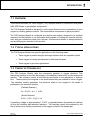
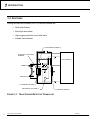
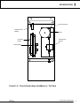
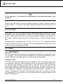
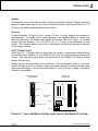
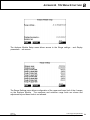
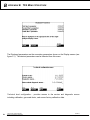
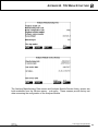
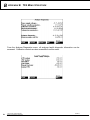
1
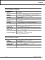
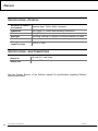
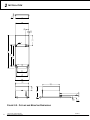
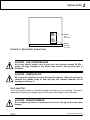
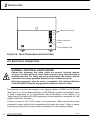
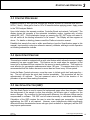
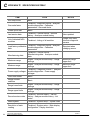
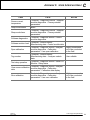
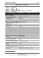
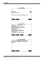
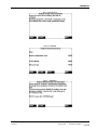
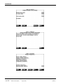
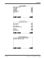
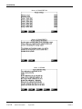
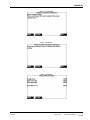
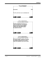
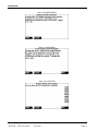
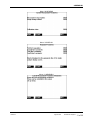
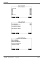
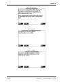
ROSEMOUNT ANALYTICAL
NGA2000
TRACE OXYGEN ANALYZER MODULE
748420-A
NOTICE
The information contained in this document is subject to change without notice.
This manual is based on the production version of the Trace Oxygen Analyzer Module. Hardware and/or
software changes may have occurred since this printing.
Rosemount Analytical's NGA 2000 system of Modular Gas Analyzers and Controllers are patented,
under U.S. Patent 5.787.015.
®
Teflon is a registered trademark of E.I. duPont de Nemours and Co., Inc.
®
SNOOP is a registered trademark of NUPRO Co.
Waferpure™ is a trademark of Millipore Corp.
®
Nanochem is a registered trademark of Semigas Corp
Manual Part Number 748420-A
August 1999
Printed in U.S.A.
Rosemount Analytical Inc.
4125 East La Palma Avenue
Anaheim, California 92807-1802
CONTENTS
PREFACE
Purpose/Safety Summary.................................................................................P1
Glossary
....................................................................................................P3
Specifications - General...................................................................................P5
Specifications - Sample ....................................................................................P5
Specifications - Physical ...................................................................................P6
Specifications - Gas Connections.....................................................................P6
Customer Service, Technical Assistance and Field Service .............................P7
Returning Parts to the Factory ..........................................................................P7
Training
....................................................................................................P7
Documentation..................................................................................................P8
Compliances ....................................................................................................P8
SECTION 1. INTRODUCTION
1.1 Overview....................................................................................................1
1.2 Typical Applications ...................................................................................1
1.3 Theory of Technology ................................................................................1
1.4 Features ....................................................................................................2
748420-A
August 1999
Trace Oxygen Analyzer Module
Rosemount Analytical NGA 2000
i
CONTENTS
SECTION 2. INSTALLATION
2.1 Unpacking ................................................................................................. 5
2.2 Assembly................................................................................................... 5
2.2.1 Electrolyte Addition ........................................................................ 5
2.3 Location .................................................................................................... 6
2.4 Gases
.................................................................................................... 6
2.4.1 Requirements ................................................................................ 6
2.4.2 Connections................................................................................... 7
2.4.3 LEAK TEST ................................................................................... 9
2.5 Electrical Connections............................................................................... 10
SECTION 3. STARTUP AND OPERATION
3.1 Overview ................................................................................................... 11
3.2 Displays .................................................................................................... 11
3.2.1 Run Mode Display ......................................................................... 11
3.2.3 Help Displays................................................................................. 14
3.3 Startup Procedure ..................................................................................... 15
3.4 Quick Start Feature ................................................................................... 15
3.5 Gas Scale Factor (GSF)............................................................................ 15
3.6 Calibration ................................................................................................. 16
3.7 Routine Operation ..................................................................................... 18
3.8 Alarm indication......................................................................................... 18
ii
Trace Oxygen Analyzer Module
Rosemount Analytical NGA 2000
748420-A
August 1999
CONTENTS
SECTION 4. MAINTENANCE AND TROUBLESHOOTING
4.1 Overview....................................................................................................19
4.1.1 Water Addition ...............................................................................20
4.2 Fuses
....................................................................................................21
4.3 Electrolyte Replacement............................................................................21
4.4 Sensor Replacement .................................................................................21
4.5 Flow Sensor Replacement.........................................................................22
4.6 Printed Circuit Boards................................................................................23
4.7 Troubleshooting .........................................................................................23
SECTION 5. REPLACEMENT PARTS
5.1 Replacement Parts ....................................................................................25
APPENDIX A. TO2 IDENTIFICATION MATRIX
APPENDIX B. TO2 MENU STRUCTURE
APPENDIX C. USER INTERFACE HELP
FACTORY CALIBRATION DATA SHEET
MATERIAL SAFETY DATA SHEET PN 748377 (SENSOR ELECTROLYTE)
GENERAL PRECAUTIONS FOR HANDLING & STORING HIGH PRESSURE CYLINDERS
WARRANTY
FIELD SERVICE AND REPAIR FACILITIES
748420-A
August 1999
Trace Oxygen Analyzer Module
Rosemount Analytical NGA 2000
iii
CONTENTS
FIGURES
1-1.
1-2.
2-1.
2-2.
2-3.
2-4.
3-1.
3-2.
3-3.
3-4.
3-5.
3-6.
4-1.
4-2.
Trace Oxygen Detector Technology........................................................... 2
Trace Oxygen Analyzer Module - Top View............................................... 3
Analyzer Module Interconnection with Instrument Platform ....................... 7
Outline and Mounting Dimensions ............................................................. 8
Back Panel Connections ............................................................................ 9
Trace Oxygen Analyzer Front Panel .......................................................... 10
Run Mode Display...................................................................................... 12
Main Menu ................................................................................................. 12
Basic Controls Menu .................................................................................. 13
Expert Controls Menu ................................................................................ 13
Analyzer Module Set-up Menu ................................................................... 14
Typical Help Menu (shown is Zero/Span Calibration Help) ........................ 14
Trace Oxygen Analyzer Sensor Assembly................................................. 20
Load Factory Calibration Data Menu.......................................................... 22
TABLES
3-1. Trace Oxygen Analyzer Module Alarms..................................................... 19
iv
Trace Oxygen Analyzer Module
Rosemount Analytical NGA 2000
748420-A
August 1999
PREFACE
PURPOSE/SAFETY SUMMARY
The purpose of this manual is to provide information concerning the components, functions,
installation and maintenance of this particular NGA 2000 module.
Some sections may describe equipment not used in your configuration. The user should become
thoroughly familiar with the operation of this module before operating it. Read this instruction
manual completely.
To avoid explosion, loss of life, personal injury and damage to this equipment
and on-site property, all personnel authorized to install, operate and service this
equipment should be thoroughly familiar with and strictly follow the instructions
in this manual. Save these instructions.
If this equipment is used in a manner not specified in these instructions,
protective systems may be impaired.
DANGER is used to indicate the presence of a hazard which will cause severe personal
injury, death, or substantial property damage if the warning is ignored
WARNING is used to indicate the presence of a hazard which can cause severe personal
injury, death, or substantial property damage if the warning is ignored.
CAUTION is used to indicate the presence of a hazard which will or can cause minor
personal injury or property damage if the warning is ignored.
NOTE is used to indicate installation, operation, or maintenance information which is
important but not hazard-related
WARNING: ELECTRICAL SHOCK HAZARD
Operate this equipment only when covers are secured. Servicing requires
access to live parts which can cause death or serious injury. Refer servicing to
qualified personnel. For safety and proper performance, this module must be
connected to a properly grounded three-wire source of electrical power.
748420-A
August 1999
Trace Oxygen Analyzer Module
Rosemount Analytical NGA 2000
P1
PREFACE
CAUTION: PARTS INTEGRITY
Tampering or unauthorized substitution of components may adversely affect
safety of this product. Use only factory documented components for repair.
CAUTION: HIGH PRESSURE GAS CYLINDERS
This analyzer requires use of pressurized gas. See General Precautions for
Handling and Storing High Pressure Cylinders, in the rear of this manual.
WARNING: CAUSTIC LIQUID
The electrolyte is a caustic solution. Review the Material Safety Data Sheet in
the rear of this manual.
WARNING: POSSIBLE EXPLOSION HAZARD
This equipment is not designed and should not be used in the analysis of
flammable samples. Use of this equipment in this way could result in explosion
and death.
P2
Trace Oxygen Analyzer Module
Rosemount Analytical NGA 2000
748420-A
August 1999
PREFACE
GLOSSARY
Analyzer Module
The module that contains all sensor/detector components for development of a Primary
Variable signal; includes all signal conditioning and temperature control circuitry.
Backplane
The interconnect circuit board which the Controller Board, Power Supply, Analyzer Module
power and network cables, I/O Modules and Expansion Modules plug into.
Control Module
The Operator Interface plus the Controller Board.
Controller Board
The computer board that serves as the Network Manager and operates the Display and
Keypad.
Distribution Assembly
The Backplane and the card cages that hold I/O and Expansion Modules.
Expansion Module
A circuit board that plugs into the Backplane from the front of the Platform and performs
special features not related to I/O functions.
I/O Module
A circuit board that plugs into the Backplane from the rear of the Platform. Has a connector
terminal for communication with external data acquisition devices and provides an
input/output function.
Operator Interface
The Display and Keyboard.
Platform
Any workable collection of the following: Controller Board, Power Supply, Distribution
Assembly, Enclosure and Operator Interface.
748420-A
August 1999
Trace Oxygen Analyzer Module
Rosemount Analytical NGA 2000
P3
PREFACE
Power Supply
Any of a variety of components that provides conditioned power to other NGA 2000
components, from the Power Supply Board that plugs into the front of the Backplane in a
stand-alone instrument to several larger ones that can power larger collections of modules
and components.
Primary Variable
The measured species concentration value from an Analyzer Module.
Secondary Variable
Data placed on the network by a module regarding current status, e.g., sample flow, source
voltage and other diagnostic information.
Softkeys
The five function keys located below the front panel display; they assume the function
displayed directly above each on the display, a function dictated by software.
System
Any collection of Analyzer Module(s), Platform(s), I/O Module(s) and Expansion Module(s).
P4
Trace Oxygen Analyzer Module
Rosemount Analytical NGA 2000
748420-A
August 1999
PREFACE
SPECIFICATIONS - GENERAL
MEASUREMENT
SPECIES
RANGES
ACCURACY
SENSITIVITY
NOISE
LINEARITY
RESPONSE TIME
ZERO DRIFT
SPAN DRIFT
EFFECT OF
TEMPERATURE
EFFECT OF FLOW
OPERATING
TEMPERATURE
POWER REQUIREMENTS
Trace Oxygen
0 to 100 ppm (output scalable down to 0-2 ppm fullscale)
±3% of reading or ±0.02% of range (except for ranges ≤ 100
ppm: ±3% of reading or ±0.05% of range)
<10 ppb Oxygen
1% of fullscale, peak to peak
±1% of fullscale
Typically 90% in less than 20 seconds
≤±1% of fullscale/24 hours at constant temperature
≤±1% of fullscale/24 hours at constant temperature
0.32% of reading per °F from 70°F
(0.58% of reading per °C from 21°C)
≤2% of reading for a flow change of ±250 cc/min (0.5 SCFH)
32°F to 113°F (0°C to 45°C)
+24 VDC ±5%, 10 W max.
Ripple and Noise: <100 mV peak to peak
Line and Load Regulations: <±1%
SPECIFICATIONS - SAMPLE
SAMPLE
Non-flammable (below 100% of the LEL)
FLOW RATE
0.5 to 1.5 L/min.
SUPPLY PRESSURE
1027 to 1082 hPa - absolute (0.2 to 1.0 psig)
TEMPERATURE
32°F to 113°F (0°C to 45°C)
PARTICULATES
filtered to <0.1 mg/L; non-condensing at ambient temperature
SAMPLE HUMIDITY
non-condensing at ambient temperatures
748420-A
August 1999
Trace Oxygen Analyzer Module
Rosemount Analytical NGA 2000
P5
PREFACE
SPECIFICATIONS - PHYSICAL
MATERIALS IN CONTACT
WITH SAMPLE
DIMENSIONS
WEIGHT
MOUNTING
CASE CLASSIFICATION
MAX. SEPARATION
FROM PLATFORM
Stainless steel, Teflon, Delrin, neoprene
See Figure 2-2, Outline and Mounting Dimensions
6.8 kg (15 lbs.)
Horizontal, external to Platform or custom installed in a panel
General Purpose for installation in weather protected area
1600 m (1 mile)
SPECIFICATIONS - GAS CONNECTIONS
SAMPLE IN
1/4 inch O.D. tube fitting
SAMPLE OUT
1/4 inch O.D. tube fitting
See the Preface Section of the Platform manual for specifications regarding Platform
related components.
P6
Trace Oxygen Analyzer Module
Rosemount Analytical NGA 2000
748420-A
August 1999
PREFACE
CUSTOMER SERVICE, TECHNICAL ASSISTANCE AND FIELD SERVICE
For order administration, replacement Parts, application assistance, on-site or factory
repair, service or maintenance contract information, contact:
Rosemount Analytical Inc.
Process Analytical Division
Customer Service Center
1-800-433-6076
RETURNING PARTS TO THE FACTORY
Before returning parts, contact the Customer Service Center and request a Returned
Materials Authorization (RMA) number. Please have the following information when you
call: Model Number, Serial Number, and Purchase Order Number or Sales Order Number.
Prior authorization by the factory must be obtained before returned materials will be
accepted. Unauthorized returns will be returned to the sender, freight collect.
When returning any product or component that has been exposed to a toxic, corrosive or
other hazardous material or used in such a hazardous environment, the user must attach
an appropriate Material Safety Data Sheet (M.S.D.S.) or a written certification that the
material has been decontaminated, disinfected and/or detoxified.
Return to:
Rosemount Analytical Inc.
4125 East La Palma Avenue
Anaheim, California 92807-1802
TRAINING
A comprehensive Factory Training Program of operator and service classes is available.
For a copy of the Current Operator and Service Training Schedule contact the Technical
Services Department at:
Rosemount Analytical Inc.
Phone: 1-714-986-7600
FAX: 1-714-577-8006
748420-A
August 1999
Trace Oxygen Analyzer Module
Rosemount Analytical NGA 2000
P7
PREFACE
DOCUMENTATION
The following Trace Oxygen Analyzer Module instruction materials are available.
Customer Service or the local representative to order.
Contact
748420 Instruction Manual (this document)
COMPLIANCES
This product may carry approvals from several certifying agencies for use in nonhazardous, indoor locations. If so, the product will carry approval insignia on the product
name-rating plate.
®
NRT L /C
Rosemount Analytical Inc. has satisfied all obligations from the European Legislation to
harmonize the product requirements in Europe.
These products comply with the standard level of NAMUR EMC. Recommendation (May
1993).
NAMUR
This product satisfies all obligations of all relevant standards of the EMC framework in
Australia and New Zealand.
N96
P8
Trace Oxygen Analyzer Module
Rosemount Analytical NGA 2000
748420-A
August 1999
INTRODUCTION
1
1.1 OVERVIEW
This manual describes the Trace Oxygen (TO2) Analyzer Module of Rosemount Analytical's
NGA 2000 Series of gas analysis components.
The TO2 Analyzer Module is designed to continuously determine the concentration of trace
oxygen in a flowing gaseous mixture. The concentration is expressed in parts-per-million.
The TO2 Analyzer Module is configured as a shelf-mount module, designed to be installed
external from the platform on an associated shelf capable of holding two modules side-byside, with gas connections made from the rear. All electronics relative to sample detection
and conditioning are included in this module.
1.2 TYPICAL APPLICATIONS
The TO2 Analyzer Module has specific applications in the following areas:
•
Trace oxygen in product nitrogen and argon streams from air separation plants
•
Trace oxygen in inerting atmospheres for heat treat furnaces
•
Trace oxygen in glove-box applications
1.3 THEORY OF TECHNOLOGY
The TO2 Analyzer Module uses the coulometric principle of oxygen detection. This
technology is based on the fact that oxygen in the sample is reduced by an electrochemical
reaction. This reduction occurs at the cathode and results in the generation of hydroxyl
ions. These hydroxyl ions migrate to the anode where they are oxidized to reform oxygen.
The oxidation reaction generates four electrons which in turn migrate to the anode to
participate in the reduction reaction:
(Cathode Reaction)
O2 + 2 H2O + 4 e- → 4 OH(Anode Reaction)
4 OH- → O2 + 2 H2O + 4 eA polarizing voltage of approximately 1.3 VDC is applied between the anode and cathode
to drive the oxidation and reduction reactions. The resulting current flow produced by the
flow of electrons is directly proportional to the oxygen content in the sample gas.
748420-A
August 1999
Trace Oxygen Analyzer Module
Rosemount Analytical NGA 2000
1
1 INTRODUCTION
1.4 FEATURES
Among the features included in the TO2 Analyzer Module are:
•
Quick start feature
•
Electrolyte level alarm
•
High oxygen protection circuit with alarm
•
Sample flow indication.
SECONDARY ANODE (+)
BI-STRATA™ DIFFUSION
BARRIER
e-
ELECTRONICS
S
SAMPLE IN
KOH
O2
-
OH
O2
SAMPLE OUT
S
eO2 SENSING CATHODE (-)
SECONDARY CATHODE (-)
O2 SENSING ANODE (-)
FIGURE 1-1. TRACE OXYGEN DETECTOR TECHNOLOGY
2
Trace Oxygen Analyzer Module
Rosemount Analytical NGA 2000
748420-A
August 1999
INTRODUCTION
1
Sensor Assembly
Network/Power
Module
Computer
Board
Sensor
Sample Flow
Sensor
Power Board
FIGURE 1-2. TRACE OXYGEN ANALYZER MODULE - TOP VIEW
748420-A
August 1999
Trace Oxygen Analyzer Module
Rosemount Analytical NGA 2000
3
1 INTRODUCTION
NOTES
4
Trace Oxygen Analyzer Module
Rosemount Analytical NGA 2000
748420-A
August 1999
INSTALLATION
2
2.1 UNPACKING
If the Trace Oxygen (TO2) Analyzer Module is received as a separate unit, carefully
examine the shipping carton and contents for signs of damage. Immediately notify the
shipping carrier if the carton or contents is damaged. Retain the carton and packing material
until all components associated with the TO2 Analyzer Module are operational.
2.2 ASSEMBLY
Before installation of the TO2 Analyzer Module, electrolyte must be added to the Sensor.
Follow the procedure described below under section 2.2.1.
After addition of electrolyte, locate the analyzer module on an appropriate mounting surface
and connect the network cable to either the NETWORK 1 or NETWORK 2 connection on
the Analyzer Module, and the NETWORK connection on the Platform network I/O port. (See
Figures 2-1 and 2-4.)
2.2.1 ELECTROLYTE ADDITION
Before adding electrolyte to the Sensor, it is recommended to check the Sensor for possible
leakage caused by damage in shipment. To check the Sensor for leakage, remove the top
cover of the Analyzer Module and locate and remove the 5 mounting screws which hold the
Sensor Assembly (Sensor, flow meter, plumbing, inlet/outlet fittings) to the module (see
Figure 4-2). Be careful not to lose these screws as they have metric threads. Carefully lift
out the Sensor assembly and remove from the analyzer module. Place on a flat surface and
remove the black Sensor cover by unscrewing counterclockwise.
Add distilled or deionized water to the Sensor to the maximum level indication on the
Sensor reservoir. Let Sensor stand for approximately 15 minutes and check for leaks
around the base of the reservoir, and at the seams and corners. If a leak is found, contact
the factory before proceeding. Drain the Sensor.
Fill the Sensor with one bottle of electrolyte supplied with the analyzer module. Use the
entire contents of the bottle.
748420-A
August 1999
Trace Oxygen Analyzer Module
Rosemount Analytical NGA 2000
5
2 INSTALLATION
Note
Do not add water. The volume and concentration of the bottled electrolyte is premeasured.
Reinstall the black Sensor cover and carefully reinstall the Sensor Assembly inside the
Analyzer Module. Do not the tilt the Sensor Assembly excessively as electrolyte may leak
out.
2.3 LOCATION
(See Figure 2.2) The TO2 Analyzer Module comes standard with mounting ears for easy
installation on flat, horizontal surfaces. Install the TO2 Analyzer Module in a clean, weatherproofed, vibration-free location free from extreme temperature variations and moisture. For
best results, install the instrument near the sample stream to minimize sample transport
time.
Operating ambient temperature is 0 °C to 45 °C (32 °F to 81 °F). Temperature change
should not exceed 10 °C (18 °F) per hour. The same temperature restrictions apply to the
location of the zero and span gas cylinders.
2.4 GASES
2.4.1 REQUIREMENTS
The TO2 Analyzer Module requires only a standard of accurately known composition for use
as a span gas. The span gas should be supplied from a cylinder equipped with a clean,
metallic diaphragm, two-stage regulator. A shutoff valve is recommended.
Calibration Gases
The TO2 module does not require routine zero calibration. The zero is factory set and does
not experience routine drift. Over long periods of time, the zero may experience minor drift.
For low ppm range analyzers, you may wish to check the zero at one year intervals.
Oxygen-free nitrogen is recommended for use as zero gas. This gas is certified to <0.5
ppm oxygen and can be improved by passing the zero gas through an oxygen scrubber
such as Millipore™ Waferpure or Semigas Nanochem® resin purifiers. A mixture of trace
oxygen in a background of nitrogen is recommended as span gas. For maximum accuracy,
the concentration of trace oxygen in the span gas should be as high as possible for the
range of measurement.
6
Trace Oxygen Analyzer Module
Rosemount Analytical NGA 2000
748420-A
August 1999
INSTALLATION
2
Sample
The sample must be clean and dry before entering the Analyzer Module. Sample should be
filtered for particulates down to two microns, and should have a dew point at least 5 °C (13
°F) below the coldest expected ambient temperature.
Pressure
Constant between 13.8 and 69 hPa - gauge (0.2 and 1.0 psig) sample inlet pressure is
recommended. If a needle valve is used upstream of the Analyzer Module to control flow,
the inlet pressure to the needle valve should not exceed 345 hPa (5 psig). A constant
sample flow rate between 1.0 to 3.0 SCFH (0.5 to 1.5 l/min) is recommended for best
results. The Analyzer Module must vent to atmosphere to avoid back pressure influences
on the oxygen reading.
2.4.2 CONNECTIONS
(See Figure 2-3. ) Connect inlet and outlet lines for sample to appropriately labeled fittings
on the rear panel. SAMPLE IN and SAMPLE OUT are 1/4-inch ferrule-type compression
fittings. Zero and span gases should be introduced at the SAMPLE IN fitting at normal
sample inlet flow rate.
Metallic tubing is recommended for the sample line. The use of plastic, Teflon, or other nonmetallic tubing can result in ambient oxygen permeation through the tubing causing higher
than expected reading. Exhaust tubing should be 1/4 inch (6.3 mm) or larger, and can be
metallic or non-metallic.
ANALYZER MODULE
CONNECTIONS
BACKPLANE
CONNECTIONS
Network 1
Backplane
Network 2
Power
Controller Board
Connector
Fuse
Network
Power Indicator Light
Power
FIGURE 2-1. ANALYZER MODULE INTERCONNECTION WITH INSTRUMENT PLATFORM
748420-A
August 1999
Trace Oxygen Analyzer Module
Rosemount Analytical NGA 2000
7
2 INSTALLATION
.23
[6]
7.75
[197]
7.75
[197]
1.61
[41]
.23
[6]
5.78
[147]
.266
DIA
[6.75]
18.56
[471]
12.00
[305]
11.00
[279]
6.00
[152]
7.00
[178]
8.25
[206]
8.10
[206]
10.15
[258]
2.70
[68]
6.62
[168]
1.2
[31]
.06
[1.5]
1.2
[31]
FIGURE 2-2. OUTLINE AND MOUNTING DIMENSIONS
8
Trace Oxygen Analyzer Module
Rosemount Analytical NGA 2000
748420-A
August 1999
INSTALLATION
2
Sample
Inlet
1/4" Tube
Sample
Exhaust
1/4" Tube
FIGURE 2-3. BACK PANEL CONNECTIONS
CAUTION: GAS OVERPRESSURE
At no time should sample, zero or span gas inlet pressure exceed 69 hPa gauge (1.0 psig). Damage to the Sensor may occur if this pressure level is
exceeded.
CAUTION: SAMPLE FLOW
Do not test the sample pressure by blocking the exhaust. When the pressure is
released the sudden surge of flow will spin the internal flowmeter off its
bearings and destroy it.
2.4.3 LEAK TEST
The TO2 Analyzer Module is completely tested at the factory for gas leakage. The user is
responsible for testing for leakage only at the inlet and outlet fittings on the rear panel.
CAUTION: SENSOR DAMAGE
Do not expose the Sensor to pressure in excess of 1.0 psig as this may cause
damage.
748420-A
August 1999
Trace Oxygen Analyzer Module
Rosemount Analytical NGA 2000
9
2 INSTALLATION
Network Connections
Power Connection
Fuse
Power Indicator Light
FIGURE 2-4. TRACE OXYGEN ANALYZER FRONT PANEL
2.5 ELECTRICAL CONNECTIONS
WARNING: ELECTRICAL SHOCK HAZARD
Operate this equipment only when covers are secured. Servicing requires
access to live parts which can cause death or serious injury. Refer servicing to
qualified personnel. For safety and proper performance, this module must be
connected to a properly grounded three-wire source of electrical power.
Electrical connections must be made in compliance with National Electrical
Code (ANSI/NFPA 70) and/or any applicable national or electrical codes.
Two electrical connections are required on the Analyzer Module: POWER and NETWORK
(See Figure 2-4). On the Analyzer Module, two NETWORK connectors are available, either
of which is appropriate for: 1) interconnection with the Backplane of the Platform or 2)
"daisy-chaining" with other NGA 2000 components (A star connection is acceptable for LON
lengths under about 10 meters.)
Connect a source of 24 V 5A DC power to the power inlet. Make sure that the ground
connection is made, and that this is separate from the power return lead. Failure to ensure
a good ground may result in random noise and disturbance in the analyzer readings.
10
Trace Oxygen Analyzer Module
Rosemount Analytical NGA 2000
748420-A
August 1999
STARTUP AND OPERATION
3
3.1 OVERVIEW
Prior to initial startup, the user should perform the leak test procedure outlined in Section 2
For the remainder of this section, Analyzer Module interconnection with a Platform or some
interfacing component will be assumed. Display and Keypad information refers to that which
the user can expect to see and do with regard to the Front Panel of the Platform.
(For a complete description of Platform Front Panel controls and indicators, see the Platform
instruction manual
3.2 DISPLAYS
Three kinds of Display screens are available to the user:
•
Run Mode
•
Menu
•
Help
3.2.1 RUN MODE DISPLAY
The Run Mode is the normal mode of operation. In this mode, the Display will show the
current gas measurement, the component of interest, the current operations of the softkeys,
and several graphics: a bar representing the displayed concentration as a percent of
fullscale and up to four lines showing user selectable secondary parameters from either the
Analyzer Module or any IO module bound to it. See the Platform manual for information as
to how to select these.
If more than one Analyzer Module is connected to the system, an additional Run Mode
display will show as many as four (five for version 2.3 and later) gas measurements on
screen.
748420-A
August 1999
Trace Oxygen Analyzer Module
Rosemount Analytical NGA 2000
11
3 STARTUP AND OPERATION
TO2 1
ppm O 2
19.4
0 Range 3
50
Sensor current:
1.4403 mA
Sensor temperature:
26.3 C
Temperature current:
Sample Flow:
DISPLAY
2.01 mA
511 ml/min
PARMS.
MENU
NEXT
INFO
FIGURE 3-1. RUN MODE DISPLAY
3.2.2 MENU DISPLAYS
The Menu structure enables the user to access data and functions, and put information onto
the network. From the Run Mode display, press the MENUS softkey to gain access to the
Main Menu.
Main Menu
Basic controls . . .
Expert controls and set up . . .
(Operational configuration)
Technical level configuration . . .
(Diagnostic and manufacturing/service)
DISPLAY
PARMS.
NEXT
EXT LOCK
INFO
FIGURE 3-2. MAIN MENU
The Main Menu is subdivided into three levels of control based generally on which
personnel is likely to use it: Basic Controls - Operators, Expert Controls and set up - System
Engineers, and Technical level configuration - Analyzer technicians. Many layers of the
menu structure are described at appropriate places throughout this manual.
From the Run Mode display, press the MENUS softkey to gain access to the Main Menu.
12
Trace Oxygen Analyzer Module
Rosemount Analytical NGA 2000
748420-A
August 1999
STARTUP AND OPERATION
3
The Basic controls menu is as follows:
Basic Controls
Measurement range number:
Range upper limit:
Range and functional control:
CURRENTRNGHI
CONTROL
Sleep Mode:
Exit Sleep Mode!
Initiate Quick Start!
Quick Start:
HOME
ESCAPE
INFO
FIGURE 3-3. BASIC CONTROLS MENU
This menu allows the user to view the current range’s upper limit, Sleep mode, and quick
start status. It also allows quick start initiation or exit from sleep mode.
In the figure above, the words in italics are the names of the network variables whose
values are in fact shown on the screen.
The Expert controls menu is as follows:
Expert controls
Measurement range number:
Range lower limit:
Range upper limit:
Range and functional control:
HOME
CURRENTRNGHI
CONTROL
ESCAPE
INFO
FIGURE 3-4. EXPERT CONTROLS MENU
This menu shows the current range number and range limits.
The analyzer range settings may be configured through the Analyzer Module set up menu,
under Expert controls and set up.
748420-A
August 1999
Trace Oxygen Analyzer Module
Rosemount Analytical NGA 2000
13
3 STARTUP AND OPERATION
Analyzer module set up
Range settings . . .
Displayed parameters . . .
Analyzer tag:
HOME
TAG
ESCAPE
INFO
FIGURE 3-5. ANALYZER MODULE SET-UP MENU
3.2.3 HELP DISPLAYS
The Help structure is intended to be an on-line "tutorial," context-sensitive and topicinterconnected, so that the user can practically operate NGA 2000 without the need of an
instruction manual.
A typical help menu:
Zero/Span calibration help
This allows manual control of the zero and span. Flow zero
gas, and make sure the zero gas value is right;
Press the zero key to make the analyzer zero.
Or select Factors and individually adjust the reading on each
range. In this way you can make the analyzer read what you
want.
Do the same with span gas. If the zero was not a real zero,
the span action will change the zero reading>
Set cal gas values in the Calibration gas list screen.
HOME
ESCAPE
CALINFO
INFO
FIGURE 3-6. TYPICAL HELP MENU (SHOWN IS ZERO/SPAN CALIBRATION HELP)
This is the help screen for the calibration menus.
14
Trace Oxygen Analyzer Module
Rosemount Analytical NGA 2000
748420-A
August 1999
STARTUP AND OPERATION
3
3.3 STARTUP PROCEDURE
Establish sample or zero gas flow through the analyzer module at a nominal flow rate of 2
SCFH (1 l/min). Allow gas to flow for 15 to 30 seconds before applying power. Apply power
to the TO2 Analyzer Module.
Upon initial startup, the separate modules, Controller Board and network "self-install." The
display shows the progress of the automatic installation routine, together with a button
marked RE_INIT. If the initialization hangs up, pressing the RE_INIT button will restart it,
but will cause all the binding information to be erased. The Display will then appear as
above. For details on binding, please consult the Platform instruction manual.
Establish that sample flow rate is within specifications (see the Specifications page in this
manual). Input security codes (see reference manual), calibrate, and begin routine operation
as following subsections indicate.
3.4 QUICK START FEATURE
This analyzer module is equipped with a quick start feature which allows the sensor to begin
measuring low ppm oxygen faster. This feature can be used when the analyzer is first
turned on to decrease the time required for the sensor to reach equilibrium. This function is
most effective for gas sample measurements below 100 ppm. To maintain sensor life, it is
recommended that this feature be used no more than two times in any 24 hour period.
Under the Basic Controls sub-menu, move the cursor to Initiate quick start! and press the ↵
key. The unit will begin the quick start function immediately. This procedure will last for
approximately 45 seconds. The last measured value is held for the duration of the
procedure to prevent false reading fluctuations.
3.5 GAS SCALE FACTOR (GSF)
The Gas Scale Factor is used to correct for background gases other than nitrogen. When
the background of the sample is other than nitrogen, the diffusion rate of oxygen into the
sensor changes. By correcting for the background difference, the diffusion change can be
compensated in software. The GSF can be entered manually or calculated automatically.
Calculation of the GSF requires the user to enter the sample gas composition. In most
applications, the GSF is not required. However, some backgrounds exhibit significantly
different diffusion characteristics versus nitrogen (such as helium or hydrogen) and the GSF
may improve performance.
748420-A
August 1999
Trace Oxygen Analyzer Module
Rosemount Analytical NGA 2000
15
3 STARTUP AND OPERATION
Under the Technical Level Configuration sub-menu, select Diagnostic menus... and then
select Analyzer Module Diagnostics…. In the Analyzer Module Diagnostics sub-menu
select Calibration Parameters.... In the Advanced/Expert Calibration sub-menu select Gas
Scale Factor.... To use the GSF, enter the volumetric percentages of each component
present in the sample gas. To view more background components, press the MORE
softkey. The total must add up to 100 or a new factor will not be computed. If you have a
background component which is not shown in this menu, please consult the factory for
assistance.
Once you have entered all the background composition information, move the cursor to
Compute new adjusted gas scale factor! and press the ↵ key and the analyzer module will
automatically calculate the new gas scale factor.
3.6 CALIBRATION
The TO2 analyzer module is fully factory calibrated using certified gas standards prior to
shipment. If the analyzer is operated within its specified operating conditions, no calibration
is required. The zero calibration is very stable and does not require checking more than
once a year. Depending upon the nature of your application, it may be beneficial to verify
the span calibration of the analyzer module every 3-4 months. The following procedure
illustrates how to initiate a zero/span calibration.
Under the Expert Controls sub-menu select Expert Analyzer Controls and Measurement…,
set the Range Number to the range that will be used during sample analysis. Return to the
Main Menu by pressing the HOME softkey.
Introduce zero gas into the SAMPLE INLET, and, after a stable reading is reached, do the
following:
1. Move the cursor to Technical Level Configuration... and enter. Select Diagnostic
Menus…, then Analyzer Module Diagnostics…, and then Calibration parameters... and
enter.
2. Select the User zero calibration... to enter the User zero calibration menu.
Note:
Before proceeding any further, be sure that the zero value is stable and valid. The
zero may take 24 hours or longer to achieve stable zero for the low ranges.
3. Move the cursor to the Press the select key for user zero calibration now!
4. Press the ↵ key. The new zero calibration will now be entered.
16
Trace Oxygen Analyzer Module
Rosemount Analytical NGA 2000
748420-A
August 1999
STARTUP AND OPERATION
3
5. Press the ← key to return to the previous menu.
6. Introduce a suitable span gas into the SAMPLE INLET and allow reading to stabilize.
Move the cursor to the User span calibration... line and press the ↵ key.
7. Move the cursor to the Span gas concentration: line and press the ↵ key. Enter the
correct span gas value by using the ↑↓ keys to change value and the ←→ keys to
select position. Press the ↵ key to enter the new span gas value.
8. Move the cursor to the Press the select key for user span calibration now! and press
the ↵ key. The new span calibration will now be entered.
9. Press the ← arrow key to return to the previous menu.
10. You can view the new calibration data in the Calibration data display screen. To access
this screen go to the Expert controls and set up sub-menu and select Analyzer module
set up... From the Analyzer module set up sub-menu select Calibration... and from the
Advanced/Expert calibration sub-menu select Calibration data display... This screen is
a view only display and data cannot be edited from this screen.
11. If for any reason you want to restore the original factory calibration data, you can do so
from the Advanced/Expert calibration sub-menu (see #9 above for directions to this submenu). Select Restore factory calibration! and the original values will be restored.
Note:
Do not alter data in the Load factory calibration data... sub-menu except when
replacing sensors. Any changes made to this sub-menu will become the new default
restore factory calibration! values.
12. Press the HOME softkey to re-enter the Main Menu.
13. Press DISPLAY softkey for the Run Mode display.
If you are unable to calibrate the module for some reason, see the NGA Reference manual
for a list of possible causes and solutions. The most likely cause is the use of incorrect
span gases.
748420-A
August 1999
Trace Oxygen Analyzer Module
Rosemount Analytical NGA 2000
17
3 STARTUP AND OPERATION
3.7 ROUTINE OPERATION
The TO2 Analyzer Module is designed to analyze the sample stream continuously.
Normally, it is never powered off except for servicing or for a prolonged shutdown.
Maximum permissible interval between calibration checks depends on the analytical
accuracy required, and therefore cannot be specified. Initially, the instrument should be
checked at least once every 3-4 months. This practice should continue until experience
indicates that some other interval is more appropriate.
For details as to the general operation of the NGA analyzer module software, and the use of
IO modules with the TO2 module, see the Platform Components manual.
3.8 ALARM INDICATION
NGA analyzer modules continuously monitor a number of internal parameters. It is possible
to make the analyzer generate certain kinds of alarm indications if these parameters' values
exceed or reduce below specified levels. The general alarm variable will have its value
changed if an alarm occurs. See the NGA Reference manual for further details.
DESCRIPTION
Low Electrolyte
TYPE
WARNING
Low Sample Flow
WARNING
Sleep Mode
WARNING
Low Sensor Temperature
WARNING
High Sensor Temperature
WARNING
Software Error
FAILURE
TABLE 3-1. TRACE OXYGEN ANALYZER MODULE ALARMS
18
Trace Oxygen Analyzer Module
Rosemount Analytical NGA 2000
748420-A
August 1999
MAINTENANCE AND TROUBLESHOOTING
4
4.1 OVERVIEW
CAUTION: QUALIFIED PERSONNEL
This equipment should not be adjusted or repaired by anyone except properly
qualified service personnel.
WARNING: PARTS INTEGRITY
Tampering with or unauthorized substitution of components may adversely
affect safety of this product. Use only factory-approved components for repair.
The TO2 Analyzer Module requires very little maintenance during normal operation.
The sensor in the TO2 utilizes a liquid electrolyte. When measuring dry gases, it may be
necessary to replenish the liquid by adding distilled or deionized water.
The sensor is designed to hold at least 100 cc of electrolyte. Typically, bone dry sample
gas can extract approximately 5-10 cc of water per month from the sensor. It is
recommended to check the electrolyte level every 3-4 months to assure that the electrolyte
level is within the acceptable operating limits as indicated by the label on the reservoir
section of the sensor.
The TO2 analyzer module is equipped with a low electrolyte alarm which indicates when
replenishment of the sensor is required. Please refer to the Platform manual for details on
configuring alarms.
CAUTION: REFILLING SENSOR
When refilling the sensor, only use distilled or deionized water. Do not use
electrolyte or tap water as they can cause damage to the sensor. Take care not
to overfill.
748420-A
August 1999
Trace Oxygen Analyzer Module
Rosemount Analytical NGA 2000
19
4 MAINTENANCE AND TROUBLESHOOTING
Sensor Cover
TOP VIEW
Indicator,
Electrolyte Level
Enclosure
Back Wall
Sensor Reservoir
Mounting Screws
(2 places)
SIDE VIEW
Mounting Screws
(3 places)
Flow Sensor
FIGURE 4-1. TRACE OXYGEN ANALYZER SENSOR ASSEMBLY
4.1.1 WATER ADDITION
To add water:
1. Remove the top cover of the analyzer module.
2. Unscrew the black sensor cover.
3. Slide the cover back just enough to allow the neck of the fill bottle to fit into the sensor
reservoir.
4. Add distilled or deionized water using the fill bottle provided with the analyzer module.
Fill to approximately midway between the min and max level indicators on the sensor
label. Be careful not to spill water, splash electrolyte or overfill sensor.
5. Replace the sensor cover securely.
6. Replace the top cover of the analyzer module.
If the electrolyte alarm is activated but the sensor shows sufficient electrolyte, the electrolyte
may have been contaminated by substances present in the sample which are chemically
incompatible with the sensor or electrolyte. If this should occur, the electrolyte must be
drained and replaced with fresh electrolyte.
Refer to section 4.3 for the proper procedure for replacing electrolyte.
Several other components may require replacement. These are discussed in the following
sections.
20
Trace Oxygen Analyzer Module
Rosemount Analytical NGA 2000
748420-A
August 1999
MAINTENANCE AND TROUBLESHOOTING
4
4.2 FUSES
Remove power to the Analyzer Module prior to fuse replacement. To replace the Power
Fuse, locate the fuse cover on the front panel of the Analyzer Module, as shown partially in
Figure 2-3. Push and turn the fuseholder cover 1/4 turn counterclockwise. Remove and
replace the fuse as required. There are no other fuses in the Analyzer Module.
4.3 ELECTROLYTE REPLACEMENT
Before replacing the electrolyte, be sure to turn off and disconnect all gas connections to the
analyzer module. Turn off or disconnect the power to the analyzer module.
To replace the Sensor electrolyte, remove the Analyzer Module from its mounting location
and place on a sturdy work surface. Be careful not to tilt the module from its horizontal
position as the Sensor contains liquid that can spill. Remove the cover of the Analyzer
Module and locate the 5 mounting screws that hold the Sensor Assembly onto the Analyzer
Module chassis (see Figure 4-1). Remove the 5 screws and retain. Do not lose the screws they have metric threads.
Disconnect the Sensor signal connector (J5) and the Flow Sensor connector (J6) from the
power board. Remove the complete Sensor Assembly from the Analyzer Module. Remove
the black sensor cover and invert the Sensor Assembly over a suitable receptacle. Flush
the Sensor twice with deionized water. Dispose of the discarded electrolyte and rinse water
in accordance with National, Federal, State and Local regulations.
Refill the Sensor with electrolyte as instructed in Section 2.2.1.
Assembly and reconnect J5 and J6 to the power board.
Reinstall the Sensor
4.4 SENSOR REPLACEMENT
If the Sensor cannot be regenerated by the addition of water or the replacement of
electrolyte, or if the Sensor shows signs of leakage, it may be necessary to replace the
Sensor. To replace the Sensor, remove the Sensor Assembly and remove the electrolyte
as described in section 4.3 above. Reinstall the black sensor cover to catch any residual
electrolyte. Invert the Sensor Assembly and locate the four (4) mounting screws which hold
the Sensor to the Sensor Assembly mounting plate. Remove and retain the four screws.
748420-A
August 1999
Trace Oxygen Analyzer Module
Rosemount Analytical NGA 2000
21
4 MAINTENANCE AND TROUBLESHOOTING
Install replacement Sensor in reverse order. Check Sensor for leaks and add electrolyte as
described in section 2.2.1. Reinstall Sensor Assembly in Analyzer Module and reconnect J5
and J6 to the power board.
After installation of new Sensor, it will be necessary to load the new calibration data
supplied with the Sensor. Enter the new calibration data by entering the Load Factory
Calibration Data menu. You can get to this menu as follows: Main Menu, Technical Level
Configuration, Analyzer Module Diagnostics, Calibration Parameters, Load Factory
Calibration Data. This menu screen will look as follows:
Load factory calibration data
Concentration 1:
Output 1:
Temperature 1:
Concentration 2:
Output 2:
Temperature 2:
Concentration 3:
Output 3:
Temperature 3:
HOME
ESCAPE
MORE
FIGURE 4-2. LOAD FACTORY CALIBRATION DATA MENU
The data is supplied with the new sensor and must be entered exactly as shown on the
sensor data sheet. To enter the data for data points 4 & 5 and the sensor model, press the
MORE soft key to access the next screen.
4.5 FLOW SENSOR REPLACEMENT
See figure 1-2 for Flow Sensor location. To replace Flow Sensor, remove all
connecting hardware and undo connections to the sample line. The Flow Sensor is
mounted to the Sensor Assembly mounting plate by two screws. Be sure to install the
new Flow Sensor with the flow indication toward the outlet.
22
Trace Oxygen Analyzer Module
Rosemount Analytical NGA 2000
748420-A
August 1999
MAINTENANCE AND TROUBLESHOOTING
4
4.6 PRINTED CIRCUIT BOARDS
All three printed circuit boards can be replaced, if necessary. Refer to Figure 1-2 for location
of the Power, Network and Computer Boards.
To remove any PCB, disconnect the associated cables first. Tag each connector and its
location before disconnecting any wiring. This helps in reassembly. The Power board and
Computer board are located on a common bracket.
4.7 TROUBLESHOOTING
The following provides a short list of common troubleshooting tips. Additional information is
contained in the Platform Manual.
The TO2 analyzer fails to purge down to ppm levels.
Prior to conducting any changes to the system, try running a quick start sequence (see
section 3.4) to see if the oxygen reading goes lower. If the reading does decrease, the
sensor has not been allowed sufficient time to consume the dissolved oxygen in the
electrolyte. If the reading continues to read high a leak may exist in the sample lines. The
number one problem associated with trace oxygen analyzer installation is the occurrence of
leaks in your sample plumbing. If the oxygen reading will not come down to ppm levels or is
reading higher than expected, the sample plumbing prior to the instrument may have a leak.
A quick check can be conducted by observing the oxygen reading at two different flow
levels; 0.5 and 2.0 scfh. If the oxygen reading drops significantly when the flow is increased
from 0.5 to 2.0 scfh, this is a good indication that a leak exists.
To check for leaks prior to the sensor, disconnect the Analyzer Module and cap the inlet
line. Pressurize the inlet line to 5 - 10 psig and check all connections with a soapy solution
(SNOOP®) to identify leaks.
WARNING: SENSOR DAMAGE
Do not pressure check the sample line with the sensor connected.
pressurization of the sensor can result in damage.
Over-
The TO2 analyzer exhibits flow sensitivity.
Check to make sure that your vent line is not blocked. If you see a rise in reading with an
increase in flow, you may be over-pressurizing the sensor due to a blocked vent. Since the
sensor is a partial pressure measuring device, an increase in sample pressure will cause an
increase in reading. If the reading drops with increased flow, conduct the leak check
outlined in the troubleshooting tip above.
748420-A
August 1999
Trace Oxygen Analyzer Module
Rosemount Analytical NGA 2000
23
4 MAINTENANCE AND TROUBLESHOOTING
The TO2 analyzer gives erratic and very insensitive readings.
Check to see that the electrolyte level is within the limits indicated on the reservoir. Add
distilled water as required. If the level is within limits, the electrolyte may have been
contaminated. Refer to section 4.2 above for proper procedure to replace electrolyte. If
replacement of electrolyte does not improve the performance of the sensor, the sensor may
have been damaged due to over-pressurization or poisoning. Sensor replacement may be
required as described in section 4.3 above.
24
Trace Oxygen Analyzer Module
Rosemount Analytical NGA 2000
748420-A
August 1999
REPLACEMENT PARTS
5
WARNING: PARTS INTEGRITY
Tampering with or unauthorized substitution of components may adversely
affect safety of this product. Use only factory-approved components for repair.
5.1 REPLACEMENT PARTS
658350
Computer Analysis Board
657466
LON/Power Board
658300
Power Supply Board
902931
Sensor, Gas Flow
904675
Sensor, Oxygen 0-100 ppm
904676
Electrolyte Solution
903347
Fuse, Time-Delay 6A 250 VAC
748420-A
August 1999
Trace Oxygen Analyzer Module
Rosemount Analytical NGA 2000
25
5 REPLACEMENT PARTS
NOTES
26
Trace Oxygen Analyzer Module
Rosemount Analytical NGA 2000
748420-A
August 1999
APPENDIX A. TO2 IDENTIFICATION MATRIX
A
Each analyzer is configured per the customer sales order. Below is the TO2 sales matrix
which lists the various configurations available.
To identify the configuration of an analyzer, locate the analyzer name-rating plate. The 12position sales matrix identifier number appears on the analyzer name-rating plate.
TA
NGA 2000 TO2 TRACE OXYGEN ANALYZER MODULE
Code
CONFIGURATION IDENTIFIER
A20 RANGE: 0 - 100 ppm
B20 RANGE: 0 - 100 ppm with X-GAS Sensor
X99 Special Ranges
Code
CABLE SELECTION
A
Standard (3 ft LON and 3 ft interconnect AM to Platform)
B
System (10 ft LON and 10 ft interconnect AM to 25A PS)
Z
None
Code
MOUNTING CONFIGURATION
A Base Plate Assembly
Z None (utilize mounting ears on AM)
Code
ZZZZZ None
TA
748420-A
August 1999
A20
B
Z
ZZZZZ
NO SELECTION
(EXAMPLE)
Trace Oxygen Analyzer Module
Rosemount Analytical NGA 2000
A1
A APPENDIX A.
TO2 IDENTIFICATION MATRIX
NOTES
A2
Trace Oxygen Analyzer Module
Rosemount Analytical NGA 2000
748420-A
August 1999
APPENDIX B. TO2 MENU STRUCTURE
B
B.1 INTRODUCTION
This Appendix contains a listing of the menus belonging to the TO2 Analyzer Module. It
also lists the available configuration elements, and where they are to be found.
B.2 TO2 MENUS
From the main menu, you can access the three major menu trees.
Basic controls…allows access to range number selection and range limit, Quick Start
initiation and status, and Sleep Mode status and cancellation.
748420-A
August 1999
Trace Oxygen Analyzer Module
Rosemount Analytical NGA 2000
B1
B APPENDIX B.
TO2 MENU STRUCTURE
Expert Controls and set up … allows access to the Expert analyzer controls… and Analyzer
module set up… sub menus.
The Expert Controls menu allows range number and functional control selection. It also
shows the range upper and lower limits.
B2
Trace Oxygen Analyzer Module
Rosemount Analytical NGA 2000
748420-A
August 1999
APPENDIX B. TO2 MENU STRUCTURE
B
The Analyzer Module Setup menu allows access to the Range settings… and Display
parameters… sub menus.
The Range Settings menu allows configuration of the upper and lower limit of the 4 ranges
on the Analyzer Module. The maximum and minimum range limits are shown and
adjustment beyond these limits is not allowed.
748420-A
August 1999
Trace Oxygen Analyzer Module
Rosemount Analytical NGA 2000
B3
B APPENDIX B.
TO2 MENU STRUCTURE
The Displayed parameters are the secondary parameters shown on the Display screen (see
figure 3-1). The desired parameters can be selected from this menu.
Technical level configuration… provides access to the service and diagnostic menus
including calibration, gas scale factor, and sensor factory calibration data.
B4
Trace Oxygen Analyzer Module
Rosemount Analytical NGA 2000
748420-A
August 1999
APPENDIX B. TO2 MENU STRUCTURE
B
The Analyzer Manufacturing Data screen and Analyzer Module Service History screen are
both accessible from the Service menus… sub menu. These screens provide factory set
data concerning the configuration of the Analyzer Module.
748420-A
August 1999
Trace Oxygen Analyzer Module
Rosemount Analytical NGA 2000
B5
B APPENDIX B.
TO2 MENU STRUCTURE
From the Analyzer Diagnostics menu, all analyzer health diagnostic information can be
accessed. Calibration controls are also accessible from this menu.
B6
Trace Oxygen Analyzer Module
Rosemount Analytical NGA 2000
748420-A
August 1999
APPENDIX B. TO2 MENU STRUCTURE
B
The Primary Variable Parameters screen provides details on the sensor, and advises the
current status of the sleep mode. If the oxygen concentration exceeds 100 ppm, the sleep
mode timer begins counting. At the end of 45 minutes, if the concentration has not dropped
below 100 ppm, the Analyzer Module will go into sleep mode to protect the sensor from
damage due to high oxygen exposure.
The Advanced / Expert Calibration menu allows access to user calibration screens, and the
factory calibration data screens for viewing and data entry. The Gas Scale Factor menu is
also accessed from this menu.
748420-A
August 1999
Trace Oxygen Analyzer Module
Rosemount Analytical NGA 2000
B7
B APPENDIX B.
TO2 MENU STRUCTURE
It is not recommended to conduct user zero and span calibration functions since the sensor
is factory calibrated and does not exhibit detectable degradation of calibration over time.
The risk of erroneous calibration due to inaccurate gases is greater than the potential of
factory calibration change.
B8
Trace Oxygen Analyzer Module
Rosemount Analytical NGA 2000
748420-A
August 1999
APPENDIX B. TO2 MENU STRUCTURE
B
The Load Factory Calibration screens allow the user to enter the factory calibration data
unique to the sensor in the Analyzer Module. If the sensor is replaced, this data must be
entered from the data sheet provided with the replacement sensor. Additional data points
can be accessed by pressing the MORE softkey.
Calibration Data Display screens look identical to the Load Factory Calibration screens
except they are not editable.
748420-A
August 1999
Trace Oxygen Analyzer Module
Rosemount Analytical NGA 2000
B9
B APPENDIX B.
TO2 MENU STRUCTURE
The Gas Scale Factor screens allow the user to enter in information relating to the
background gas of the trace oxygen measurement. The total concentration of all entries
must add up to 100 or the unit will not compute the new adjusted gas scale factor.
B10
Trace Oxygen Analyzer Module
Rosemount Analytical NGA 2000
748420-A
August 1999
APPENDIX B. TO2 MENU STRUCTURE
B
The Physical Measurements screen displays sample flow information as well as electrolyte
level validity.
Temperature Parameters… selection directs the user to the sensor temperature information.
It is recommended that the user not conduct temperature calibration of the sensor in the
field.
748420-A
August 1999
Trace Oxygen Analyzer Module
Rosemount Analytical NGA 2000
B11
B APPENDIX B.
TO2 MENU STRUCTURE
NOTES
B12
Trace Oxygen Analyzer Module
Rosemount Analytical NGA 2000
748420-A
August 1999
APPENDIX C. USER INTERFACE HELP
C
C.1 USER INTERFACE HELP INSTRUCTIONS
This section provides a means of rapidly finding any desired function or configuration factor
in the menu system.
The NGA menu system is necessarily complex due to the wide variety of configuration
possibilities available with the NGA architecture.
This section consists of a series of titles describing the function or configuration desired,
with a series of menu titles that show the path taken to that function.
The menu selections are sometimes abbreviated; Basic Controls is referred to as Basic for
example, Expert controls and setup as Expert, and Technical level as well as Technical.
C.2 MENU ITEMS
ITEM
PATH
Add a service date
Technical - Service menus - Service
history - Analyzer module history - Add
service date!
Alarm enabling
Technical - Diagnostics – Analyzer module
diagnostics - Select I/O module - Relay
status
Analyzer specific
alarms
Expert - Auxiliary module setup - Select
Analog output module – Alarm conditions
Analyzer diagnostics
Technical - Diagnostic menus - Analyzer
module diagnostics
Analyzer specific
controls (remote)
Expert - Auxiliary module setup - Select
Analog output module – Input line control
Binding
Technical - System setup – Module
Binding
Displayed parameters
Expert - Analyzer module setup Displayed parameters
Electrolyte level
Technical - Diagnostic menus - Analyzer
module diagnostics - Physical
measurements
748420-A
August 1999
NOTES
v 2.3 only
v 2.3 only
Trace Oxygen Analyzer Module
Rosemount Analytical NGA 2000
C1
C APPENDIX C.
USER INTERFACE HELP
ITEM
PATH
Exit sleep mode
Basic
Gas scale factor
Technical - Diagnostic menus - Analyzer
module diagnostics - Calibration
parameters - Gas scale factor
Initiate quick start
Basic
Last service date
Technical – Service menus – Service
history – Analyzer module history
User updated
Technical - Listing of all modules
Jumps from there
into their diagnostic
screens
List of detected NGA
modules
Technical - Diagnostic menus - Analyzer
Load factory calibration
module diagnostics - Calibration
data
parameters
Manufacturing data
C2
NOTES
Required when
changing sensor
Technical – Service menus Manufacturing data - Analyzer module
data
Maximum range
Expert - Analyzer module setup - Range
settings
Maximum range
upper limit
Minimum range
Expert - Analyzer module setup - Range
settings
Minimum range
upper limit
Power supply voltages
Technical – Diagnostic menus – Analyzer
module diagnostics - Power supply
voltages
Quick start status
Basic
Range number
selection
Basic
Range lower limits
Expert - Analyzer module setup - Range
settings
Range upper limits
Expert - Analyzer module setup - Range
settings
Record service codes
Technical - Service menus – Service
history - Analyzer module history - List
notes
Reset system
Technical - System setup – System reset
Resolution of main
reading
Technical - System setup – Main display
configuration - Display resolution
Trace Oxygen Analyzer Module
Rosemount Analytical NGA 2000
748420-A
August 1999
APPENDIX C. USER INTERFACE HELP
ITEM
PATH
C
NOTES
Sensor current,
temperature
Technical - Diagnostics menus - Analyzer
module diagnostics - Primary variable
parameters
Sleep mode status
Basic
Sleep mode timer
Technical - Diagnostics menus - Analyzer
module diagnostics - Primary variable
parameters
Software diagnostics
Technical - Diagnostic menus - Control
module diagnostics
Software revision level
Technical - Service menus Manufacturing data - Control module data
Span calibration
Technical - Diagnostic menus - Analyzer
module diagnostics - Calibration
parameters - User span calibration
Highly recommend
not to be conducted
in the field
Tag number
Technical - Service menus Manufacturing data - Analyzer module
data
User editable
Test relay operation
Technical - Diagnostic menus - Select I/O
Module - Relay status
Technical - Diagnostic menus - Analyzer
View sensor calibration
module diagnostics - Calibration
data
parameters - Calibration data display
Zero calibration
748420-A
August 1999
Technical - Diagnostic menus - Analyzer
module diagnostics - Calibration
parameters - User zero calibration
Highly recommend
not to be conducted
in the field
Trace Oxygen Analyzer Module
Rosemount Analytical NGA 2000
C3
C APPENDIX C.
USER INTERFACE HELP
NOTES
C4
Trace Oxygen Analyzer Module
Rosemount Analytical NGA 2000
748420-A
August 1999
GENERAL PRECAUTIONS FOR HANDLING AND
STORING HIGH PRESSURE GAS CYLINDERS
Edited from selected paragraphs of the Compressed
Gas Association's "Handbook of Compressed Gases"
published in 1981
Compressed Gas Association
1235 Jefferson Davis Highway
Arlington, Virginia 22202
Used by Permission
1. Never drop cylinders or permit them to strike each other violently.
2. Cylinders may be stored in the open, but in such cases, should be protected against
extremes of weather and, to prevent rusting, from the dampness of the ground. Cylinders
should be stored in the shade when located in areas where extreme temperatures are
prevalent.
3. The valve protection cap should be left on each cylinder until it has been secured
against a wall or bench, or placed in a cylinder stand, and is ready to be used.
4. Avoid dragging, rolling, or sliding cylinders, even for a short distance; they should be
moved by using a suitable hand-truck.
5. Never tamper with safety devices in valves or cylinders.
6. Do not store full and empty cylinders together. Serious suckback can occur when an
empty cylinder is attached to a pressurized system.
7. No part of cylinder should be subjected to a temperature higher than 125°F (52°C). A
flame should never be permitted to come in contact with any part of a compressed gas
cylinder.
8. Do not place cylinders where they may become part of an electric circuit. When electric
arc welding, precautions must be taken to prevent striking an arc against the cylinder.
Rosemount Analytical Inc.
4125 EAST LA PALMA AVENUE • ANAHEIM, CALIFORNIA 92807-1802 • 714-986-7600 • FAX 714-577-8006
JULY 1997 • 748525-C • PRINTED IN USA
(blank)
WARRANTY
Goods and part(s) (excluding consumables) manufactured by Seller are warranted to be free from
defects in workmanship and material under normal use and service for a period of twelve (12)
months from the date of shipment by Seller. Consumables, glass electrodes, membranes, liquid
junctions, electrolyte, o-rings, etc., are warranted to be free from defects in workmanship and
material under normal use and service for a period of ninety (90) days from date of shipment by
Seller. Goods, part(s) and consumables proven by Seller to be defective in workmanship and/or
material shall be replaced or repaired, free of charge, F.O.B. Seller's factory provided that the goods,
part(s) or consumables are returned to Seller's designated factory, transportation charges prepaid,
within the twelve (12) month period of warranty in the case of goods and part(s), and in the case of
consumables, within the ninety (90) day period of warranty. This warranty shall be in effect for
replacement or repaired goods, part(s) and the remaining portion of the ninety (90) day warranty in
the case of consumables. A defect in goods, part(s) and consumables of the commercial unit shall
not operate to condemn such commercial unit when such goods, part(s) and consumables are
capable of being renewed, repaired or replaced.
The Seller shall not be liable to the Buyer, or to any other person, for the loss or damage directly or
indirectly, arising from the use of the equipment or goods, from breach of any warranty, or from any
other cause. All other warranties, expressed or implied are hereby excluded.
IN CONSIDERATION OF THE HEREIN STATED PURCHASE PRICE OF THE GOODS, SELLER
GRANTS ONLY THE ABOVE STATED EXPRESS WARRANTY. NO OTHER WARRANTIES ARE
GRANTED INCLUDING, BUT NOT LIMITED TO, EXPRESS AND IMPLIED WARRANTIES OR
MERCHANTABILITY AND FITNESS FOR A PARTICULAR PURPOSE.
Limitations of Remedy. SELLER SHALL NOT BE LIABLE FOR DAMAGES CAUSED BY DELAY IN
PERFORMANCE. THE SOLE AND EXCLUSIVE REMEDY FOR BREACH OF WARRANTY SHALL
BE LIMITED TO REPAIR OR REPLACEMENT UNDER THE STANDARD WARRANTY CLAUSE. IN
NO CASE, REGARDLESS OF THE FORM OF THE CAUSE OF ACTION, SHALL SELLER'S
LIABILITY EXCEED THE PRICE TO BUYER OF THE SPECIFIC GOODS MANUFACTURED BY
SELLER GIVING RISE TO THE CAUSE OF ACTION. BUYER AGREES THAT IN NO EVENT
SHALL SELLER'S LIABILITY EXTEND TO INCLUDE INCIDENTAL OR CONSEQUENTIAL
DAMAGES. CONSEQUENTIAL DAMAGES SHALL INCLUDE, BUT ARE NOT LIMITED TO, LOSS
OF ANTICIPATED PROFITS, LOSS OF USE, LOSS OF REVENUE, COST OF CAPITAL AND
DAMAGE OR LOSS OF OTHER PROPERTY OR EQUIPMENT. IN NO EVENT SHALL SELLER BE
OBLIGATED TO INDEMNIFY BUYER IN ANY MANNER NOR SHALL SELLER BE LIABLE FOR
PROPERTY DAMAGE AND/OR THIRD PARTY CLAIMS COVERED BY UMBRELLA INSURANCE
AND/OR INDEMNITY COVERAGE PROVIDED TO BUYER, ITS ASSIGNS, AND EACH
SUCCESSOR INTEREST TO THE GOODS PROVIDED HEREUNDER.
Force Majeure. Seller shall not be liable for failure to perform due to labor strikes or acts beyond
Seller's direct control.
Rosemount Analytical
Rosemount Analytical Inc.
4125 EAST LA PALMA AVENUE • ANAHEIM, CALIFORNIA 92807-1802 • 714-986-7600 • FAX 714-577-8006
FEBRUARY 1997 • 7485189-C • PRINTED IN USA
(blank)
FIELD SERVICE AND REPAIR FACILITIES
Field service and repair facilities are located worldwide.
U.S.A.
To obtain field service on-site or assistance with a service problem, contact (24 hours, 7
days a week):
National Response Center
1-800-654-7768
INTERNATIONAL
Contact your local Rosemount Sales and Service office for service support.
FACTORY
For order administration, replacement Parts, application assistance, on-site or factory repair,
service or maintenance contract information, contact:
Rosemount Analytical Inc.
Process Analytical Division
Customer Service Center
1-800-433-6076
RETURNING PARTS TO THE FACTORY
Before returning parts, contact the Customer Service Center and request a Returned
Materials Authorization (RMA) number. Please have the following information when you call:
Model Number, Serial Number, and Purchase Order Number or Sales Order Number.
Prior authorization by the factory must be obtained before returned materials will be
accepted. Unauthorized returns will be returned to the sender, freight collect.
When returning any product or component that has been exposed to a toxic, corrosive or
other hazardous material or used in such a hazardous environment, the user must attach an
appropriate Material Safety Data Sheet (M.S.D.S.) or a written certification that the material
has been decontaminated, disinfected and/or detoxified.
Return to:
Rosemount Analytical Inc.
4125 East La Palma Avenue
Anaheim, California 92807-1802
Rosemount Analytical Inc.
4125 EAST LA PALMA AVENUE • ANAHEIM, CALIFORNIA 92807-1802 • 714-986-7600 • FAX 714-577-8006
JULY 1997 • 748190-G • PRINTED IN USA
(blank)
Rosemount Analytical
748377-A
MATERIAL SAFETY DATA SHEET
Product :
Part No.:
Distributor :
Address:
Telephone:
ELECTROLYTE1
904676
Rosemount Analytical Inc.
4125 East La Palma Ave., Anaheim, CA 92807-1802
(714) 986-7600
24 HOUR EMERGENCY TELEPHONE NO.: CHEMTREC (800) 424-9300
SECTION I - GENERAL
Chemical name and synonyms :
Trade name and synonyms :
Chemical family :
Formula:
CAS Number:
Potassium Hydroxide Solution, 1N
DF-E05
Inorganic Base
KOH (5%-6% by weight in water and inorganic salts)
na
SECTION II - HAZARDOUS INGREDIENTS COMPOSITION
Hazardous mixtures of other liquids,
solids or gases:
none
SECTION III - PHYSICAL DATA
Boiling point:
Melting point:
Vapor pressure :
Vapor density (air=1) :
Specific gravity (H2O=1) :
% Volatile by volume :
Evaporation rate (H2O=1) :
Solubility in water :
Appearance and odor :
104.5°C
-3.5°C
16.1mm Hg @ 20°C
NA
1.15
NA
NA
Complete
Colorless liquid, no odor
SECTION IV - FIRE AND EXPLOSION HAZARD DATA
Flash point :
Extinguishing media :
Special fire fighting procedures:
Unusual fire and explosion hazards :
Non-combustible
Dry chemical, carbon dioxide, water spray or foam
Extinguish using agents indicated, do not use water directly on
material.
Not combustible. Highly corrosive. Contact with some metals
may generate hydrogen gas.
SECTION V - REACTIVITY DATA
Stability :
Conditions to avoid :
Incompatibility (materials to avoid) :
Hazardous decomposition or
byproducts :
Hazardous polymerization :
1
Unstable
May ignite combustibles (wood, paper, oil, etc.)
Acids, flammable liquids, organic halogens, metals (aluminum,
lead, tin, zinc)
Thermal decomposition products may include corrosive fumes of
Potassium Oxide and toxic Oxides of Carbon.
Will not occur.
Is contained in Model TO2 Ship Kit
Rosemount Analytical Inc.
4125 EAST LA PALMA AVENUE • ANAHEIM, CALIFORNIA 92807-1802 • (714) 986-7600 • FAX: (714) 577-8006
APRIL 1997 • 748377-A • PRINTED IN USA
M ATERIAL SAFETY DATA SHEET
748377-A
SECTION VI - HEALTH HAZARD DATA
Threshold limit value:
Routes of Entry:
Effects of overexposure :
Emergency & First Aid
Procedures:
NA
Inhalation, eyes, skin, ingestion
Corrosive to tissue. Inhalation of mist may cause respiratory tract
damage,
Eyes - Corrosive, immediately flush with water for at least 15 minutes. Call
a physician.
Skin - Corrosive, remove contaminated clothing. Wash with soap or mild
detergent and large amounts of water at least 15 minutes. Call a
physician.
Inhalation - Corrosive, remove to fresh air immediately. Get medical
attention immediately.
Ingestion - Corrosive/toxic, give water or milk immediately and allow
vomiting to occur, keeping head below hips to prevent aspiration. Get
medical attention immediately.
SECTION VII - SPILL OR LEAK PROCEDURE
Steps to be taken in case material
is released or spilled :
Waste disposal method :
Neutralize with dilute acid, take up with sand or other absorbent
material and place in container for disposal.
Disposal must be in accordance with standards applicable to
generators of hazardous waste, 40CFR262. EPA Hazardous waste
number D002.
SECTION VIII - SPECIAL PROTECTION INFORMATION
Respiratory protection :
Ventilation :
Protective gloves :
Eye protection :
Other protective equipment :
NA
mechanical (general)
rubber gloves
splash proof or dust-resistant safety goggles with face shield
appropriate protective clothing and equipment to prevent possibility of
skin contact. Eye wash fountain, safety shower.
SECTION IX - SPECIAL PRECAUTIONS
Precautions to be taken in
handling and storing :
Other precautions:
Store away from incompatible substances.
none
SECTION X. TRANSPORTATION DATA
DOT Hazard Classification 49CFR172.101: Potassium Hydroxide Solution, Class 8, UN1814, Packing Group
II
♦Exceptions: When transported by Air 49CFR173.154 (b) (1) + (2)
♦Exceptions: By Motor Vehicle or Rail Car 49CFR173.154 (d) (1)
IATA Hazard Classification 4.2: Potassium Hydroxide Solution, Class 8, UN1814, Packing Group II
Exceptions: 2.8 (Ltd. Qty.)
NOTICE: WHILE ROSEMOUNT ANALYTICAL BELIEVES THE INFORMATION CONTAINED HEREIN IS VALID AND
ACCURATE, ROSEMOUNT ANALYTICAL MAKES NO WARRANTY OR REPRESENTATION AS TO ITS VALIDITY,
ACCURACY, OR CURRENCY. ROSEMOUNT ANALYTICAL SHALL NOT BE LIABLE OR OTHERWISE RESPONSIBLE
IN ANY WAY FOR USE OF EITHER THIS INFORMATION OR THE MATERIAL TO WHICH IT APPLIES. DISPOSAL OF
HAZARDOUS MATERIAL MAY BE SUBJECT TO FEDERAL, STATE, OR LOCAL LAWS OR REGULATIONS.
Sheet 2 of 2
April 1997
INSTRUCTIONS 015-748439-A
Rosemount Analytical
ADDENDUM
TO2 INSTRUCTION MANUAL 748420
This addendum serves as an amendment to the TO2 Instruction Manual 748420. The
following information should be considered part of the manual, and supersedes any
conflicting information in the body of the manual.
Read this information and note the conflicts.
MENU DISPLAYS
Menu: 0 MAIN
Menu: 1 ANALSET
Rosemount Analytical Inc.
4125 EAST LA PALMA AVENUE • ANAHEIM, CALIFORNIA 92807-1802 • (714) 986-7600 • FAX: (714) 577-8006
AUGUST 1999 • 015-748439-A • PRINTED IN USA
ADDENDUM
Menu: 2 SPAN
Menu: 3 SPANI1
Menu: 4 ANALOPI1
2 of 18
Rosemount Analytical
August 1999
748439-A
ADDENDUM
Menu: 5 ANALSETI1
Menu: 6 AMMAN
Menu: 7 AMMANI1
748439-A
August 1999
Rosemount Analytical
3 of 18
ADDENDUM
Menu: 8 AMSVC
Menu: 9 AMSVCI1
Menu: 10 ADIAG
4 of 18
Rosemount Analytical
August 1999
748439-A
ADDENDUM
Menu: 11 AMPWR
Menu: 12 AM1V
Menu: 13 ADIAGI1
748439-A
August 1999
Rosemount Analytical
5 of 18
ADDENDUM
Menu: 14 RANGESETAM
Menu: 15 RANGESSETI1
Menu: 16 SPANI2
6 of 18
Rosemount Analytical
August 1999
748439-A
ADDENDUM
Menu: 17 AMPWRI1
Menu: 18 AM1VI1
Menu: 19 AM2VA
748439-A
August 1999
Rosemount Analytical
7 of 18
ADDENDUM
Menu: 20 ANALSIMPLE
Menu: 21 LINSETI2
Menu: 22 SPANI3
8 of 18
Rosemount Analytical
August 1999
748439-A
ADDENDUM
Menu: 23 SIMPLEZERO
Menu: 24 SIMPLESPANI1
Menu: 25 SIMPLEZEROI1
748439-A
August 1999
Rosemount Analytical
9 of 18
ADDENDUM
Menu: 26 AMHELPINDEX
Menu: 27 AMTRENDI1
Menu: 28 LISTNOTES
10 of 18
Rosemount Analytical
August 1999
748439-A
ADDENDUM
Menu: 29 MPARMS
Menu: 30 DISPLAY
Menu: 31 MPARMSI1
748439-A
August 1999
Rosemount Analytical
11 of 18
ADDENDUM
Menu: 32 SW_DIAG
Menu: 33 AM_TMP
Menu: 34 ADV_CAL
12 of 18
Rosemount Analytical
August 1999
748439-A
ADDENDUM
Menu: 35 EXPCTRLI1
Menu: 36 CALI2
Menu: 37 TEMPI1
748439-A
August 1999
Rosemount Analytical
13 of 18
ADDENDUM
Menu: 38 DISPLAYI1
Menu: 39 AM_TMP_LC
Menu: 40 AM_TMP_HC
14 of 18
Rosemount Analytical
August 1999
748439-A
ADDENDUM
Menu: 41 CAL_FACTORY
Menu: 42 CAL_FACTORY1
Menu: 43 DISP_CAL
748439-A
August 1999
Rosemount Analytical
15 of 18
ADDENDUM
Menu: 44 DISP_CAL1
Menu: 45 GSF
Menu: 46 GSF1
16 of 18
Rosemount Analytical
August 1999
748439-A
ADDENDUM
Menu: 47 UNITS
Menu: 48 UNITSI1
Menu: 49 ABOUT
748439-A
August 1999
Rosemount Analytical
17 of 18
ADDENDUM
Menu: 50 ABOUT1
Menu: 51 ALARM1
Menu: 52 MANDATA
18 of 18
Rosemount Analytical
August 1999
748439-A