1
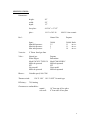
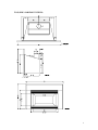
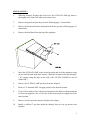
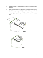
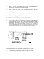
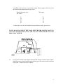
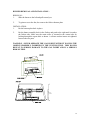
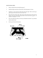
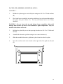
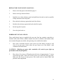
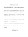
ULTRA FLAME
FIREPLACE GAS INSERT
INSTALLATION AND OPERATING INSTRUCTIONS
FOR YOUR SAFETY
DO NOT STORE OR USE GASOLINE OR OTHER FLAMMABLE VAPORS AND
LIQUIDS IN THE VICINITY OF THIS OR ANY OTHER APPLIANCE.
FOR YOUR SAFETY
IF YOU SMELL GAS :
1. OPEN WINDOWS
2. TURN OFF MAIN GAS SUPPLY
3. DON’T TOUCH ELECTRICAL SWITCHES
4. EXTINGUISH ANY OPEN FLAME
5. IMMEDIATELY CALL YOUR GAS SUPPLIER
Manufactured by :
Tested by :
DROLET STOVES & FIREPLACES INC.
1700, Leon-Harmel
Quebec, Qc (Canada)
G1N 4R9
WARNOCK HERSEY
Rev. 07/96 45028A
TABLE OF CONTENTS :
GENERAL INFORMATION :.............................................................................
2
WARNING :........................................................................................................
3
SPECIFICATIONS :............................................................................................
4
TOP, SIDE AND FRONT VIEWS :.........................................................
5
INSTALLATION :...............................................................................................
6 to 10
GLASS FRONT REMOVAL CLEANING AND INSTALLATION :........ 11
BURNER REMOVAL AND INSTALLATION :...................................... 12
LOG INSTALLATION :...........................................................................
13
FACE PLATE ASSEMBLY AND INSTALLATION :.............................. 14-15
REFRACTORY PANELS INSTALLATION :.......................................... 16
EMBERS KIT INSTALLATION :............................................................
16
OPERATING INSTRUCTIONS :.........................................................................
17
LIGHTING INSTRUCTIONS :................................................................. 17
SHUTDOWN INSTRUCTIONS :.............................................................. 17
FAN OPERATION :..................................................................................
17
MAINTENANCE INSTRUCTIONS :................................................................... 18
PILOT BURNER ADJUSTMENT :........................................................... 18
OPTIONAL PARTS :...........................................................................................
19
REPLACEMENT PARTS :...................................................................................
19
LIMITED 5 YEARS WARRANTY :..................................................................... 20
1
GENERAL INFORMATION :
The ULTRA FLAME is a high efficiency fireplace gas insert with an input rating of 30
000 Btu/h with natural gas and 26 000 Btu/h with propane. It features a millivolt valve
with a constant pilot. This lets you choose between a wall mounted switch, a wireless
remote control to turn on or off the main flame at will. This also means that your
ULTRA FLAME gas valve is not connected to any exterior electrical supply and that
your appliance will continue to heat your house in the event of a power failure.
For added efficiency, we included a 140 CFM blower with speed control and thermoswitch. Your fan will therefore turn itself on or off automatically, if you so desire.
The ULTRA FLAME should only installed in a existing masonry or prefab fireplaces.
The installation must be in accordance with local building codes or, if inexistant, with
current CAN/CGA B149.1 & B149.2 , ANSI Z 223.1 installation codes for gas appliance.
The gas insert must be electrically grounded in accordance with the current electrical
Codes.
Read these instructions and consult your local building authorities before installing this
appliance. Install the unit and its venting system only as described in these instructions.
KEEP THESE INSTRUCTIONS FOR FUTURE REFERENCE
This gas insert has been tested by WARNOCK HERSEY according to the CAN-CGA2.22M86 standard, and Z21.50, 50A, 50B American standard.
2
WARNING
* INSTALLATION SHOULD BE DONE BY A QUALIFIED INSTALLER.
* DO NOT BURN WOOD OR ANY OTHER MATERIAL IN THE GAS INSERT.
* HOT WHEN IN OPERATION. KEEP, FURNITURE, CLOTHING AND
FLAMMABLE MATERIAL AWAY FROM THE APPLIANCE.
* ADVISE ADULTS AND CHILDREN TO THE HAZARD OF HIGH SURFACE
TEMPERATURES AND THAT THEY SHOULD STAY AWAY TO AVOID BURNS
OR CLOTHING IGNITION.
* YOUNG CHILDREN SHOULD BE SUPERVISED WHEN THEY ARE IN THE
SAME ROOM AS THE APPLIANCE.
* THE APPLIANCE SHOULD BE INSPECTED BEFORE USE AND AT LEAST
ANNUALLY BY A QUALIFIED SERVICE PERSON. MORE FREQUENT
CLEANING MAY BE REQUIRED DUE TO EXCESSIVE LINT FROM CARPETING,
DUST, BEDDING MATERIAL, ETC.
* IT IS IMPERATIVE THAT THE CONTROL COMPARTMENTS, BURNERS AND
CIRCULATING AIR PASSAGEWAYS BE KEPT CLEAN.
* DO NOT MODIFY THIS APPLIANCE.
* THE LOUVER OPENINGS ON THE GAS INSERT FACE PLATE SHOULD
NEVER BE BLOCKED.
* PROVIDE ADEQUATE ACCESSIBILITY CLEARANCES FOR SERVICING AND
PROPER OPERATION.
3
SPECIFICATIONS :
Dimensions :
height :
width :
depth :
20”
28”
15”
face plate :
44 5/16” x 27 1/2”
glass :
14 1/2 x 30 5/16
Fuel :
Input :
Manifold pressure :
Min inlet pressure :
Max inlet pressure :
Vent size :
4” Diam. listed gas liner
Valve :
Natural gas
White Rogers
Model 36C03U TYPE 139
Millivolt operated
SIT
Nova model
Millivolt operated
Blower :
Variable speed, 140 CFM
Thermo-switch :
Efficiency :
1400° F clear ceramic
Natural Gas
Propane
30 000
3.5
5
7
26 000
11
11
14
Btu/h
in w.c.
in w.c.
in w.c.
Propane
Robertshaw
Model 7000 MVRLC
Millivolt operated
SIT
Nova model
Millivolt operated
120° F “ON” 110° F “OFF” bi-metal type
74% heating
Clearances to combustibles :
mantel :
side wall :
10” from top of face place
0” from side of face plate
4
TOP, SIDE AND FRONT VIEWS :
5
INSTALLATION :
1.
When the masonry fireplace that will receive the ULTRA FLAME gas insert is
thoroughly cold, remove all ashes and vacuum clean.
2.
Remove the glass front from the gas insert following page 11 instructions.
3.
Remove the burner and firebox bottom plate from the gas insert following page 12
instructions.
4.
Remove the draft hood from the top of the appliance.
5.
Move the ULTRA FLAME to the desired position and level the appliance using
the two bolts located in the back corners. Mark the location for the gas inlet pipe.
( We suggest using the hole in the back of the ULTRA FLAME for ease of
connection. )
6.
Remove the ULTRA FLAME gas insert from the fireplace.
7.
Route a 3/8” minimum NPT iron pipe gas line to the desired location.
8.
If you wish to make a direct electrical connection to the blower without using the
six foot cord supplied, route a 120 volts, 60 Hz electrical power supply line to the
same location.
9.
Remove or block open the masonry fireplace flue damper.
10.
Install a certified 4” gas liner inside the chimney from its very top down to the
fireplace.
6
11.
Secure the liner to the 4” connector on the top of the ULTRA FLAME with three
metal screws.
12.
Push the ULTRA FLAME back in the fireplace while pulling the draft hood in
place. To do so, fix two ropes to the draft hood sliders. Make sure the draft hood
front lip is squeezed under the steel angle to prevent any motion. The probe tube
must go through the top of the appliance tube accessible by opening the top front
grill. When the hood is in its location, fix it with 2 screws in the prepunched
holes.
7
13.
Install a 1/8” NPT plugged tapping for test gauge connection immediately
upstream of the gas supply connection to the appliance.
14.
Install a shutoff valve to the gas line. Tighten securely using a pipe joint
compound.
15.
Install a 3/8” flex connector to connect the shutoff valve to the gas valve on the
fireplace. Tighten securely using a pipe joint compound.
16.
Check the gas line piping for leaks. Use a soap and water solution.
WARNING : DO NOT USE OPEN FLAME TO CHECK LEAKS.
17.
If you decided to make a direct connection to the fan step 8, remove the power
cord and connect the 120 V line. To do so, unscrew the speed control unit and pull
away from the junction box a few inches. Unscrew the two mar connectors
attached to the cord (P) and the cord ground. Remove the cord and route the
supply line through the same holes. Make the electrical connection with the same
wires the cord was attached to. Screw the ground wire to the junction box (G).
If you prefer to use the six foot cord supplied, just connect it to a 120 V outlet.
18.
If you want to turn the main burner ON and OFF using a wall switch :
8
- Install the wall switch in a convenient location. Route a proper sized wire from
the switch or the thermostat to the gas valve.
Distance between valve
and switch
8’
12’
20’
32’
50’
Wire gage
22
20
18
16
14
- Connect the wires in serial with the face plate flame switch ( green wires ).
NOTE : DO NOT CONNECT THE WALL SWITCH WIRE OR THE VALVE TO
120 VOLTS POWER SUPPLY LINE. THE VALVE IS OPERATED BY ITS OWN
MILLIVOLT SYSTEM.
19.
If you want to turn the main burner ON and OFF using a wireless remote control,
install the remote control module apart from the gas valve and as close to the front
as possible. Connect the wires as shown.
9
20.
Install the firebox bottom plate and burner following page 12 instructions.
21.
Install the 4 logs on the burner as shown on page 13.
22.
If so desired, install the embers kits as shown on page 16.
23.
Install the glass front following page 11 instructions.
24.
Install the face plate according to page 14 instructions.
25.
Install a cap on the liner.
26.
Install a flashing on top the chimney to seal around the liner and to prevent water
infiltration.
10
GLASS FRONT REMOVAL CLEANING AND INSTALLATION :
* To remove the glass front, unscrew the six screws holding it in place as shown.
CAUTION : Hold the glass while unscrewing to prevent it from falling.
* Clean the glass only with liquid cleaners or soaps and water, do not use abrasive
cleaners which could remove the coating on the glass.
WARNING : Do not clean when hot, turn off the fireplace at least 30 minutes
before removing the glass front.
* The glass used on your fireplace is a high temperature ceramic 5 mm thick with a
special coating for use with gaseous fuels. Do not replace it with any other material.
CAUTION : Do not operate your fireplace without a glass or with a broken
glass.
11
BURNER REMOVAL AND INSTALLATION :
REMOVAL :
1.
Slide the burner to the left and pull toward you.
2.
To gain access to the fan, also remove the firebox bottom plate.
INSTALLATION :
1.
Put the bottom plate back in place.
2.
Put the burner assembly back in the firebox and push to the right until it touches
the firebox side. Make sure the main orifice is inserted in the venturi tube by
looking through the square hole as shown. A silicone washer insures air tightness
between the two parts.
WARNING : NEVER OPERATE THE GAS INSERT WITHOUT HAVING THE
ORIFICE PROPERLY INSERTED EN THE VENTURI TUBE. THIS WOULD
RESULT IN SERIOUS DAMAGE TO THE GAS INSERT AND IS A SERIOUS
RISK OF FIRE.
12
LOG INSTALLATION :
1.
Remove the glass front as described on page 11.
2.
Install the longer log in back of the firebox with locating grooves on top.
3.
Install the 14” log in the front of the firebox and to the right. Make sure the log is
pushed against the metal retainer on the burner face.
4.
Place the front of the log with a hole in the second notch from the left in the log
holder at the front of the burner and position it back in the back log groove. It
should be touching the 14” LOG.
5.
Place the smallest log sideways on the top of both the back and 14” logs with the
bend toward the front.
6.
Put the glass front back in the place.
13
FACE PLATE ASSEMBLY AND INSTALLATION :
ASSEMBLY :
1.
Bolt the face plate top piece to the left piece using two #10-24 x 1/2 bolts and nuts
(B).
2.
Place both louver assemblies in position with their pivot rod inserted through the
face plate side pieces holes (C). The top and bottom louvers are clearly
identified.
WARNING : Do not invert the top and bottom louver assemblies, this would
damage them because top louvers can withstand to higher temperature. They are
marked with stickers at one end.
3.
Bolt the face plate left piece to the top using the other two #10-24 x 1/2 bolts and
nuts (B).
4.
Assemble the decorative gold trim using the two corner brackets (A).
5.
Slide the assembled decorative gold trim in place from above the face plate.
6.
Insert the switches in the slots located on the right side of the gold trim (E) and
(F).
14
INSTALLATIONS :
1.
Screw the air deflector on the unit as shown using three #10 x 1/2 metal screws.
2.
Bring the face plate in position on the gas insert taking care to slip the air
deflector between the top louver and the bottom of the top piece. Secure using
four #10 x 1/2 metal screws (D).
3.
Connect the slip on the terminals on the rocker switch making sure the wires are
in pairs by color. The green wires lead to the valve and the yellow to the fan.
WARNING : Do not connect two wires of different color on the same switch, this
would result in damage to the valve and possible harm to the operator.
15
REFRACTORY PANELS INSTALLATIONS :
1.
Remove the front glass as described on page 11.
2.
Remove the logs from the firebox.
3.
Install the two sides refractory panels and pull them forward as mush as possible
to help insertion of the back panel.
4.
Place the back refractory against the back of the firebox.
5.
Push the side refractory against the back to hold it in place.
6.
Put the logs back in place.
7.
Screw the glass back on.
EMBERS KIT INSTALLATIONS :
Three small plastic bags are supplied with your unit. One bag contains vermiculite to
simulate ashes in the firebox, another contains lava rocks to simulate coals and the other
one contains fibreglass mat which, when glowing red, resembles hot embers.
1.
Place some vermiculite and lava rock on the top of the burner, keeping it well
clear of any gas ports ( holes where the gas comes out of the burner ) and
combustion air intake holes.
CAUTIONS : Blocking gas ports with vermiculite will result in poor light up
performance and delayed ignition.
2.
Place four or five pieces of fibreglass mat with sizes of approximately 1” on top
of the front gas ports. Place two or three pieces over each of the back gas ports.
Make sure not to put to many pieces, this would result in altered flame and
possible carbon deposition.
16
OPERATING INSTRUCTIONS
LIGHTING INSTRUCTIONS :
1.
Open the bottom louvers of the face plate to reach the control.
2.
Turn the gas valve knob to the “OFF” position and wait 5 minutes.
Note : You have to depress the gas valve knob to turn from “PILOT” to “OFF” or from
“OFF” to “PILOT”.
3.
Turn the gas valve knob to “PILOT”.
4.
Depress and hold the knob while lighting the pilot by pressing the pilot igniter
button (RED button ). Keep the knob depressed for about 1 minute. Release the
knob. The pilot should continue to burn by itself, if not, repeat step 4.
Note : You may need to press the pilot igniter button more than one time to light the
pilot.
5.
Turn the gas valve knob to the “ON” position.
6.
Turn the face place mounted switch to the “ON” position. If you don’t have an
additional wall switch , the main burner will come on. Otherwise, turn the wall
switch to “ON” if you want the main burner to come on.
7.
The other knob controls the gas flow and the power of the appliance.
SHUTDOWN INSTRUCTIONS
Main burner only : Turn off the face plate switch ( or wall switch ).
To relight the main burner, turn the switch on ( or the wall switch )
Pilot and Main burners : Turn the gas valve to the “OFF” position. Depress the knob to
pass from the “PILOT” to “OFF” position.
FAN OPERATION :
To turn the air blower “ON” or “OFF”, activate the face plate switch connected to the
yellow wires. The fan will not start if the appliance is cold. Operate the gas insert for at
least 15 minutes to heat up the thermo-switch. The fan will also turn itself off about 20
minutes after extinction of the main flame.
Note: The speed control must also be on to allow fan to work.
17
MAINTENANCE INSTRUCTIONS :
TURN OFF THE GAS WITH THE SHUTDOWN VALVE AND THE ELECTRICAL
POWER BEFORE SERVICING THE APPLIANCE.
* The venting system and the gas insert should be inspected at least once a year.
* Remove the glass front and the logs clean them if necessary.
* The control compartment, air circulating passages, firebox, logs and burner should be
cleaned at least once a year by vacuuming or brushing.
* Check the pilot flame to see if it is adjusted properly. Re-adjust the pilot flame if
necessary ( as described below ) or clean the pilot orifice if re-adjustment is not
possible.
* Check the burner for flame lifting or for usual flame pattern. If necessary clean the
burner orifice.
* Keep the area and the free from combustible materials, gasoline and other flammable
vapors and liquids.
PILOT BURNER ADJUSTMENT :
The flame from the pilot should cover 3/8” to 1/2” of the power generator. If not, you
need to do the following adjustment.
1.
Remove the pilot adjustment cap on the gas valve. Depending on the valve model,
the pilot adjustment screw could be indicated differently.
2.
Adjust the pilot key to provide a properly sized flame.
3.
Replace the pilot adjustment cap on the gas valve.
18
OPTIONAL PARTS
ITEM DESCRIPTION
Part No
QTY
Face plate, silver gray enamel
Face plate, black enamel
Face plate, gold
Face plate, charcoal painted
Face plate, black painted
Wall switch
Remote control
Decorative refractory kit
E5422
E5420
E5415
E5416
E5418
E5978
E5568
E5988
1
1
1
1
1
1
1
1
ITEM DESCRIPTION
Part No
QTY
Log kit
Back log only
Front log only
Top log, small only
Top log, holed only
Burner assembly
Burner orifice (natural gas or propane)
Pilot assembly (natural gas or propane)
Thermopile
Piezo igniter
Gas valve (natural gas or propane)
Glass
Variable speed control
1
Blower
Thermo-switch
Rocker switch
2232
2232 BACK
2232 FRONT
2232 SMALL
2232 HOLED
7950
49060
49092
49091
49050
49090
7916
44080-44085
1
1
1
1
1
1
1
1
1
1
1
1
44070
44040
44090
1
1
2
REPLACEMENT PARTS
19
____________________________
LIMITED 5 YEARS WARRANTY
____________________________
DROLET STOVES AND FIREPLACES INC. hereby warrants the quality of its fireplace
gas insert against manufacturing defects. The product shall be delivered to the buyer in
good condition and the latter should inform the vendor immediately of any defect in the
product delivered.
During the first year of the limited warranty, DROLET STOVES AND FIREPLACES
INC. will provide free replacement parts for the fireplace gas insert except for the glass
assembly. DROLET STOVES AND FIREPLACES INC. will cover labor related costs
deemed reasonable by the company. All other costs related to dismantling the structure,
decoration, venting system, etc. are the responsibilities of the fireplace gas insert owner.
During the second to the fifth year of the limited warranty, DROLET STOVES AND
FIREPLACES INC. will replace defective parts free of charge except the VALVE,
IGNITION CONTROL, BURNER CONTROL.
DROLET STOVES AND
FIREPLACES INC. will not compensate for labor costs related to parts replacement.
The warranty is conditional upon proper installation in accordance with manufacturer’s
instructions.
All repairs must be approved by an official representative of the company before being
undertaken.
The delivery costs of all replacement parts provided by DROLET STOVES AND
FIREPLACES INC. are the responsibilities of the client.
This warranty may not be transferred to a second person and becomes effective on the
date the product is purchased.
The warranty may not be extended in any way by your representatives, dealers or any
other intervening party.
No other claim of any nature whatsoever shall be considered by the vendor or
manufacturer.
DROLET STOVES AND FIREPLACES INC.
1700 Leon-Harmel
Quebec (Quebec) Canada
G1N 4R9
20