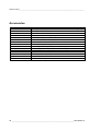
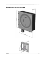
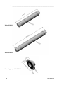
1
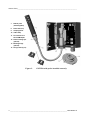
USER'S GUIDE
®
Vaisala CARBOCAP Carbon Dioxide
Transmitter Series
GMT220
M010022EN-C
PUBLISHED BY
Vaisala Oyj
P.O. Box 26
FIN-00421 Helsinki
Finland
Phone (int.): +358 9 8949 1
Fax:
+358 9 8949 2227
Visit our Internet pages at http://www.vaisala.com/
© Vaisala 2006
No part of this manual may be reproduced in any form or by any means, electronic or
mechanical (including photocopying), nor may its contents be communicated to a third
party without prior written permission of the copyright holder.
The contents are subject to change without prior notice.
Please observe that this manual does not create any legally binding obligations for
Vaisala towards the customer or end user. All legally binding commitments and
agreements are included exclusively in the applicable supply contract or Conditions of
Sale.
CHAPTER 1_______________________________________________________ GENERAL INFORMATION
Table of contents
CHAPTER 1
GENERAL INFORMATION ............................................................................2
Safety .........................................................................................2
Warranty ....................................................................................2
CHAPTER 2
PRODUCT DESCRIPTION.............................................................................3
Parts ...........................................................................................3
Led light indicators and optional display...............................5
CHAPTER 3
MOUNTING.....................................................................................................6
Wall mounting ...........................................................................6
Duct or channel mounting .......................................................7
CHAPTER 4
ELECTRICAL CONNECTIONS......................................................................8
Power supply requirements ....................................................9
Connection to a 24 VAC supply ..............................................9
Relays ......................................................................................10
CHAPTER 5
MAINTENANCE............................................................................................11
Replacing the probe ...............................................................11
Transmitter with integrated probe (wall model) ..............11
Transmitter with remote probe .......................................11
Calibration ...............................................................................12
Comparison with the calibrated probe............................12
On-site checking and adjusting by using a reference gas
and GM70 hand-held meter ...........................................12
Calibrator GMK220.........................................................12
Error messages.......................................................................13
Transmitters with a display.............................................13
Transmitters without a display........................................14
CHAPTER 6
SERIAL COMMANDS ..................................................................................15
Setting relay trigger points ....................................................16
Pressure compensation .........................................................16
Temperature setting ...............................................................17
CHAPTER 7
TECHNICAL DATA.......................................................................................18
Technical specifications ........................................................18
Operating conditions ......................................................18
Mechanics ......................................................................19
Electromagnetic compatibility.........................................19
Accessories ....................................................................20
Dimensions in mm (inches) ...................................................21
VAISALA __________________________________________________________________________ 1
USER'S GUIDE_______________________________________________________________________
CHAPTER 1
GENERAL INFORMATION
Safety
Throughout the manual, important safety considerations are
highlighted as follows:
WARNING
Warning denotes a serious hazard. It calls attention to a procedure,
practice, condition or the like, which, if not correctly performed or
adhered to, could result in injury to or death of personnel.
CAUTION
Caution denotes a hazard. It calls attention to a procedure, practice,
condition or the like, which, if not correctly performed or adhered to,
could result in damage to or destruction of part or all of the product.
NOTE
Note highlights important information. It calls attention to an
essential procedure, practice, condition or the like.
Warranty
Vaisala issues a guarantee for the material and workmanship of this
product under normal operating conditions for one (1) year from the
date of delivery. Exceptional operating conditions, damage due to
careless handling and misapplication will void the guarantee.
2 ____________________________________________________________________ M010022EN-C
CHAPTER 2_______________________________________________________ PRODUCT DESCRIPTION
CHAPTER 2
PRODUCT DESCRIPTION
Vaisala’s GMT220 transmitters are versatile instruments for
measuring CO2 in industrial applications. The CARBOCAP® sensor is
silicon based and its operation is based on the NDIR Single-Beam
Dual-Wavelength principle.
Parts
The GMT220 transmitter is shown in Figures 1 and 2.
1.
Transmitter cover
2.
Transmitter housing
3.
Integrated probe
(interchangeable)
4.
Printed protective
film
5.
Tightening screw
6.
Cable gland
(I.D. 6 mm)
Figure 1.
GMT220 with probe integrated into the transmitter
housing e.g. wall model transmitter.
VAISALA __________________________________________________________________________ 3
USER'S GUIDE_______________________________________________________________________
7.
Remote probe
(interchangeable)
8.
Probe cable (2 m)
9.
Clamping sleeve
10. Cable clamp
11. Pin connector for a
serial COM adapter
12. Probe mounting clips
(optional)
13. Mounting flange
(optional)
14. Fixing screws (4 pcs)
Figure 2.
GMT220 with probe installed remotely.
4 ____________________________________________________________________ M010022EN-C
CHAPTER 2_______________________________________________________ PRODUCT DESCRIPTION
Led light indicators and optional display
The GMT220 series transmitter has as a standard three LED light
indicators on the cover plate: OPERATION, LEVEL 1 and LEVEL 2 (see
Figure 3).
• The green OPERATION LED is lit as the power is connected.
• The red LEVEL LEDS are lit if the relay setting is reached e.g CO2
concentration is over predefined limit. If the relays are not in use,
the LEVEL LEDs indicating CO2 concentration are dark.
The transmitter is also available with an optional back lit LCD
display, which outputs the CO2 volume concentration in unit of
percentage or ppm depending on the measurement range of the probe.
Blinking led lights and Er-codes in the display indicate operation
errors (see Chapter 5, Error messages).
Figure 3.
LED
light indicators and optional display.
VAISALA __________________________________________________________________________ 5
USER'S GUIDE_______________________________________________________________________
CHAPTER 3
MOUNTING
Wall mounting
Mount the wall model transmitter or the remote probe into a place
representing the environment to be measured.
1.
Attach the mounting
plate to the wall with
screws.
2.
Press down the
transmitter so that it
slides along the rails
of the mounting plate.
Figure 4.
Mounting the transmitter
6 ____________________________________________________________________ M010022EN-C
CHAPTER 3_________________________________________________________________ MOUNTING
Duct or channel mounting
When the probe is installed in a duct or channel, it is recommended to
use the optional mounting flange (GM45156SP).
1. Drill a hole with minimum diameter of 22 mm in the wall.
2. Attach the flange onto the duct with four screws so that the gasket
ring seals the attachment.
3. Place the probe through the flange so deep that the perforated
head is completely in the duct (see Figure 5).
Gasket ring
Figure 5.
NOTE
Mounting the probe in a duct or channel.
If the air pressure in the duct is clearly lower than in surroundings, an
additional sealing may be necessary. This is to avoid possible
measurement errors due to leakages through the joint.
VAISALA __________________________________________________________________________ 7
USER'S GUIDE_______________________________________________________________________
CHAPTER 4
ELECTRICAL CONNECTIONS
1. Connect the nominal 24 V supply terminals (+) and (-) on the
motherboard (right-hand side, see Figure 6).
2. Connect the analogue output (see Figure 6) as follows:
Terminal 0:
Terminal V:
Terminal mA:
the common wire (-)
voltage output signal (+)
current output signal (+)
If the current output is chosen, select the output range by using the
current output jumper 4mA (see Figure 6). If the range of 4...20mA is
chosen, connect the jumper (default). If the range of 0...20 mA is
chosen, disconnect the jumper.
CAUTION Connecting power leads to the output terminals can seriously damage
the product.
Current output
jumper (4 mA)
Relay jumpers
(L1 and L2)
LonWorks
terminals
Relay 2
terminals
Relay 1
terminals
Serial port
4 mA
L2
L1
A
B
C
D
(~) +
24 V (~) -
RELAY 2
OUT
RELAY 1
0
V
mA
Power supply
terminals
Output terminals
WWW.VAISALA.COM
JVU
Figure 6. Electrical connections and jumpers.
8 ____________________________________________________________________ M010022EN-C
CHAPTER 4 _____________________________________________________ ELECTRICAL CONNECTIONS
Power supply requirements
The GMT220 series transmitters are designed to operate with a
nominal 24 VAC/DC supply. The power supply should maintain the
voltage for all load conditions and all mains voltages. The power input
includes a halfwave rectifier. To avoid current peaks, it is
recommended to use a DC supply.
Connection to a 24 VAC supply
The GMT220 series transmitters can be connected to a 24 VAC
supply without an external rectifier. However, when more than one
transmitter is connected to one 24 VAC transformer, a common loop
is formed and risk of a short-circuit increases. To avoid this, always
use separate floating supply for each transmitter (see figure 7 A).
CAUTION
If several transmitters have to share one transformer, the phase (∼)
must always be connected to (+) connector (24 V) in each transmitter
(see figure 7 B).
A) Connection of separate AC supplies to the transmitters (recommended connection).
GMT220
(∼)
24VAC
Supply
voltage
OUT
GND
Signal
output
GMT220
(∼)
24VAC
24V
CONTROLLER
Supply
voltage
24V
OUT
GND
Signal
output
B) Connection of one AC supply to the transmitters.
(∼)
24VAC
GMT220
Supply
voltage
24V
OUT
GND
CONTROLLER
Signal
output
GMT220
Supply
voltage
24V
OUT
GND
SHARED
COMMON
LINE
Signal
output
Figure 7. AC Connections.
VAISALA __________________________________________________________________________ 9
USER'S GUIDE_______________________________________________________________________
Relays
The relay output wiring is done at the left-hand side terminals on the
motherboard (see Figure 6). When the relay trigger point is exceeded,
the relay switches ON. This function can be inversed by disconnecting
the corresponding relay jumper (L1 or L2).
The relay trigger points have been set at factory as defined in the order
form. The points can also be changed with a PC and the optional serial
COM adapter 19040GM. For more detailed information see page 15.
10 ___________________________________________________________________ M010022EN-C
CHAPTER 5______________________________________________________________ MAINTENANCE
CHAPTER 5
MAINTENANCE
Replacing the probe
Transmitter with integrated probe (wall model)
1. Open the cover
2. Loosen the tightening screw on the transmitter body (see page 3).
3. Pull out the probe and install a new probe. Tighten the screw and
close the cover.
Transmitter with remote probe
1. Loosen the clamping sleeve, pull the probe out (see page 3).
2. Install a spare probe and tighten the clamping sleeve.
All the calibration electronics are in the probe. The new probe is
automatically identified by the control electronics of the transmitter.
NOTE
Disconnection of the probe causes an error and switches the relays
OFF.
VAISALA _________________________________________________________________________ 11
USER'S GUIDE_______________________________________________________________________
Calibration
Comparison with the calibrated probe
It is recommended to check the calibration of the GMT220 every
second year. A simple field calibration checking can be performed by
using a calibrated reference probe. During the checking procedure,
please avoid exhaling towards the probe as this alters the CO2
concentration.
1. Check the current transmitter reading.
2. Replace the probe with the reference.
3. Let the transmitter stabilize for a few minutes. The measured CO2
concentration near by the transmitter may have increased due to
breathing.
4. Compare the readings measured with the original and the
reference probe.
The difference between the readings should be less than 5 % of the
full scale reading of the GMT220. If there is need for an adjustment of
the probe, please contact Vaisala SSD Service or Vaisala's
representative (see page 14).
On-site checking and adjusting by using a
reference gas and GM70 hand-held meter
A probe to be checked can be flushed in a reference gas by using a
field check adapter (optional part, 26150GM). The procedure requires
pressurized gas bottle giving a flow rate of 0.4...1.0 l/min through the
adapter chamber. If an adjustment is needed, it can be carried out by a
user with a Vaisala's hand-held carbon dioxide meter GM70. Probes
can be sent also to Vaisala SSD Service Centers (see page 14) to be
calibrated.
Calibrator GMK220
The Vaisala GMK220 calibrator is intended for spot checking and
two-point calibration of the GMT220-series probes. The calibration
parameters are stored to the nonvolatile memory of the probes.
Contact Vaisala's representative to get more information about the
GMK220.
12 ___________________________________________________________________ M010022EN-C
CHAPTER 5______________________________________________________________ MAINTENANCE
Error messages
Transmitters with a display
The following error messages Er 01... Er 13 appears on the display as
an operation error occurs in the transmitter:
Error code
Type of error
Er 01
Main board memory problem
Er 02
Main board memory problem
Er 03
Main board memory problem
Er 04
Probe contact failure
Er 05
Probe memory failure
Er 06
Probe memory failure
Er 08
Incompatible probe
Er 10
IR-source failure
Er 11
IR-source failure
Er 12
Sensor failure
Er 13
Signal error
In all the error cases, check first that the probe is connected properly
then reset the transmitter by disconnecting it. In case of constant error,
please contact Vaisala SSD Service or local Vaisala representative
(see page 14).
NOTE
Disconnection of the probe and fatal operation errors switch the relay
OFF.
VAISALA _________________________________________________________________________ 13
USER'S GUIDE_______________________________________________________________________
Transmitters without a display
The transmitter without a display indicates problems by blinking the
three LED lights on the cover plate: OPERATION, LEVEL 1 and LEVEL 2
(see Figure 3) as follows:
• the green OPERATION LED is blinking when a non-critical error
occurs (no effect on relays).
• the red LEVEL 1 and LEVEL 2 LEDs are blinking when a fatal error
occurs (switches the relays OFF). Note ! The red LEVEL LED is
continously lit when the predefined CO2 concentration is
exceeded.
In case of non-critical or fatal errors, check first that the probe is connected
properly then reset the transmitter by disconnecting it. In case this does not
help, please contact Vaisala SSD Service or local Vaisala representative (see
Table 1).
Table 1. Vaisala SSD Service Centres.
NORTH AMERICAN SERVICE CENTER
Vaisala Inc., 100 Commerce Way, Woburn, MA 01801-1068, USA.
Phone: +1 781 933 4500, Fax +1 781 933 8029
Email: [email protected]
EUROPEAN SERVICE CENTER
Vaisala SSD Service, Vanha Nurmijärventie 21 FIN-01670 Vantaa, FINLAND.
Phone: +358 9 8949 2758, Fax +358 9 8949 2295
E-mail: [email protected]
ASIAN SERVICE CENTER
Vaisala KK, 42 Kagurazaka 6-Chome, Shinjuku-Ku, Tokyo 162-0825, JAPAN.
Phone: +81 3 3266 9611, Fax +81 3 3266 9610
E-mail: [email protected]
www.vaisala.com
14 ___________________________________________________________________ M010022EN-C
CHAPTER 6__________________________________________________________ SERIAL COMMANDS
CHAPTER 6
SERIAL COMMANDS
The GMT220 is linked to PC via a serial cable equipped with a COM
adapter (optional part 19040GM, can be ordered from Vaisala).
1. Connect the serial cable to your PC's serial port and transmitter's
serial port located in the motherboard, see figure below.
4 mA
L2
L1
A
B
C
D
24 V
(~) +
(~) -
OUT
0
V
mA
RELAY 2
RELAY 1
Serial
port
WWW.VAISALA.COM
Cable direction JVU
2. Set the serial settings as in the following table.
Table 2.
Baud rate
Parity
Data bits
Stop bits
Flow control
NOTE
Serial interface settings
9600
none
8
1
Xon/Xoff (none)
Remember to save the settings after each command.
VAISALA _________________________________________________________________________ 15
USER'S GUIDE_______________________________________________________________________
Setting relay trigger points
The relays of the transmitter turn ON/OFF when the CO2 content
reaches the predefined trigger point. There are two trigger points for
both relays. The higher limit activates the relay and the lower
deactivates it. The two limits are used to prevent the relay switching
back and forth when the measured value is very close to set point.
MF_Rx_HIGH yyy<cr>
where:
x = 1 or 2 (number of the relay)
yyy = trigger point (CO2 content in ppm)
Example of setting the higher trigger limit of the relay 1:
>MF_R1_HIGH 1200
MF_R1_HIGH=1200.0000
>
Save the settings:
MAIN_SAVE F<cr>
Give the lower trigger limit:
MF_Rx_LOW yyy<cr>
where:
x= 1 or 2 (number of the relay)
yyy = trigger point (CO2 content in ppm)
Example of setting the lower trigger limit of the relay 1:
>MF_R1_Low 900
MF_R1_LOW=900.000000
>
Save the settings:
MAIN_SAVE F<cr>
Pressure compensation
For achieving the most accurate measurements in high altitudes where
the barometric pressure is lower than in the sea level, the actual
pressure value can be set to the GMT220's software. The factory
16 ___________________________________________________________________ M010022EN-C
CHAPTER 6__________________________________________________________ SERIAL COMMANDS
setting is 1013 hPa. The ambient pressure value can be set by using
the following command:
MF_PRESSURE xxxx<cr>
where:
xxxx = pressure in hPa
Example of setting desired pressure:
>MF_PRESSURE 900
MF_PRESSURE=900
>
Save the settings:
MAIN_SAVE F<cr>
Altitude/Atmospheric pressure table
Altitude m (ft)
0 (sea level)
500 m (1640 ft)
1000 m (3281 ft)
1500 m (4921 ft)
2000 m (6562 ft)
2500 m (8202 ft)
3000 m (9843 ft)
Atmospheric pressure
(hPa)
1013
954
899
845
795
747
701
Atmospheric pressure
(psi)
14.69
13.84
13.04
12.26
11.53
10.83
10.17
Temperature setting
The ambient temperature value can be set by using the following
command:
MF_TEMP xxx<cr>
where: xxx = ambient temperature (°C) x 10.
Example of setting desired temperature (25 °C):
>MF_TEMP 250
MF_TEMP=250
>
Save the settings:
MAIN_SAVE F<cr>
VAISALA _________________________________________________________________________ 17
USER'S GUIDE_______________________________________________________________________
CHAPTER 7
TECHNICAL DATA
Technical specifications
Measuring range
GMT221
0...2% CO2, 0...3% CO2,
0...5% CO2, 0...10% CO2 ,
0...20% CO2
GMT222
0...2000 ppm, 0...3000 ppm,
0...5000 ppm, 0...7000 ppm,
0...10 000 ppm
Accuracy at 25°C against certified factory references
GMT221
<±[0.02% CO2 + 2% of reading]
GMT222
<±[20 ppm CO2 + 2% of reading]
(including repeatability and calibration uncertainty)
Non-linearity
<±0.5 %FS
Temperature dependence
(typically)
-0.1 %FS / °C (When temperature
rises, the output decreases, default
25 °C (77 °F))
Pressure dependence (typically)
+0.15 % of reading/hPa (When
pressure rises, the output increases,
default 1013 hPa (1 atm))
Long-term stability
Response time (63%)
<±5 %FS / 2 years
20 seconds (GMT221)
30 seconds (GMT222)
Operating conditions
Operating temperature range
Humidity range
General
Analog outputs
Resolution of analog outputs
-20…+60 °C
0 - 100 %RH (non-condensing)
0 - 20 mA or 4 - 20 mA and
0 - 10 V
0.03 %FS
18 ___________________________________________________________________ M010022EN-C
CHAPTER 7____________________________________________________________ TECHNICAL DATA
Recommended external load:
current output
voltage output
Relay contact ratings
Power supply
Power consumption
Warm-up time
Storage temperature range
max. 400 Ω
min. 1 kΩ
max. 30 VAC / 60 VDC, 0.5 A
nominal 24 VAC/DC
<4W
< 15 minutes
-30...+70°C
Mechanics
Housing material
transmitter body
probe
Housing classification
Weight
GMT221:
GMT222
ABS plastic
PC plastic
IP65/NEMA4
max. 280 g
max. 300 g
Electromagnetic compatibility
The GMT221 and GMT222 transmitters comply with the following
standards:
EN 61326-1:1997 + Am1:1998, Electrical equipment for
measurement, control and laboratory use - EMC requirements Generic environment.
[CISPR16/22 Class B, EN/IEC 61000-4-2, EN/IEC 61000-4-3,
EN/IEC 61000-4-4, EN/IEC 61000-4-5, EN/IEC 61000-4-6]
VAISALA _________________________________________________________________________ 19
USER'S GUIDE_______________________________________________________________________
Accessories
Order code
GMP221, GMP222
25378GMSP
25879GMSP
25245GMSP
26150GM
GM45168SP
GM45237SP
GM45156SP
25665GMSP
210848GMSP
19040GM
GML220
26204GM
GM70
GMK220
Description
Spare probe (use the order form to define measurement range etc.)
Spare filter for GMP221
Spare filter for GMP222
Clips (2 pcs) for attaching the probe
Field check adapter
Protective sleeve for the GMP221
Protective sleeve for the GMP222
Mounting flange for the probe
2 meters probe cable (includes a cable clamp)
10 meters probe cable (includes a cable clamp)
Serial COM adapter
LonWorks® module*
XIF-external interface file for LonWorks®module
Hand-held carbon dioxide meter
Calibrator for the probes
20 ___________________________________________________________________ M010022EN-C
CHAPTER 7____________________________________________________________ TECHNICAL DATA
Dimensions in mm (inches)
VAISALA _________________________________________________________________________ 21
USER'S GUIDE_______________________________________________________________________
Probe GMP221
Probe GMP222
Mounting flange GM45156SP
22 ___________________________________________________________________ M010022EN-C
CHAPTER 7____________________________________________________________ TECHNICAL DATA
VAISALA _________________________________________________________________________ 23
www.vaisala.com