1
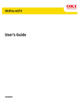
BW651 final.qxd
10/18/2005
10:58 AM
Page 1
REMOTE AUTO START
Optional Keyless Entry Instructions Included
SYSTEM MANUAL
STANDARD FEATURES
Some of the system’s standard features include:
• 4-button remote transmitter
• Extended range receiver w/built-in LED status
indicator & valet switch
• Flashing parking lights
• Auto cold Start feature
• Stop & go feature
• Programmable engine run-time
• Hood & brake pedal safety inputs
SYSTEM OPERATION
OPTIONAL FEATURES
This system has optional features that may
require additional parts and/or labor. Please
contact your dealer for more details.
• Remote keyless entry (door lock/unlock)
• Trunk/hatch release
Note: Some features may not be appropriate
for certain vehicles.
COMFORT CLOSURE
The optional Comfort Closure feature activates
the lock output as long as button 1 is held. Using
this feature will roll-up the windows and close
the sunroof on some late model vehicles.
To activate the Comfort Closure feature:
1. Press and release transmitter button 1 to
lock the doors.
2. Immediately press and hold button 1 again
until the windows and sunroof are closed.
• The LED will flash once.
• The parking lights will flash once.
• The doors will lock.*
*Optional Feature
DOOR LOCKING
To lock the system press transmitter button 1:
• The parking lights will flash once.
• The horn will honk once.*
• The doors will lock.*
• The LED will begin flashing after 3
seconds.
• The Starter Defeat feature will activate.*
*Optional Feature
REMOTE TRANSMITTER BUTTONS
Button 1
Button 2
Button 3
Button 4
DOOR UNLOCKING
To unlock the system press transmitter button 2.
• The parking lights will flash twice.
• The horn will honk twice.*
• The doors will unlock.*
• The LED will stop flashing.
• The Starter Defeat will deactivate.*
* Optional Feature.
Transmitter Icons
NOTE: Transmitter cosmetics may differ, but
button functions remain the same as described:
Button 1 locks the doors* and also activates
the Panic Mode* when held for 4 seconds.
Button 2 unlocks the doors*.
Button 3 controls the Remote Start feature.
Button 4 activates the Car Finder feature.
1
BW651 final.qxd
10/18/2005
10:58 AM
Page 2
seconds. NOTE: the Trunk Release feature may
be programmed to activate with button 4
instead. See your dealer for more details.
SILENT LOCKING/UNLOCKING
If the optional Horn Honk feature is installed,
pressing transmitter buttons 1&2 together
provides one-time silent operation. The system
locks or unlocks the doors without horn
confirmation.
CAR LOCATOR FEATURE
To activate the system’s car locator feature
press and hold button 4 for three seconds. The
parking lights will flash and the horn will honk
(optional) 5 times.
IGNITION CONTROLLED LOCKS
The ignition controlled locks feature
automatically locks the doors after turning on
the ignition, and unlocks when the ignition key
is turned off. This feature may also be
programmed for ignition lock without ignition
unlock, and off (no ignition control).
REMOTE START FEATURES
Important: Only start the vehicle in a well
ventilated area. Do not use in a closed garage
or indoors. Be sure to familiarize yourself with
all features prior to using the remote start.
VALET MODE
When the system is placed into the Valet Mode
the remote start feature will be disabled.
However, the optional keyless entry and trunk
release features will still function if installed.
To enter mode:
1. Be sure the system is in unlock mode.
2. Turn ignition on.
3. Press and hold the valet switch for 5
seconds.
• The LED will turn on solid 5 seconds
after turning ignition off.
• The horn will honk 5 times.*
4. Turn ignition off.
To exit valet mode:
1. Be sure the system is in unlock mode.
2. Turn ignition on.
3. Press and hold the valet switch for 5
seconds.
• The LED will turn off.
• The horn will honk twice.*
4. Turn ignition off.
REMOTE STARTING THE VEHICLE
To remote start the vehicle press button 3.
• The parking lights will flash 4 times then
remain on.
• The system will attempt to start.
• Once the car has started, the heater or air
conditioner will turn on and run for the
pre-programmed time. If the engine fails to
start on the first attempt, it will attempt to
start 2 more times. If the vehicle fails to
start after a total of 3 times the system
will shut down.
To drive the vehicle after Remote Starting:
Unlock the door by pressing button 2 on the
remote transmitter. Enter vehicle, turn
ignition key on position and press brake pedal
NOTE: Do not turn the key to the start position
as the engine is already running.
If brake pedal is pressed prior to turning on
ignition, engine will turn off.
REMOTE ENGINE SHUTDOWN
If the vehicle has been remotely started and
you desire to turn the vehicle off, simply press
and hold button 3 for 3 seconds.
OPTIONAL TRUNK RELEASE
The activate the system’s auxiliary feature (or
trunk release) press button 2 for three
2
BW651 final.qxd
10/18/2005
10:58 AM
Page 3
To turn Auto Cold Start on:
1. Press and hold buttons 1 & 3 together for
3 seconds.
• The parking lights will turn on for 10
seconds to confirm activation.
2. Press the button corresponding to the
desired start cycle interval:
Button 2 = start every 2 hours
Button 3 = start every 3 hours
Button 4 = start every 4 hours
• The parking lights will flash a number
of times equal to the chosen interval.
STOP AND GO
The Stop and Go feature allows the vehicle to
remain running without use of the ignition key
during short stops.
To activate the Stop and Go feature:
1. Make sure the engine is running.
2. Press button 3.
3. Turn ignition off.
• The doors will unlock.
• The parking lights will turn on.
• The engine will remain running.
4. Exit the vehicle and lock the doors using
transmitter button 1.
To resume driver control:
1. Unlock the doors by pressing transmitter
button 2.
2. Turn on the ignition.
• The vehicle resumes driver control,
when the brake pedal is pressed.
Disengaging the Auto Cold Start feature:
Any of the following actions will cancel the
Auto Cold Start feature:
Press and hold buttons 1 & 3 together for 3
seconds.
• The parking lights will flash twice and
the horn will honk twice (optional) to
confirm deactivation.
- or Press the brake pedal.
- or Turn ignition on.
AUTO COLD START
This feature allows the system to start and run
the vehicle every 2, 3, or 4 hours (user
selectable) for up to 12 starts. This allows the
engine to remain at an operational temperature
in extremely cold weather. Auto Cold Start
interval timing must be chosen during
installation.
Engaging the Auto Cold Start feature:
SAFETY FEATURES
The System will not start the vehicle if the
brake pedal is pressed, if the hood is open, or if
the system is in Valet mode.Also, if the brake is
pressed or the hood is opened while remote
running, the remote start will shut down.
LED AND PARKING LIGHT DIAGNOSTIC INDICATIONS
Parking Light
3 Slow Flashes
5 Slow Flashes
5 Flashes
5 Flashes
7 Flashes
LED Indication
On Solid
No Flashes
5 Flashes
5 Flashes
7 Flashes
Problem
System in Valet Mode
Key is on during remote start attempt
Open hood warning (before start)
System shut down using brake pedal (when running)
Tachometer lock out (see dealer)
3
BW651 final.qxd
10/18/2005
10:58 AM
Page 4
REMOTE AUTO START
Optional Keyless Entry Instructions Included
INSTALLATION INSTRUCTIONS
BEFORE INSTALLING THIS PRODUCT PLEASE READ
THE INSTALLATION DIRECTIONS THOROUGHLY!!
BEFORE YOU BEGIN
This system is compatible with electronic
fuel injected engines only! Not intended for
use with carbureted engines.
• This product must be installed by qualified
personnel according to these instructions and
and observing all safety features.
• Check to see if the vehicle is equipped with
any type of factory security system.
• Check to see if there is a pin switch for the
hood, if not one must be installed.
• Verify that the vehicle starts and idles
properly before beginning the installation.
• Always use a multi-meter to verify wiring.
• Before mounting the product, verify with the
customer the desired location for the window
mount receiver.
the remote transmitter is used to lock the
doors or when the remote start shuts down.
See Programmable Features
• RED/WHITE WIRE - Auxiliary / trunk release
output (-) 250mA. Connect to a relay for an
optional feature such as trunk release. The
RED/WHITE wire can instead be programmed
for use as a negative parking light output if
needed, and the WHITE positive parking light
output then becomes a positive trunk release
output. See Programmable Features
• BROWN WIRE - Factory Alarm Disarm
output (-) 250mA. Connect to the wire that
requires a ground pulse to disarm the factory
alarm. The BROWN wire provides a ground
pulse when the remote transmitter is used to
unlock the doors or start the vehicle.
• ORANGE WIRE - Ground when running /
Anti-grind output (-) 250mA. The ORANGE
wire can be also programmed for use as a
Starter Defeat output with Anti-grind or as a
passive Starter Defeat output that activates 30
seconds after the ignition is turned off.
Ground when running (default): Provides a
ground when the remote start is activated and
is normally used to activate an optional factory
security bypass module, a relay for anti-grind, a
3rd ignition relay, etc.
Starter defeat w/ anti-grind: Provides a ground
when the remote start is activated and when
button 1 is used to lock the doors.
Starter defeat w/ passive operation: Provides a
ground to activate a starter defeat relay 30
MOUNTING SYSTEM COMPONENTS
Mount the start module under the dash where
it will be away from moving parts such as brake
pedals, etc. Mount the receiver to the inside of
the windshield using the supplied double-sided
tape. Make sure the chosen location does not
obscure the driver’s view.
MODULE WIRING
12-Pin Main Harness
• YELLOW WIRE - Factory Alarm Arm output
(-) 250mA. Connect to the wire that requires a
ground pulse to arm the factory alarm. The
YELLOW wire provides a ground pulse when
4
BW651 final.qxd
10/18/2005
10:58 AM
Page 5
to it. Negative glow plug wire systems will show
+12V when the the glow plug (wait-to-start)
light is on, then show ground when the light
turns off. Positive glow plug wire systems will
show ground when the wait-to-start light is on.
The BLUE wire is programmable for the system
polarity and should be connected directly to the
glow plug wire. See Programmable Features
seconds after the ignition is turned off and
anytime button 1 is used to lock the doors.
• WHITE/BLUE WIRE - Horn output (-)
250mA. Connect to an optional relay to
activate the vehicle’s horn. The horn output is
programmable for pulse duration and to set
which functions will trigger the horn pulses.
• BLACK/WHITE WIRE - Not used.
• VIOLET WIRE - Not used.
• WHITE WIRE - Parking Light output (+) 10A
relay. Connect to the vehicle’s parking light
wire. If the vehicle is equipped with more than
four parking lights or with independent left and
right parking light circuits a relay is required.
For vehicle’s with negative trigger parking lights,
the RED/WHITE trunk release wire can instead
be programmed for use as a negative parking
light output if needed, and the WHITE wire
output then becomes a positive trunk release
output. See Programmable Features
NOTE: Do not connect the parking light output
to the vehicle’s headlight circuit.
• GREEN/WHITE WIRE - Hood trigger input
(-). Connect to the hood pin switch that shows
ground when the hood is open.
• GREEN WIRE - Not used.
• BLACK WIRE - Ground input (-). Connect to
a chassis ground that is free of paint or dirt.
• PINK WIRE - Brake switch input (+).
Connect this wire to the brake switch wire that
provides +12V when the brake pedal is pressed.
• BLUE/WHITE WIRE - Tachometer input
(A/C). Connect to the vehicle’s coil, fuel
injector or crank sensor wire.
• BLUE WIRE - Glow plug light input (+/-). For
diesel vehicles without a glow plug wire, no
connection is needed. A 15-second timer will
engage before cranking the starter. Most diesel
vehicles will have a glow plug wire located in the
instrument cluster. For these vehicles, test the
wire to confirm proper operation and connect
6-Pin Starter Harness
• YELLOW WIRE - Start output (+). Connect
to the vehicle’s starter wire.
• GREEN WIRE - Main accessory output (+).
12V output for heater and/or air conditioning
system. For cars with more than one accessory
wire add a relay(s) to power the extra
accessory wire(s) or if the WHITE wire is not
being used, it can be programmed for second
accessory output.
• RED WIRE - Main power input (+). Using the
supplied inline fuse holder, connect directly to
the vehicle’s battery or alternate power source
with a minimum 30 Amp supply.
• RED WIRE - Main power input (+). Using the
supplied inline fuse holder, connect directly to
the vehicle’s battery or alternate power source
with a minimum 30 Amp supply.
• BLUE WIRE - Main ignition output (+).
Connect to the main ignition wire that switches
+12 V and does not drop out during cranking.
• WHITE WIRE - Second ignition output (+).
Connect to the wire that switches +12V and
does not drop out during cranking. This wire
may be optionally set via jumper for use as a
second accessory wire or second starter wire.
Remove top of housing and see Jumper Settings.
Module Connectors
3-Pin White Connector: Plug-in connector for
door locks.
• GREEN WIRE - Lock output (-) 500mA.
5
BW651 final.qxd
10/18/2005
10:58 AM
Page 6
reset, the Tach must be re-learned before the
remote starter will operate properly.
To reset all functions to their default settings:
1. Within 3 seconds, turn the ignition on, off,
on, off and leave on.
2. Press the valet switch.
• The parking lights will turn on.
• The horn will honk once (optional).
3. Press and hold the valet switch until the
parking lights flash and the horn honks
(optional) 3 times to confirm reset.
4. Turn ignition off.
• EMPTY - Not used.
• BLUE WIRE - Unlock output (-) 500mA.
4-Pin Blue Connector: Plug-in connector for
extended range receiver.
SYSTEM PROGRAMMING
Entering Programming
To enter System Programming:
1. Within 3 seconds, turn the ignition on, off,
on, off and leave on.
2. Press the valet switch.
• The parking lights will turn on.
• The horn will honk once (optional).
3. Press transmitter button corresponding to
the desired programming menu:
Button 1 = Menu 1
Button 2 = Menu 2
Button 3 = Menu 3
Button 4 = Menu 4
4. Press the valet switch the number times
equal to the Feature you want to change.
• The LED will flash, and the horn will honk
(optional) to indicate which feature step
is selected. (Example: step 2 = 2 flashes
and 2 honks.) The LED will continue
flashing the step number until another
step is chosen or ignition is turned off.
5. Press and hold the valet switch until the
parking lights flash and the horn honks the
number of times equal to the desired
operating mode for that feature, then
release the switch.
6. Press the valet switch to move to the next
feature, or repeat step 4 to change menus.
7. Turn off ignition to save changes.
Remote Start Programmable Features
Menu 1
1. Ignition Lock/Unlock. Controls the door
locks with the ignition. On/On mode- the
doors will automatically lock or unlock when
ignition is turned on and off. On/Off mode- the
doors will automatically lock with ignition, but
not unlock with ignition. Off mode- no ignition
control of door lock system.
2. Horn Output. The horn output may be
programmed to operate in one of three ways:
honks with the Car Finder and Panic features
only, honks with all features except start, or
honks with all features.
3. Door Lock/Unlock Pulse. Selects between
three door lock configurations: a .75-second
lock and two .75-second unlock pulses (for
some Japanese cars), a 3-second lock and
unlock pulse (for vacuum locks), or a .75second lock and unlock pulse (standard).
4. Short Unlock/Disarm Pulse. Some vehicles
require a shorter unlock/disarmpulse. For these
vehicles use the .125-second pulse.
Default Reset
Follow this procedure to set the Programming
Features to factory default settings.
NOTE: The system reset will clear changes
made to the Tach setting as well. After a system
Menu 2
1. Valet Mode Timing. Sets the length of time
the valet switch must be held in order to enter
the valet mode- either 15 or 5 seconds.
2. Parking Light Output. Selects one of three
6
BW651 final.qxd
10/18/2005
10:58 AM
Page 7
PROGRAMMABLE FEATURES (default settings in bold)
Step Function
Menu 1
1.
2.
3.
4.
Ignition Lock/Unlock
Horn Honk Settings
Door Lock/Unlock Pulses
Short Unlock/Disarm Pulse
Menu 2
1.
2.
3.
4.
Valet Mode Timing
Parking Light Output
Horn Honk Pulse
Button 4 Operation
Menu 3
1.
2.
3.
4.
5.
6.
7.
Lock Control w/ Start Functions
Engine Type
Factory Alarm Rearm Pulse
Engine Run Time
Crank Time
GWR / Starter Defeat
Start Button
Setting 1
Setting 2
Setting 3
On/On
Silent L/UL
.75sec / UL x 2
.125 sec
On/Off
No honk w/start
3 seconds
Normal
Off
Normal
.75 seconds
Hold 15 seconds
30 seconds w/UL
5ms (short)
Trunk Release
Hold 5 seconds
Swap w/ Trunk Output Flash 2x w/UL
15ms (long)
10ms (normal)
Not used
Car Finder
UL before/L after
Diesel (+) Glow Plug
After start & w/L
4 minutes
10 seconds max
Starter Defeat/A-G
Press 2x within 3 sec
L after shutdown only
Diesel 15 sec Timer
After start only
45 minutes
3 seconds max
Passive Starter Defeat
Press once
Normal L/UL pulses
Gasoline/(-) Glow
After stop & w/L
15 minutes
5 seconds max
GWR w/A-G
systems. Setting 1 pulses unlock before start and
pulses lock both after starting and after
shutdown. Setting 2 pulses the lock only after
remote start shutdown. Setting 3 provides only
normal operation for the lock/unlock pulses.
2. Engine Type. Selects between gasoline and
diesel engine types. There are three operation
choices for diesel engine equipped vehicles, a
15-second timer mode for vehicles without a
glow plug wire and both positive and negative
glow plug monitor modes for vehicles with a
wait-to-start indicator light.
(+) Glow Plug Monitor Mode: For vehicles with a
wait-to-start wire that shows +12V when the
indicator light goes out, connect to the proper
vehicle wire and set Engine Type to setting 1.
15-Second Timer Mode: For diesel engines where
a proper glow plug wire cannot be located, set
the Engine Type to setting 2 which automatically
cranks the starter after a 15-second warm up
period for the glow plugs.
operations for the parking light output: parking
lights turn on for 30 seconds with unlock,
parking light output can be set to exchange pin
locations with trunk release output to provide
negative parking light and positive trunk release
outputs, or parking lights can be set to flash
twice with unlock.
3. Horn Honk Pulse Length. Some vehicle
horns may require a longer or shorter pulse to
provide the best horn honk sound. The horn
honk pulse can be set for 5ms, 15ms, or 10ms.
4. Button 4 Operation. Button 4 can be
programmed to operate in one of three ways: as
a dedicated button for trunk release (the Car
Finder feature is lost), as a no function button,
and as a dedicated Car Finder feature button.
Menu 3
1. Door Lock Control For Factory Alarm. This
feature allows three different door lock control
functions to aid integration with factory security
7
BW651 final.qxd
10/18/2005
10:58 AM
Page 8
the vehicle’s engine characteristics before the
remote start can function. See Engine Learning
The Smart Start feature detects the engine’s run
status using specially designed software that
interprets certain characteristics of the engine,
without connection to the vehicle’s tachometer
wire.This feature allows a faster installation, but
may not be work as well with all vehicles, or
under extreme temperatures.
The Tach Start feature requires connection the
the vehicle’s tachometer wire, coil wire or an
injector wire. The Tach Start provides reliable
operation with virtually any vehicle, even under
extreme temperatures.
(-) Glow Plug Monitor / Gas Mode: For vehicles
with a wait-to-start wire that shows ground
when the indicator light goes out, connect to
the proper vehicle wire and set Engine Type to
setting 2.
3. Factory Alarm Rearm Pulse. Sets the timing
of the factory alarm reaming pulse to one of
three settings: pulse after remote starting and
with lock, pulse after remote starting only, or
pulse with lock and after shutdown.
4. Engine Run Time. Selects between 4, 45, and
15 minute run cycles.
5. Crank Time. Sets the maximum allowable
cranking time for the starter to one of three
settings: 10 seconds, 3 seconds, or 5 seconds.
6. GWR / Starter Defeat. Selects between
three operation modes for the Ground When
Running output: Starter Defeat mode with AntiGrind that activates with lock and also during
remote start, Passive Starter Defeat mode that
activates when the doors are locked or 30
seconds after the ignition is turned off, and
Ground When Running output that activates
only during remote start and can be used for a
factory bypass module or an anti-grind relay.
7. Start Button. Sets the remote start feature
to require one or two pulses to start the
vehicle. The two-pulse mode offers a bit more
safety against accidental starting, but is less
convenient.
ENGINE LEARNING
Auto Learn Mode
After completing installation, follow these steps
to automatically “learn” the engine operation.
This “learns” proper tach signal or Smart Start
signal operation. It is important to note that
while this auto method works fine for most
vehicles, a few vehicles may have problems
properly remote starting if the engine idle
speed was too high when the tach signal was
learned. For these instances, see the Manual
Learn Mode and Forced Low Idle Learn Mode.
To enter the Auto Learn mode after completing
the installation:
1. Turn ignition on.
• The parking lights will turn on. If the
parking lights do not turn on, make sure
the BLUE ignition wire is properly
connected and perform a Default Reset.
2. Start the vehicle using the key.
• The LEDs will begin to flash then turn on
solid when a tach signal is present.
3. Wait approximately 35 seconds for the
tach signal to be properly learned.
• The parking lights will flash and the horn
will honk twice (optional) to confirm the
REMOTE START NOTES
Smart Start and Tach Start
In order for the system to properly start and
run the vehicle, the unit must be able to
determine if the engine is cranking or if the
engine is actually running. This system is
equipped with two means of detecting the
engine’s run status: Smart Start and Tach Start.
The system detects if a tach wire is connected
and then sets the proper mode automatically.
In either mode, the system must properly learn
8
BW651 final.qxd
10/18/2005
10:58 AM
Page 9
tach setting has been learned, or four
times to confirm the Smart Start mode
has been learned. If the parking lights do
not flash to confirm tach learning, choose
a different tach source.
4. Turn ignition off.
NOTE: If the tach setting is not properly
learned, the system will not be able to remote
start and the parking lights will flash 7 times
when button 3 is pressed. Also note that
anytime a Default Reset is performed, or the
tach wire is changed or disconnected, the tach
signal must be relearned. If the system seems
to be over or under cranking the starter, please
see Cranking Adjustments.
6. Press the valet switch again and hold until
the parking lights flash to confirm manual
learning is complete.
Cranking Adjustments
There may by instances where even with
proper tach learning, the vehicle may slightly
over or under crank the starter. To fine-tune
the starter crank time, follow the steps below.
Over-Cranking Adjustment:
1. Within 3 seconds, turn the ignition on, off,
on, off and leave on.
2. Press the valet switch.
• The parking lights will flash.
• The horn will honk once (optional).
3. Press and release transmitter button 4.
4. Press the valet switch twice.
• The LED will flash twice and repeat.
5. Press and hold the valet switch again.
• The parking lights will flash and the horn
will honk (optional) to indicate that the
crank time setting has been decreased by
one step.
6. Release the valet switch to exit.
7. Test remote starter and if necessary
repeat steps 1-6.
Under-Cranking Adjustment:
1. Within 3 seconds, turn the ignition on, off,
on, off and leave on.
2. Press the valet switch.
• The parking lights will flash.
• The horn will honk once (optional).
3. Press and release transmitter button 4.
4. Press the valet switch three times.
• The LED will flash three times and
repeat.
5. Press and hold the valet switch again.
• The parking lights will flash and the horn
will honk (optional) to indicate that the
Manual Learn Mode
The manual learn mode aids in setting the tach
signal for vehicles which may not remote start
properly after auto learning. The Manual Learn
mode allows a simple way to learn the proper
idle speed for vehicles which may
1. Start the vehicle using the key.
2. Let the vehicle run until the engine idle
speed drops. If the idle speed does not
drop, skip to Forced Low Idle Learn Mode.
3. Press and hold the brake pedal.
4. Press the valet switch.
5. Press the valet switch again and hold until
the parking lights flash to confirm manual
learning is complete.
Forced Low Idle Learn Mode
To manually force the idle speed down for
proper learning on some vehicles:
3. Set the parking brake.
4. Press and hold the break pedal while
putting the vehicle into reverse gear.
• The idle speed should drop.
5. Press the valet switch.
9
BW651 final.qxd
10/18/2005
10:58 AM
Page 10
To enter Code Learning Mode:
1. Within 3 seconds, turn the ignition on, off,
on, off and leave on.
2. Press and hold the Valet switch.
• The parking lights will turn on.
• The horn will honk once (optional).
3. Continue to hold the Valet switch.
• The parking lights will turn off.
• The horn will honk 5 times (optional).
4. Release the Valet switch.
5. Press Button 1 on the transmitter.
• The parking lights will flash and horn will
honk (optional).
6. Repeat step 5 for each additional
transmitter, up to four total transmitters.
7. Turn off the ignition.
crank time setting has been increased by
one step.
6. Release the valet switch to exit.
7. Test remote starter and if necessary
repeat steps 1-6.
Gas and Diesel Modes
The default engine type setting is Gasoline.
For diesel vehicles, the engine type must be set
to one of the three Diesel options. If a glow
plug wire is not available, the unit has a built-in
timer that waits 15 seconds before cranking the
starter. For vehicle’s with a glow plug light
(wait-to-start indicator) the BLUE wire should
be connected to verify the glow plugs are warm
before the engine begins cranking.
ADDING TRANSMITTERS
To add a new transmitter to the system have
the desired transmitters ready and follow the
Code Learning sequence.
NOTE: If a transmitter is lost or stolen, make sure
to code all 4 transmitter memory locations.
(Example: If only one transmitter is used, repeat
step 3 three more times to remove any
previously programmed transmitters.)
RELAY WIRING DIAGRAMS
TRUNK RELEASE DIAGRAM
ANTI-GRIND RELAY
10
BW651 final.qxd
10/18/2005
10:58 AM
Page 11
DOOR LOCK WIRING DIAGRAMS
NEGATIVE PULSE LOCK SYSTEM
SWITCH
ABRIR/CERRAR
(-) LOCK - CIERRE
DOOR LOCK
RELAYS
RELEVO DE
SEGUROS
L
UL
POSITIVE PULSE LOCK SYSTEM
SWITCH
ABRIR/CERRAR
(+) LOCK - CIERRE
(-) UNLOCK - ABRIR
DOOR LOCK
RELAYS
RELEVO DE
SEGUROS
L
UL
LOCK/UNLOCK
SWITCH
(+) UNLOCK - ABRIR
LOCK/UNLOCK
SWITCH
86 87 85
87a
GREEN - VERDE
GREEN - VERDE
30
BLUE - AZUL
+12V
86 87 85
87a
BLUE - AZUL
30
REVERSE POLARITY LOCK SYSTEM
ADDING ACTUATORS
+12V
GREEN
VERDE
86 87 85
87a
SWITCH
ABRIR/CERRAR
AFTER-MARKET
ACTUATORS
ACTIVADOR DE
PUERTAS
BLUE
AZUL
30
BLUE
AZUL
L
+12V
86
87a
30
86 87 85
87a
GREEN
VERDE
30
UL
87
87
86
87a
30
85
VACUUM LOCK SYSTEM
VACUUM PUMP
BLUE
AZUL
87
86
87a
30
BOMBA DE VACIO
85
+12V
GREEN
VERDE
CUT
SWITCH
ABRIR/CERRAR
87
86
87a
30
L
85
UL
LOCK/UNLOCK
SWITCH
11
X
85
CUT
CORTE
X
CUT
LOCK/UNLOCK
CORTE
SWITCH
FACTORY DOOR
MOTOR
ACTIVADOR DE
FÁBRICA
BW651 final.qxd
10/18/2005
10:58 AM
Page 12
WIRING DIAGRAM
Blue
Green
Unlock output (-)
Lock output (-)
Antenna / LED / Valet switch
Blue
Blue/White
Pink
Black
Green
Green/White
White
Violet
Black/White
White/Blue
Orange
Brown
Red/White
Yellow
Glow plug (wait-to-start) input (+/-)
Tachometer input
Brake input (+)
Ground (-)
Not used
Hood pin input (-)
Parking light output (+ 10A relay)
Not used
Not used
Horn output (-) 250mA
Ground w/running output (-) 250mA
Factory disarm output (-) 25mA
Auxiliary output (-) 250mA
Factory arm output (-) 250mA
White
Blue
Red
Red
Yellow
Green
Ignition 2 output (+)
Ignition 1 input (+)
+12V Battery input (+)
+12V Battery input (+)
Starter output (+)
Accessory output (+)
JUMPER SETTINGS
Ignition 2 Programming Jumpers
(White Wire Output)
JP
1
2
JP
3
JP
JP3 = Ignition 2
JP2 = Starter 2
JP1 = Accessory 2
© 2005
64-651 9/05 Rev. 1
12