1
MS2107 install.qxd 8/25/2003 12:50 PM Page 1
MS2105 / MS2107
VEHICLE SECURITY SYSTEM
w/ BUILT-IN REMOTE START
& UNGO-NET INTERFACE
Installation Manual
This vehicle security system requires interfacing with several of the vehicle's
factory wiring harnesses. Be sure to verify all connections with a digital multi-meter
prior to making connections. Failure to do this can result in serious damage to the
vehicles electrical system or deploying an air bag(s). It is also highly recommended
that all connections are soldered, rather than the use of T-Taps or Scotch Locks.
Table of Contents:
1. Ungo-NET Interface Introduction . . . . . . . . . . . . . . . . . . . . . . . 2
2. Before You Begin . . . . . . . . . . . . . . . . . . . . . . . . . . . . . . . . . . . 3
3. After the Installation is Complete . . . . . . . . . . . . . . . . . . . . . . . 3
4. System Contents . . . . . . . . . . . . . . . . . . . . . . . . . . . . . . . . . . . 3
5. Installation Tips and Suggestions . . . . . . . . . . . . . . . . . . . . . . . 4
6. Mounting Components . . . . . . . . . . . . . . . . . . . . . . . . . . . . . . . 5
7. Remote Transmitter Layout . . . . . . . . . . . . . . . . . . . . . . . . . . . 6
8. Wiring Information . . . . . . . . . . . . . . . . . . . . . . . . . . . . . . . . . . 7
9. Starter Disable Interface . . . . . . . . . . . . . . . . . . . . . . . . . . . . . 8
10. Plug-in Connectors . . . . . . . . . . . . . . . . . . . . . . . . . . . . . . . . . 9
11. Programming Remote Transmitters . . . . . . . . . . . . . . . . . . . . . 9
12. Programmable System Parameters . . . . . . . . . . . . . . . . . . . . 10
13. User Programmable Parameters . . . . . . . . . . . . . . . . . . . . . . 10
14. Installer Programmable Parameters . . . . . . . . . . . . . . . . . . . 12
15. System Test and Shock Sensor Adjustment . . . . . . . . . . . . . . 15
16. Parking Light Jumper Settings . . . . . . . . . . . . . . . . . . . . . . . . 16
17. Optional Circuit Interrupt . . . . . . . . . . . . . . . . . . . . . . . . . . . . 16
18. Dome Light Supervision Relay Diagram . . . . . . . . . . . . . . . . 17
19. Trunk/Hatch Release Diagram . . . . . . . . . . . . . . . . . . . . . . . 18
20. Horn Honk Wiring Diagram . . . . . . . . . . . . . . . . . . . . . . . . . . 20
21. Negative Glow Plug Diagram . . . . . . . . . . . . . . . . . . . . . . . . 20
22. Door Lock Diagrams . . . . . . . . . . . . . . . . . . . . . . . . . . . . . . . 21
23. Driver’s Door Priority Wiring Diagram . . . . . . . . . . . . . . . . . . 25
24. Status Indicator (LED) Function . . . . . . . . . . . . . . . . . . . . . . . 28
25. Siren Chirp Status . . . . . . . . . . . . . . . . . . . . . . . . . . . . . . . . .28
26. Troubleshooting . . . . . . . . . . . . . . . . . . . . . . . . . . . . . . . . . . 29
27. Warranty Information . . . . . . . . . . . . . . . . . . . . . . . . . . . . . . . 31
28. Wiring Diagram . . . . . . . . . . . . . . . . . . . . . . . . . . . . . . . . . . .32
IMPORTANT NOTE: Do not install the MS2105/MS2107 into a manual transmission vehicle as it could result in
serious injury or death.
MS2107 install.qxd 8/25/2003 12:50 PM Page 2
1. Ungo-Net Interface Introduction
This product is equipped with Ungo’s newest and most revolutionary technology
to date, the Ungo-Net bus system. The Ungo-Net bus has several advantages for
both the installer and consumer allowing system expansion and pain free
troubleshooting. All Ungo-Net equipped systems feature a special port that
interfaces directly with most Windows® based PCs (requires optional Ungo-Net
PCLINK). This port can be used to identify a faulty trigger input, double check the
installation, and change system parameters. In the diagnostic mode, it is able to
retrieve the last 8 trigger events. This is extremely useful in determining whether
the vehicle has a faulty pin switch or the sensitivity of the shock sensor is set too
high.
Pressing the Valet Switch and counting siren chirps will become a thing of the
past with Ungo-Net. Ungo-Net lets the installer custom tailor the security system
to the needs of the consumer. With the optional 2-way LCD transmitter and
receiver kit, the consumer will have the luxury of a LCD remote transmitter. The
LCD remote provides both audible and visual confirmation of system functions
using 2-way communication between the vehicle and the transmitter. This
communication can notify the owner of the status of the vehicle (armed, disarmed,
etc.), as well as any violation attempts. The 2-way transmitter’s advanced design
also provides longer, more consistent range than a conventional transmitter.
For those individual's that need additional auxiliary outputs, an auxiliary channel
expander (part # AUX BOX) can be added to the unit, providing 7 additional
outputs to the system. Using the Ungo-Net PCLINK, the installer can designate
each auxiliary function as a momentary, latched, or timed output.
Optional Ungo-Net Accessories
• PCLINK: Includes Ungo-Net software, serial cable, instructions, and power
supply.
• FMKIT: Includes LCD transmitter, extended range antenna, instructions,
and transceiver module.
• AUX BOX: Includes accessory module, wiring harness, and instructions.
-2-
MS2107 install.qxd 8/25/2003 12:50 PM Page 3
2. Before You Begin
• Prior to beginning the installation of the Ungo MS2105 / MS2107, be sure that
you have completely read and understand this installation manual.
• Verify all the vehicle's functions work properly prior to installation (i.e.: power
windows, power door locks, climate controls, radio, etc.)
• Check with the vehicle’s owner on the location of the status LED and valet
switch.
• Protect the vehicle by using fender and seat covers.
• Double-check the location before drilling. Make sure that there are no wire
looms, hoses, or other obstructions. Failure to verify can result in serious
damage to the vehicle.
• Roll down a window(s) before beginning installation, to prevent getting locked
out of the vehicle.
• Set the Polarity Jumper inside the main unit for the Parking Lights.
Warning: Probing wires with a Test Light can result in serious damage to the
vehicle's electrical system and/or deploy air bag system.
3. After The Installation is Complete
• Verify all the vehicle's functions work properly after the installation (i.e.: power
windows, power door locks, climate controls, etc.).
• Test all functions of the vehicle security system and make any changes to the
system parameters if necessary.
4. System Contents
•
•
•
•
•
•
•
•
•
•
•
•
Main Unit . . . . . . . . . . . . . . . . . . . . . . . . . . . . . . . . . . . . . . . . . . .1
5-Button 1-way Transmitter (MS2105 / MS2107) . . . . . . . . . .2/1
5-Button 2-way LCD Transmitter (MS2107 only) . . . . . . . . . . . . .1
20-Pin Main Harness . . . . . . . . . . . . . . . . . . . . . . . . . . . . . . . . .1
2-Pin Status LED Harness . . . . . . . . . . . . . . . . . . . . . . . . . . . . . .1
2-Pin Valet Switch Harness . . . . . . . . . . . . . . . . . . . . . . . . . . . . .1
3-Pin Door Lock Harness . . . . . . . . . . . . . . . . . . . . . . . . . . . . . .1
4-Pin Shock Sensor Harness and Shock Sensor . . . . . . . . . . . .1
14-Gauge Starter wires with Insulated .250 Connectors . . . . . . .1
Window Decals . . . . . . . . . . . . . . . . . . . . . . . . . . . . . . . . . . . . .2
Owner's Manual . . . . . . . . . . . . . . . . . . . . . . . . . . . . . . . . . . . . .1
Installation Manual . . . . . . . . . . . . . . . . . . . . . . . . . . . . . . . . . . .1
-3-
MS2107 install.qxd 8/25/2003 12:50 PM Page 4
5. Installation Tips and Suggestions
• Use a digital multi-meter to test all wires; DO NOT use a Test Light.
• Check door and trunk pin switches prior to beginning installation. Replace faulty
pin switches with either a factory or a high quality replacement pin switch.
• Good power and ground connections are essential for proper operation of the
security system. Ground the alarm as close to the main unit as possible.
• Route all wires from the engine compartment to the interior of the vehicle
through a grommet using electrical tape and/or split tubing for protection and
camouflaging.
• When adding additional accessories to the security system, such as window
modules, electronic trunk release, etc., be sure to fuse each accessory
independently from the main power source for the security system.
• If extending any wires of the security system is necessary, be sure to use the
same or thicker gauge of wire.
• Never bypass the supplied fuses on the wiring harnesses, as those are
designed to protect the security system and vehicle.
• For maximum security, disguise all the wires under the hood and under the dash
with black tape and/or split tubing.
-4-
MS2107 install.qxd 8/25/2003 12:50 PM Page 5
6. Mounting Components
6.1 Siren
1. Mount the siren in suitable location under the hood that will not interfere with
the functionality of the vehicle and away from source of extreme heat (i.e.:
exhaust manifold).
2. Make sure the siren cannot be easily accessed from underneath the vehicle or
through the grill.
3. Face the siren facing downward, so water does not accumulate inside the siren
housing.
4. It is recommended to ground the siren at the same location of the alarm main
unit, not at the siren bracket.
5. Always run wires from under the hood to the cabin area of the vehicle through
the center of a grommet. Running wires along bare metal can cause chaffing
on the wire, leading up to a possible short.
6. Camouflage the siren wires with black tape and/or split tubing.
6.2 Main Unit
1. Mount the main unit high up within the dash, where it requires removing under
dash panels to access the main unit.
2. Make sure the main unit is away from sources of heat, such as the heater core.
3. Verify that none of the wiring for the main unit will get tangled up in the steering
column and/or pedals.
4. Be sure to wire tie the main unit into place to prevent the main unit from being
easily removed or pulled down.
5. Before mounting the main unit, make sure to test all functions of the system and
complete all system programming.
6.3 Dual Stage Shock Sensor
1. Mount the shock sensor in the interior of the vehicle, not in the engine
compartment. The shock sensor can be mounted with wire ties or screwed in.
Do not double side tape the shock sensor in place, as the tape will eventually
lose its adhesion.
2. Make sure the shock sensor is away from sources of heat, such as the heater
core.
3. Verify that none of the wiring for the shock sensor will get tangled up in the
steering column and/or pedals.
-5-
MS2107 install.qxd 8/25/2003 12:50 PM Page 6
6.4 Valet/Override Switch
Prior to drilling the hole for the valet switch, make sure the switch is well hidden and
can't be easily hit. Also, verify there is adequate space behind the valet switch to
accommodate for the depth of the switch.
6.5 Status LED
Mount the status LED so that it is visible from both sides of the vehicle, if possible.
Make sure there is adequate space behind the LED to accommodate for the depth
of the LED.
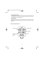
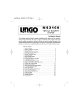
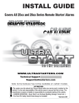
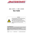
7. Remote Transmitter Layout
Arm/Lock
Disarm/Unlock
Level Shift
Auxiliary 1/
Auxiliary 2 w/
shift
Start
-6-
MS2107 install.qxd 8/25/2003 12:50 PM Page 7
8. Wiring Information
8.1 Heavy Gauge Starter Wires
RED: (+) Battery input.
This wire is one of the two primary power inputs and must be connected to the
battery or an alternate source of power that can supply at least 30 Amps.
RED: (+) Battery input.
This wire is one of the two primary power inputs and must be connected to the
battery or an alternate source of power that can supply at least 30 Amps. If both
RED wires are connected to the same power source, make sure the circuit capacity
is rated for 60 Amps.
PINK/WHITE: (+) Ignition 2 output.
Connect to the vehicle’s second ignition wire (if equipped) that switches +12V and
remains on during cranking. This wire is also programmable as accessory 2 or
starter 2 output. See Installer Programmable Features.
ORANGE: (+) Accessory output.
Connect to the wire that switches +12V to heater and/or air conditioning system. If
the vehicle has more than one accessory wire add a relay(s) to power the extra
accessory wire(s) or the PINK/WHITE wire may be programmed as accessory 2
output if not already used.
PINK: (+) Ignition 1 output.
Connect to the vehicle’s main ignition wire that switches +12V and remains on
during cranking.
VIOLET: (+) Starter output.
Connect to the starter wire coming from the key switch. If the built-in anti-grind/
starter defeat relay is used, see VIOLET/WHITE wire description.
VIOLET/WHITE: (+) Starter input (anti-grind / starter defeat).
If the antigrind / starter defeat feature is desired, follow the steps below:
1. Using a digital multi-meter, determine the wire from the ignition harness that
shows +12V only during crank. Once the wire has been found, cut the wire and
try cranking the vehicle again. The vehicle should be unable to start.
2. Connect the VIOLET/WHITE wire to the key switch side of the cut starter wire.
3. Connect the VIOLET wire to the starter motor side of the cut starter wire.
4. To verify the connections were made properly, try starting the vehicle. The
vehicle should be able to start up. If not, double check the connection at the
alarm main unit and the vehicle's starter wires.
-7-
MS2107 install.qxd 8/25/2003 12:50 PM Page 8
8.2 Main 20-Pin Harness
YELLOW: (+) Brake pedal input.
Connect to the brake pedal wire that shows +12V when the pedal is pressed. The
brake pedal input functions as a safety shutdown and must be connected.
VIOLET/WHITE: Tach input.
Connect to the vehicle’s tachometer wire or an injector wire if the tach wire is not
available. See Installer Programming Step 13 to program the tach reference after
installation. If a suitable tach wire is unable to be located, the Tachless mode may
be programmed to operate without using this wire. Note: the Tachless mode is not
recommended for extreme temperture climates.
YELLOW/BLUE: (-) Auxiliary 2 output 500mA.
Connect to a relay for an optional feature such as a linear actuator, headlight circuit,
window module, or etc. This auxiliary output can be programmed for momentary,
timed, or latched activation.
BLACK/WHITE: (-) Dome light supervision output 500mA.
Connect to a relay for optional dome light supervision upon disarming the security
system. (See Dome Light Supervision diagram for assistance.)
GRAY: (-) Trunk trigger input.
Connect to the wire that shows ground when the trunk/rear hatch is open.
GRAY/BLACK: (+) Glow plug (wait-to-start) input.
Connect to the positive glow plug wire of diesel engine equipped vehicles. This
wire should show +12 when the wait to start light is on, and will show ground when
the light turns off. For vehicle’s that show ground while the wait to start light is on,
use a relay to invert the polarity. See Glow Plug Relay Diagram.
BLUE/WHITE: (-) Passenger unlock output 500mA.
Connect to a relay to unlock the passenger doors when the system is configured
for Driver's Priority Unlocking. (See Door Lock Diagrams for assistance.
BLUE/ORANGE: (-) Ground when running output 500mA.
Connect to an optional OEM security bypass module or other device. This wire will
prove a ground output upon remote start activation, and will remain grounded until
the remote start is shutdown.
BLACK: (-) Ground input.
Connect this wire to bare metal, using a lock or star washer to prevent the screw
from coming loose. If possible, use a factory bolt, rather then a screw.
RED: +12V Battery input.
Connect to the vehicle's positive battery terminal.
-8-
MS2107 install.qxd 8/25/2003 12:50 PM Page 9
VIOLET: (+) Door trigger input.
Connect to the wire that shows +12V when the door is open.*
GREEN: (-) Door trigger input.
Connect to the wire that shows ground when the door is open.*
BLUE: (-) Hood trigger input.
Connect to the hood pin switch. Be sure this wire shows ground when the switch
is opened. This input functions as a safety shutdown and must be connected.
ORANGE: (-) Armed output 500mA.
This wire provides a ground output when the unit is armed. This wire can be used
to activate an optional circuit interrupt or other device (i.e.: window module, etc).
GREEN/BLACK: (-) Factory disarm output 125mA.
This wire provides a ground output to disarm a factory security system when the
remote is used to unlock the doors or start the vehicle.
GREEN/WHITE: (-) Factory rearm output 125mA.
This wire provides a ground output to rearm a factory security system when the
remote is used to lock the doors or when the remote start shuts down.
BROWN: (+) Siren output 3A.
Connect to the siren's red wire. Connect the black wire of the siren to (-) chassis
ground. (It is recommended to ground the siren at the same point as the main unit.)
YELLOW/WHITE: (-) Auxiliary 1 output 500mA.
Connect to a relay for an optional feature such as a trunk release solenoid, window
module, headlight activation, etc. The Auxiliary 1 output can be programmed for
momentary, timed, or latched activation.
WHITE: (+/-) Parking light output (10A relay).
The output polarity of this circuit can be selected for either (+) positive or (-)
negative output via the internal jumper. Make sure to verify the polarity of the
parking light circuit before setting the jumper.
BROWN/WHITE: (-) Horn Honk Output 500mA.
Connect to a relay to pulse the horn when the security system is triggered. (See
Horn Honk Relay Diagrams for assistance.)
* Diode isolate the door trigger wires for vehicles with separate door trigger wires.
8.3 3-Pin Door Lock Harness: (See Door Lock Diagrams for assistance.)
Green: (-) Lock
Red: Not Used
Blue: (-) Unlock
-9-
MS2107 install.qxd 8/25/2003 12:50 PM Page 10
10. Plug-in Connectors
2-PIN BLUE CONNECTOR
Plug-in connector port for Valet/Override button.
2-PIN RED CONNECTOR
Plug-in connector port for LED indicator.
4-PIN WHITE CONNECTOR (main)
Plug-in connector port for dual stage shock sensor.
4-PIN WHITE CONNECTOR (second)
Plug-in connector port for optional dual stage sensor such as an additional dual
stage shock sensor, glass breakage sensor, or dual zone proximity sensor..
3-PIN BLUE CONNECTOR
Plug-in connector port for optional Ungo-Net devices.
11. Programming Remote Transmitters
Prior to programming new remote transmitters to the security system, make sure to
have the desired transmitters ready.
11.1 To Enter Remote Transmitter Programming
To Enter Remote Transmitter Programming:
1. Turn the ignition ON, OFF, ON, OFF, and leave ON.
2. Press and hold the Valet/Override switch for 5 seconds.
The siren will chirp once.
3. Press the Lock button on the transmitter.
The siren will chirp once.
4. Press the Lock button on the transmitter again.
The siren will chirp twice.
5. Repeat steps 3 and 4 for each additional transmitter.
6. Turn OFF the ignition when transmitter programming is complete.
The siren will chirp 3 times.
11.2 Two Car Remote Operations
The 5-button remote transmitter is capable of controlling two vehicles with a single
remote transmitter. To program the primary remote transmitter to the second
vehicle, make sure to have the desired transmitter(s) ready.
-10-
MS2107 install.qxd 8/25/2003 12:50 PM Page 11
Programming the primary remote transmitter to the second vehicle:
1. Turn the ignition ON, OFF, ON, OFF, and leave ON.
The siren will chirp once.
2. Press and hold the Valet/Override switch for 5 seconds.
The siren will chirp once.
3. Press Button 5 twice followed by the Lock button on the transmitter.
The siren will chirp once.
4. Press Button 5 twice followed by the Lock button on the transmitter again.
The siren will chirp twice.
5. Repeat steps 3 and 4 for each additional transmitter.
6. Turn OFF the ignition when transmitter programming is complete.
The siren will chirp 3 times.
12. Programmable System Parameters
The Ungo MS2105/MS2107 has 2 independent programmable parameter tables.
One parameter table is for User's and the other is for Installer (see chapter 14).
These parameter tables can be modified using the Ungo-Net computer interface or
by using the Valet/Override button. The Ungo-Net interface allows for additional
custom features and settings not accessible through the Programming Table.
13. User Programmable Parameters
User Programming Table
Feature
Button 1 (default) Button 2
1.
Active
Arming Mode
2.
Auto Rearm
On
Off
3.
Arming Chirps
Normal
Silent
4.
Ignition Controlled Door Locking
On
Off
5.
Ignition Controlled Door Unlocking
All Doors
Driver’s Door
6.
Override Code Programming
Code Set
7.
Remote Start in Valet Mode
Enabled
Disabled
8.
Automatic Starting
Every 2 Hours
Every Hour
9.
Engine Run Time
15 minutes
25 minutes
-11-
Button 3
Passive
Off
MS2107 install.qxd 8/25/2003 12:50 PM Page 12
13.1 User Parameter Descriptions
1. Arming Mode: Selects whether or not the system will automatically Arm when
ignition is turned off.
2. Auto Rearming: Selects whether or not the security system will rearm if no
activity is detected after Remote Disarming. (If Passive Door Locking feature
was selected during installation, the system will also relock the doors.)
Automatic Rearming only takes place if the system was Armed (actively or
passively) for at least 10 seconds and then remotely disarmed.
3. Arming Chirps: Selects whether or not the security system will chirp when arm
and disarmed.
4. Ignition Controlled Door Locking: Selects whether or not the doors will lock
when the ignition is turned On. Ignition Controlled Door Locks will automatically
lock the doors 10 seconds after the ignition is turned On. To prevent the keys
from being locked inside the vehicle; the security system will not lock the doors
if any of the doors is open when the ignition is turned On.
5. Ignition Controlled Door Unlocking: Selects whether or not the security
system the doors will unlock when the ignition is turned Off. Ignition Controlled
Door Unlocking can be configured to unlock all the doors or driver's door only.
6. Override Code Programming: Selects the number of times the Valet button
must be depressed to override the system. The Override Code can be any
number between 1 and 15. (Default setting is 1)
7. Remote Start in Valet Mode: Selects whether or not the remote start can be
activated when the security system is in Valet mode.
8. Automatic Starting: Selects the timing interval for the ustomatic remote start
function. When the Automatic Starting feature is enabled by the user, the
vehicle will start and run every 2 hours or every hour depending on the
programming option selected for this step.
9. Engine Run Time: Selects the length of time the engine will remain running
during remote start operation.
13.2 Entering User Programming
1. Turn the ignition ON.
2. Within 5 seconds, press the Valet/Override button 2 times and hold for 2
seconds.
The siren will chirp, indicating that User Programming has been entered.
3. Press the Valet/Override button the number of times equal to the Parameter to
be changed.
The siren will chirp each time the Valet/Override button is pressed.
-12-
MS2107 install.qxd 8/25/2003 12:50 PM Page 13
4. Within 5 seconds, press the transmitter button corresponding to the desired
operating mode that Parameter.
The siren will chirp a number of times equal to the transmitter button pressed.
5. When finished, turn the ignition OFF to save changes.
13.3 Default Reset for User Programming
1. Turn the ignition ON.
2. Within 5 seconds, press the Valet/Override button 2 times and hold for 2
seconds.
The siren will chirp, indicating that Programming has been entered.
3. Press transmitter button 3.
The siren will chirp 6 times indicating the reset signal has been received, and
User Parameters have been reset to factory default.
14. Installer Programmable Parameters
Installer Programming Table
Feature
Button 1 (default) Button 2
1.
Door Unlock Pulse
Single
2.
Door Lock/Unlock Pulse Width
1 Second
3 Seconds
3.
Passive Locking
Off
On
Button 3
Double
4.
Door Entry Delay w/ Passive Arming
Off
On
5.
Ignore Dome Light Delay
Off
On
6.
Auxiliary 1 Output
Momentary
Timed
Latched
7.
Auxiliary 2 Output
Momentary
Timed
Latched
8.
Auxiliary 2 Activate on Arm
Off
On
9.
Trunk Disarm Feature
Off
On
10. Lock on Remote Start
Off
On
11. Lock on Remote Shutdown
Off
On
12. Engine Start Sense
Tach Sense
Tachless Operation
13. Program RPM
Learn RPM
Gas
14. 2-way Transmitter Module
Learn Module ID
Learn Transmitter ID
15. Ignition 2 Relay Programming
Ignition 2
Accessory 2
Diesel
Starter 2
16. Horn Output Programming
Horn
Ignition 3
Step 14 is reserved for use with optional Ungo-Net 2-way LCD transmitter module (included with MS2107).
-13-
MS2107 install.qxd 8/25/2003 12:50 PM Page 14
14.1 Installer Parameter Descriptions
1. Door Unlock Pulse: Selects between single or double unlock pulse.
2. Door Lock Pulse Width: Selects between a 1-second or 3-second door lock
pulse.
3. Passive Locking: Selects whether or not the door locks will automatically lock
with Auto Rearming and Passive Arming.
4. Door Entry Delay with Passive Arming: Selects whether or not the door
trigger input will be delayed for 15 seconds, allowing access to the Override
switch. The door trigger is delayed only when the system arms passively.
5. Ignore Dome Light Delay: Selects whether or not the security system will
ignore the door trigger for 20 seconds upon arming. For vehicles with timed
dome light delays, the system will not detect a faulty door trigger upon arming.
6. Auxiliary 1 Output: Selects between momentary, timed, or latched output for
Auxiliary 1.
Momentary: Provides an output that will remain active as long as transmitter
button is depressed.
Timed: Provides an output that will remain active for 30 seconds.
Latched: Provides an output that will activate when the transmitter button is
pressed and remain active until the the transmitter button is pressed again.
The latched output can be programmed to reset when the security system is
Armed or the ignition is turned On. (Requires the Ungo-Net computer interface
for programming.)
7. Auxiliary 2 Output: Selects between momentary, timed, or latched output for
Auxiliary 2 (see step 8 for descriptions).
8. Auxiliary 2 Activate on Arm: The security system can be programmed to
activate Auxiliary 2 when Armed. This feature can be used to turn on a piezo
warning indicator, roll up windows, etc.
9. Trunk Disarm Feature: This feature will automatically disarm the security
system when Auxiliary 1 is activated.
10. Lock on Remote Start: Selects whether or not the doors will lock after remote
starting.
11. Lock on Remote Shutdown: Selects whether or not the doors will lock after
remote start shutdown.
12. Engine Start Sense: Selects between Tach sense mode and Tachless
operation. Tach sense mode should always be used in extreme temperature
climates and in cases where the Tachless operation provides unsatisfactory
operation.
-14-
MS2107 install.qxd 8/25/2003 12:50 PM Page 15
13. Program RPM: This dual function programming step sets the engine type
(default is gas) and learns the idle tach setting.
Button 1: "Learns" the tach reference of the vehicle.
Button 2: Selects gasoline engine type.
Button 3: Selects diesel engine type.
Tach Learning notes: To learn the tach setting of the vehicle, first set the
engine type. If the vehicle is gasoline powered, then no adjustment is needed.
Next, start the engine and enter the programming mode within five seconds.
Select step 13 and press transmitter button 1 to learn. The LED will flash once
to confirm tach learning, or five times if unable to learn the tach signal.
14. 2-way Transmitter Module: (Requires Ungo-Net 2-way Transmitter Module)
Button 1: Learns the Ungo-Net 2-way module ID
Button 2: Learns the 2-way transmitter ID. Once the remote programming routine
has been entered, press button 1 on each 2-way transmitter (maximum 2).
15. Ignition 2 Relay Programming: Allows Ignition 2 output to be programmed for
use as a second ignition or second starter output instead.
16. Horn Output Programming: Allows the horn output to be programmed for use
as an output to trigger an ignition 3 relay.
14.2 Entering Installer Programming
1. Turn the ignition ON.
2. Within 5 seconds, press the Valet/Override button 5 times.
The siren will chirp, indicating that Installer Programming has been entered.
3. Press the Valet/Override button the number of times equal to the Parameter to
be changed.
The siren will chirp each time the Valet/Override button is pressed.
4. Within 5 seconds, press the transmitter button corresponding to the desired
operating mode that Parameter.
The siren will chirp corresponding to the button depressed.
5. When finished, turn the ignition OFF to save changes.
14.3 Default Reset for Installer Programming
1. Turn the ignition ON.
2. Within 5 seconds, press the Valet/Override button 5 times.
The siren will chirp, indicating that Programming has been entered.
3. Press transmitter button 3.
The siren will chirp 6 times indicating the reset signal has been received, and
Installer Parameters have been reset to factory default.
-15-
MS2107 install.qxd 8/25/2003 12:50 PM Page 16
15. System Test and Sensor Adjustment
15.1 System Test
1. Verify the Programmable Parameters are set.
2. Verify all wire connections are correct and secure.
3. Make sure none of the wires for the security system will interfere with safe
operation of the vehicle.
4. Test all functions of the vehicle, i.e. power door locks, power windows, lights,
etc.
5. Arm the security system; checking the siren chirps, parking lights, LED, and
door locks.
6. Disarm the security system; checking the siren chirps, parking lights, LED, door
locks, and dome light supervision.
7. Test all the entry points of the vehicle, doors, hood, and trunk/hatch. (Be sure
to test all doors.)
15.2 Dual Stage Sensor Test
1. Turn the ignition On.
2. Within 4 seconds, press the Shift Button (Button 5) 3 times, then Button 3.
The siren will chirp 4 times indicating the sensor is ready to be tested.
3. Test the sensitivity of the sensor by hitting various locations on the vehicle. (Do
hit the windshield or any other window. Be careful not to dent or damage any
parts of the vehicle during shock sensor testing.)
The siren will chirp when a trigger impact is detected.
One chirp indicates the shock sensor trigger.
Two chirps indicates the warn-away trigger.
Three chirps indicates the optional sensor.
4. To make shock sensor adjustments:
Turn the adjustment screw on the shock sensor clockwise to increase the
sensitivity.
Turn the adjustment screw on the shock sensor counter clockwise to
decrease the sensitivity.
5. Turn the ignition Off when the desired sensitivity level is reached.
-16-
MS2107 install.qxd 8/25/2003 12:50 PM Page 17
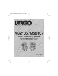
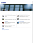
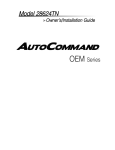
16. Parking Light Jumper Settings
The Parking Light Polarity Jumper selects the polarity (+/-) for the output of the
on-board Parking Light relay.
Negative
Positive
17. Optional Circuit Interrupt
-17-
MS2107 install.qxd 8/25/2003 12:50 PM Page 18
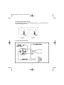
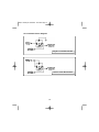
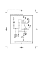
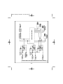
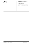
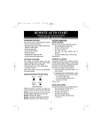
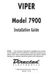
18. Dome Light Supervision Relay Diagrams
Negative Door Pinswitch
Positive Door Pinswitch
-18-
MS2107 install.qxd 8/25/2003 12:50 PM Page 19
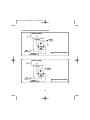
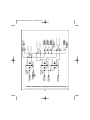
19. Trunk/Hatch Release Diagrams
Negative Trunk Release Wire
Positive Trunk Release Wire
-19-
MS2107 install.qxd 8/25/2003 12:50 PM Page 20
20. Horn Honk Wiring Diagrams
Negative Horn Trigger
Positive Horn Trigger
21. Negative Glow Plug Diagram
Negative Glow Plug
-20-
MS2107 install.qxd 8/25/2003 12:50 PM Page 21
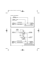
22. Door Lock Diagrams
Negative Door Lock System
Positive Door Lock System
-21-
MS2107 install.qxd 8/25/2003 12:50 PM Page 22
Reverse Polarity Door Lock System
-22-
MS2107 install.qxd 8/25/2003 12:50 PM Page 23
Actuator Diagram
-23-
MS2107 install.qxd 8/25/2003 12:50 PM Page 24
Vacuum Pump System
-24-
MS2107 install.qxd 8/25/2003 12:50 PM Page 25
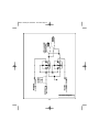
23. Driver’s Door Priority Wiring Diagrams
Negative Door Lock System with Driver’s Door Priority
-25-
MS2107 install.qxd 8/25/2003 12:50 PM Page 26
Positive Door Lock System with Driver’s Door Priority
-26-
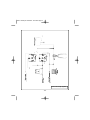
MS2107 install.qxd 8/25/2003 12:50 PM Page 27
Reverse Polarity Door Lock System with Driver’s Door Priority
-27-
MS2107 install.qxd 8/25/2003 12:50 PM Page 28
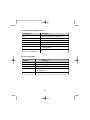
24. Status Indicator (LED) Functions
LED STATUS
FUNCTION
Off
Slow Flash
Rapid Flash
Rapid Flash (after disarm)
On Solid
On Solid (after arming)
System is disarmed in Active mode.
System is Armed.
Passive arming indication and auto rearm.
System was triggered.
Valet mode.
On for 3 seconds, shock sensor trigger has
been bypassed.
Door or hood/trunk is open.
On Solid (when disarmed
and not in Valet mode)
25. Siren Chirp Status
CHIRPS
1 Chirp
2 Chirps
3 Chirps
4 Chirps
5 Rapid Chirps
FUNCTION
System Armed
System Disarmed
System Disarmed, but alarm triggered while away.
10 seconds after arming indicates defective sensor
or trigger zone.
Warn away triggered.
-28-
MS2107 install.qxd 8/25/2003 12:50 PM Page 29
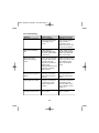
26. Troubleshooting
Symptom
Probable Cause
Suggested Correction
Alarm doesn't Arm/Disarm.
Alarm in Valet Mode.
Ignition input has voltage
on it. Missing +12 or
ground.
Take alarm out of Valet
mode. Turn key off and
verify pink wire is
connected to correct
ignition wire. Check +12V
and ground connections.
Alarm will not Passively
Arm.
Passive arming is
programmed Off. Wrong
door switch polarity. Alarm
in Valet mode.
Change arming mode to
Passive arming. Change
ignition input. Make sure
alarm is not in Valet.
Alarm will not enter
Remote programming
mode.
Ignition was not left in the
On position after turning it
On & Off three times.
Sequence not performed
rapidly enough.
Valet/Override switch is not
plugged in or defective.
Alarm is armed.
Repeat procedure quicker.
Check connection on Valet
button. Make sure the
alarm is not in Valet or
Armed.
Alarm chirps 4 times 10
seconds after the system is
Armed.
Factory Dome light delay is
longer than 10 seconds.
Door switch or sensor is
defective.
Set parameter for Ignore
Dome Light Delay to On.
Adjust or replace shock
sensor.
Parking lights do not flash.
Wrong wire connected to
the White wire. Polarity
selection needs to be
changed.
Correct the connection to
the parking light wire.
Move the jumper next to
relay on board to correct
polarity (+/-).
System Arms and Disarms,
but doesn't chirp the siren.
Arming Chirps has been
set to " Silent."
Set parameter for Arming
Chirp to "Normal."
-29-
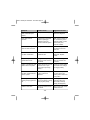
MS2107 install.qxd 8/25/2003 12:50 PM Page 30
Symptom
Probable Cause
Suggested Correction
Dome light supervision
does not activate upon
Disarm.
Relay wired incorrectly.
See Dome Light
Supervision diagrams.
Poor range with the
remotes.
Antenna wire is grounded.
Module is picking up
interference from the
vehicle's electrical system.
Make sure the antenna is
not connected to ground.
Relocate module or route
antenna away from
computer modules.
Vehicle starts using the key
when the alarm is Armed.
Wrong starter wire is cut.
Locate the proper starter
wire and reconnect the
other wire.
Vehicle will not start when
the alarm is Disarmed.
Bad connection on violet or
violet/white wire.
Repair connection at
starter wire. Replace
module.
Keyless entry does not
operate with remote.
Wrong door lock polarity.
Wrong door lock wires are
connected.
See Door Lock Diagrams.
Verify the vehicle's door
lock wires.
Ignition controlled door lock
feature does not operate.
Ignition wire shows +12V at
all times. Door is open.
Door trigger input wrong
polarity.
Connect to correct ignition
wire. Close door. Change
door trigger polarity.
Vehicle's horn honks when
the alarm is Disarmed and
door is opened.
Vehicle factory security
system needs to be
disarmed.
Locate the factory disarm
wire and use the door
Unlock pulse to disarm the
factory alarm.
Diesel engine cranks
before glow plug light turns
off.
Wrong glow plug wire or
wire not connected. Wrong
glow plug wire polarity.
Connect gray/black wire to
proper glow plug wire.
Use a relay to change
polarity (see diagrams).
Unable to learn tach.
Wrong tach reference wire
connected.
Using a multi-meter locate
another tach wire.
-30-
MS2107 install.qxd 8/25/2003 12:50 PM Page 31
27. Warranty Information
This Ungo Security System is warranted against defects in material and workmanship. The main unit
and remote controls are covered by this limited lifetime warranty. This Limited Lifetime Warranty applies
to Ungo Security systems that have been installed by an authorized Ungo Security dealer. This warranty
is to the Original Purchaser ("Owner") and to the original vehicle in which it was installed into. This
warranty is not transferable to any subsequent owner(s) of the product(s).
Warranty Program:
Main Unit
Remote Controls
LCD Remote Control
Siren
Shock Sensor
LED
Valet/Override Button
Limited Lifetime
Limited Lifetime
Three years from date of purchase
One year from date of purchase
One year from date of purchase
One year from date of purchase
One year from date of purchase
The Warranty does not cover batteries or products deemed damage through alterations or installation. It
also does not cover products mishandled, misused, neglected, abused, water damaged, or with
removed/altered serial numbers.
PROOF OF PURCHASE WILL BE REQUIRED FOR WARRANTY SERVICE OF THIS PRODUCT.
This warranty does not cover the costs incurred for removal or reinstallation of the main unit and/or any
damage to the vehicle or the vehicle's electrical system.
The sole responsibility of Clarion Corporation under this Warranty shall be limited to the repair or
replacement of the product, at the sole discretion of Clarion Corporation.
If it becomes necessary to send the product or any defective part to Clarion Corporation, the product
must be shipped in its original carton or equivalent carton, fully insured, with shipping charges prepaid.
Clarion Corporation will not assume any responsibility for any loss or damage incurred in shipping.
ALL IMPLIED WARRANTIES EXCEPT TO THE EXTENT PROHIBITED BY APPLICABLE LAW SHALL
HAVE NO GREATER DURATION THAN THE WARRANTY PERIOD SET FORTH ABOVE. UNDER NO
CIRCUMSTANCES SHALL CLARION CORPORATION BE LIABLE FOR ANY LOSS OR DAMAGE,
DIRECT OR CONSEQUENTIAL, ARISING OUT OF THE USE OR INABILITY TO USE OF THE
PRODUCT. BECAUSE SOME STATES DO NOT ALLOW LIMITATIONS ON HOW LONG AN IMPLIED
WARRANTY LASTS OR EXCLUSIONS OR LIMITATIONS OF INCIDENTAL OR CONSEQUENTIAL
DAMAGES, THE ABOVE LIMITATIONS OR EXCLUSIONS MAY NOT APPLY TO YOU.
THIS WARRANTY GIVES YOU SPECIFIC LEGAL RIGHTS, AND YOU MAY ALSO HAVE THE OTHER
RIGHTS, WHICH VARY FROM STATE TO STATE.
Should you have any difficulties with the performance of this product during warranty, please call: 1-800GO-CLARION or visit your local Ungo dealer. You may also contact the National Service Manager at the
following address below for additional service help you may need.
Clarion Corporation of America
Attn: National Service Manager
661 W. Redondo Beach Blvd.
Gardena, Ca 90247
-31-
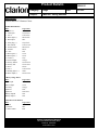
Product Bulletin
PB00015
Category:
Ungo
Subject:
MS2105/7 Wiring Harness
Description:
UNGO MS2105/7 Harness Colors
20-Pin Main Harness
Wire
1 Brake (+)
2 Tach input
3 Aux 2
4 Dome light (-)
5 Hood input
6 Glow plug (+)
7 Pass Unlock
8 Ground w/run
9 Ground
10 +12V
11 Door input (+)
12 Door input (-)
13 Trunk (-)
14 Armed output
15 Factory disarm
16 Factory arm
17 Siren
18 Aux 1
19 Parking light (+/-)
20 Horn output (-)
Ungo Color
Yellow
Violet/white
Yellow/blue
Black/white
Blue
Gray/black
Yellow/violet
Blue/black
Black
Red
Violet
Green
Gray
Orange
Green/black
Green/white
Brown
Yellow/white
White
Brown/white
7 Heavy Gauge Wires
Wire
Starter input
Starter output
Accessory
Ignition 1
Ignition 2
Battery Input B
Battery Input A
Ungo Color
Violet/white
Violet
Orange
Pink
Pink/white
Red
Red
3-Pin Door Lock Harness
Wire
Ungo Color
(-) Lock
Green
(-) Unlock
Blue
** NOT USED
Red
Clarion Corporation of America
661 West Redondo Beach Blvd.
Gardena, CA 90247
www.clarion.com
Date:
12-2-03