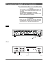
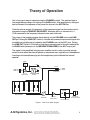
1
ADINSTRUMENTS
making science easier
MA3300 Audio
Monitor
Owner’s Guide
ADINSTRUMENTS
making science easier
This document was, as far as possible, accurate at the time of release. However, changes may have been made
to the software and hardware it describes since then. ADInstruments Pty Ltd. reserves the right to alter
specification as required. Late-breaking information may be supplied separately.
Trademarks of ADInstruments
PowerLab®, LabChart®, LabTutor®, LabAuthor® and MacLab® are registered trademarks of
ADInstruments Pty Ltd. The names of specific recording units, such as PowerLab 8/35, are trademarks
of ADInstruments Pty Ltd. LabTutor Server, Chart and Scope (application programs) and LabTutor
Online are trademarks of ADInstruments Pty Ltd.
Other Trademarks
Apple, Mac and Macintosh are registered trademarks of Apple Computer, Inc.
Windows, Windows 7 and Windows Vista are either registered trademarks or trademarks of Microsoft
Corporation.
All other trademarks are the property of their respective owners.
Product: MA3300 Audio Monitor
Copyright © April 2014 ADInstruments Pty Ltd.
Unit 13, 22 Lexington Drive, Bella Vista, NSW 2153, Australia
All rights reserved. No part of this document may be reproduced by any means without the prior written
permission of ADInstruments Pty Ltd.
Web: www.adinstruments.com
Technical Support: [email protected]
Documentation: [email protected]
ADInstruments Pty Ltd. ISO 9001:2008 Certified Quality Management System
Reg. No. 1053
General Description
Instrument Features
The Model 3300 Audio Monitor is a high quality audio amplifier designed to transform
electrophysiological signals into sounds. This amplifier features a built-in 6-band audio
equalizer that enables the user to tailor the audio performance to their personal
satisfaction, a high-fidelity quality speaker, a dedicated notch filter designed to minimize
noise interference generated by power lines, a headphone jack, and an BNC line out jack
that enables the the Model 3300 to be used as another signal amplifier prior to
subsequent processing by other instruments.
The instrument can be placed on a lab bench with its built-in metal stand, or it can be
mounted in any industry standard equipment rack (with included rack-mounting hardware).
In addition, the instrument is shipped with it’s own desktop power supply.
It can be used in a number of research or teaching applications requiring the audio
reproduction of electrophysiological signals, such as such as nerve, muscle (EMG), EEG,
EKG, and ERG recordings.
The instrument is not intended for clinical measurements using humans.
Two input signals can be passed to the Model 3300. A toggle switch selects which of the
two signals will be amplified and processed by the 6-band equalizer. The Equalizer is a
tunable filter that can increase or decrease the gain of particular frequency ranges,
resulting in a pleasing sound quality produced at the speaker. The use of a set of
headphones (by utilizing the mini-headphone jack) will disable the internal audio speaker.
The volume control acts as a variable gain amplifier, and adjusts the volume of the
speaker output. The processed signal can be passed to an oscilloscope or other
instruments via the Signal Out BNC jack.
A-M Systems, Inc.
131 Business Park Loop, P.O. Box 850 Carlsborg, Wa 98324
Telophone: 800-426-1306 * 360-683-8300 * FAX: 360-683-3525
E-mail: [email protected] * Website: http://www.a-msystems.com
1
HDANGER
HWARNING
HCAUTION
This alerts the user to imminent death or serious injury arising
from misuse of the stimulator.
This alerts the user to possible death or serious injury arising
from misuse of the stimulator.
This alerts the user to possible injury or damage to property
arising from misuse of the stimulator.
Notes are also provided in this manual to alert the user to specific instructions or
recommendations.
General
WARNING
This device is designed for experimental and research
applications and must not be used for therapeutic purposes.
Precautions regarding settings
H CAUTION
Always use the supplied 3-pin cable for the power cable.
If any other power cable is used, it may result in an electric
shock to the operator.
H CAUTION
H CAUTION
If this instrument is connected to other peripheral devices, be
sure that they are connected in the manner specified by the
manufacturer.
Only connect devices specified by the manufacturer.
Connection to non-specified devices may result in electric
shock to the operator by current of leakage.
Do not touch the connector pins. Discharge electrostatic
energy by touching a grounded metal part before connecting.
The instrument may be damaged by electrostatic energy.
Precautions regarding maintenance
H CAUTION
When maintaining (cleaning, sterilizing, etc.) the stimulator, be
sure to turn the power off and unplug the power cable from the
power outlet first.
Failure to do so may result in an electric shock or malfunction.
H CAUTION
The electronic stimulator has a high voltage output capacity of
up to ±50 V.
Directly touching the output terminals or electrodes during
stimulation or when the power cord is connected during
inspection and the stimulator is operable may result in electric
shock.
CAUTION - 1
GENERAL HANDLING PRECAUTIONS
This device is intended for use only by qualified medical personnel.
Use only our approved products with this device. Use of non-approved products or in a nonapproved manner may affect the performance specifications of the device. This includes, but is
not limited to, batteries, recording paper, pens, extension cables, electrode leads, input boxes
and AC power.
Please read these precautions thoroughly before attempting to operate the instrument.
1. To safely and effectively use the instrument, its operation must be fully understood.
2. When installing or storing the instrument, take the following precautions:
(1) Avoid moisture or contact with water, extreme atmospheric pressure, excessive humidity and temperatures, poorly
ventilated areas, and saline or sulphuric air.
(2) Place the instrument on an even, level floor. Avoid vibration and mechanical shock, even during transport.
(3) Avoid placing in an area where chemicals are stored or where there is danger of gas leakage.
(4) The power line source to be applied to the instrument must correspond in frequency and voltage to product
specifications, and have sufficient current capacity.
(5) Choose a room where a proper grounding facility is available.
3. Before Operation
(1) Check that the instrument is in perfect operating order.
(2) Check that the instrument is grounded properly.
(3) Check that all cords are connected properly.
(4) Pay extra attention when the instrument is combined with other instruments to avoid misdiagnosis or other problems.
4. During Operation
(1) The instrument must receive continual, careful attention.
(2) Turn power off or remove electrodes and/or transducers when necessary to assure the safety.
5. To Shutdown After Use
(1) Turn power off with all controls returned to their original positions.
(2) Remove the cords gently; do not use force to remove them.
(3) Remove the power cord from the AC SOURCE socket to isolate the instrument from the AC supply mains.
(4) Clean the instrument together with all accessories for their next use.
6. The instrument must receive expert, professional attention for maintenance and repairs. When the instrument is
not functioning properly, it should be clearly marked to avoid operation while it is out of order.
7. The instrument must not be altered or modified in any way.
8. Maintenance and Inspection:
(1) The instrument and parts must undergo regular maintenance inspection at least every 6 months.
(2) If stored for extended periods without being used, make sure prior to operation that the instrument is in perfect
operating condition.
(3) Technical information such as parts list, descriptions, calibration instructions or other information is available for
qualified user technical personnel upon request from your distributor.
Operator’s Manual 1001
i
CAUTION
United States law restricts this device to sale by or on the order of a physician.
ii
Operator’s Manual 1001
EMC RELATED CAUTION
This equipment and/or system complies with the International Standard IEC 60601-2 for electromagnetic
compatibility for medical electrical equipment and/or system. However, an electromagnetic environment
that exceeds the limits or levels stipulated in IEC 60601-1-2, can cause harmful interference to the
equipment and/or system or cause the equipment and/or system to fail to perform its intended function
or degrade its intended performance. Therefore, during the operation of the equipment and/or system, if
there is any undesired deviation from its intended operational performance, you must avoid, identify and
resolve the adverse electromagnetic effect before continuing to use the equipment and/or system.
The following describes some common interference sources and remedial actions:
1. Strong electromagnetic interference from a nearby emitter source such as an authorized radio station
or cellular phone:
Install the equipment and/or system at another location. Keep the emitter source such as cellular
phone away from the equipment and/or system, or turn off the cellular phone.
2. Radio-frequency interference from other equipment through the AC power supply of the equipment
and/or system:
Identify the cause of this interference and if possible remove this interference source. If this is not
possible, use a different power supply.
3. Effect of direct or indirect electrostatic discharge:
Make sure all users and patients in contact with the equipment and/or system are free from direct or
indirect electrostatic energy before using it. A humid room can help lessen this problem.
4. Electromagnetic interference with any radio wave receiver such as radio or television:
If the equipment and/or system interferes with any radio wave receiver, locate the equipment and/or
system as far as possible from the radio wave receiver.
5. Interference of lightning:
When lightning occurs near the location where the equipment and/or system is installed, it may induce
an excessive voltage in the equipment and/or system. In such a case, use an uninterruptible power
supply.
6. Use with other equipment:
When the equipment and/or system is adjacent to or stacked with other equipment, the equipment and/
or system may affect the other equipment. Before use, check that the equipment and/or system
operates normally with the other equipment.
7. Use of unspecified accessory, transducer and/or cable:
When an unspecified accessory, transducer and/or cable is connected to this equipment and/or
system, it may cause increased electromagnetic emission or decreased electromagnetic immunity.
The specified configuration of this equipment and/or system complies with the electromagnetic
requirements with the specified configuration. Only use this equipment and/or system with the
specified configuration.
Caution - continued
Operator’s Manual 1001
iii
8. Use of unspecified configuration:
When the equipment and/or system is used with the unspecified system configuration different than
the configuration of EMC testing, it may cause increased electromagnetic emission or decreased
electromagnetic immunity. Only use this equipment and/or system with the specified configuration.
9. Measurement with excessive sensitivity:
The equipment and/or system is designed to measure bioelectrical signals with a specified sensitivity.
If the equipment and/or system is used with excessive sensitivity, artifact may appear by
electromagnetic interference and this may cause mis-diagnosis. When unexpected artifact appears,
inspect the surrounding electromagnetic conditions and remove this artifact source.
If the above suggested remedial actions do not solve the problem, consult your distributor for additional
suggestions.
NOTE about Waste Electrical and Electronic Equipment (WEEE) directive 2002/96/EEC
For the member states of the European Union only:
The purpose of WEEE directive 2002/96/EEC is, as a first priority, the prevention of waste electrical and
electronic equipment (WEEE), and in addition, the reuse, recycling and other forms of recovery of such
waste so as to reduce the disposal of waste.
Contact your representative for disposal at the end of its working life.
iv
Operator’s Manual 1001
Contents
Introduction ................................................... 2
Specifications .............................................. 35
Features ............................................................ 2
Configuration ..................................................... 3
Stimulation Trigger ........................................... 35
Peripheral Devices ................................................. 3
Stimulation Waveform Setup ........................... 35
Stimulation Output ........................................... 36
Synchronized Output Signal ............................ 37
Language ......................................................... 37
Power Source .................................................. 37
Environment .................................................... 37
Electronic Stimulator 1001 Hardware Configuration ....... 4
Precautionary Labels and Indications ........... 5
Front .................................................................. 5
Rear ................................................................... 5
Main Interval ......................................................... 35
List of Symbols .............................................. 6
Operating Environment ........................................ 37
Storage Environment ........................................... 37
Description of Parts ....................................... 7
Durability .......................................................... 38
Installation ....................................................... 38
Safety Standards ............................................. 38
Dimensions and Weight ................................... 38
Electromagnetic Compatibility ......................... 38
Front .................................................................. 7
Power On/Off ......................................................... 7
Keys and Dial ......................................................... 7
Main Interval ........................................................... 8
External Trigger (EXT TRIG) ................................ 10
Stimulation Waveform Setup ................................ 12
Stimulation Waveform Output .............................. 14
BIPHASIC, MIX, MODU, DC, ALTN ..................... 16
Memory ................................................................ 18
Rear ................................................................. 19
Power ................................................................... 19
External Signal Input Terminals ............................ 20
Synchronizing Signal Output Terminal ................. 22
Serial Output ........................................................ 23
General Handling Precautions .................... 24
Preparation .................................................. 26
Installing the Serial Converter Driver Software 26
Scope Settings ................................................ 29
Installing the Stimulator ................................... 33
Connection of Cables ...................................... 33
Introduction
The electronic stimulator is used for the basic physiological and
pharmacological research and experiments.
WARNING
This device is designed for experimental and research
applications and must not be used for therapeutic purposes.
By simple operation of the panel, a single pulse, pair pulse, train pulse
and repeat pulse according to main interval can be output, as well as
various mixed waveforms in combination with an external signal, and a
biphasic pulse.
The stimulator is also equipped with a booster amplifier to allow field
stimulation.
Features
/Simple train stimulation
A single pulse, pair pulse or train pulse can easily be output.
/Built-in main interval function, independent of stimulation waveform
setup
Starting/Stopping and the repeat time and repeat count can be set separately
using the main interval function, ensuring simple, reliable operation.
/Field stimulation
The built-in booster amplifier with a maximum output of ±50 V and 400
mA enables direct field stimulation with any stimulation waveform.
/Simple biphasic pulse stimulation
/Mixing and modulation input terminals that allow output of mixed and
modulated waves through combination with an external signal
/Alternate stimulation by the addition of an evoked response to eliminate
stimulation artifacts
/Output of information to an external device such as a Power Lab
All set stimulation conditions and operating information can be output
from the USB port to an external device.
/High precision, high reliability design
By adopting a crystal oscillator as the internal base oscillation source and
combined with IC technology, time-related items can be controlled with
extreme precision, ensuring excellent reliability and reproducibility as well
as stable operation.
/Fine adjustment of output voltage
The output voltage setting can be adjusted up to 10 V.
/Input/Output protection circuit
The built-in protection circuit prevents damage in the event of an accidental
short circuit in the output terminal or synchronization signal output terminal
or excessive voltage (max. 50 V) to the input terminal.
2 Introduction
Configuration
Peripheral Devices
Oscilloscope
Data Processor
Setup Data
Computer
TRIG
to ISO
Electronic Stimulator 1001
OUTPUT
Patch Clamp Amplifier
Isolator
Microelectrode Amplifier
Membrane Potential Fixing
Amplifier
[Fig.1]
Introduction 3
Electronic Stimulator 1001 Hardware Configuration
F-ROM
for writing
Serial 1
Communications
Unit
Serial 0
Communications
Unit
SCI-A
SCI-B
Settings
TRIG
LEVEL
to Data Processor
EEPROM
Stimulation
Output
Voltage
Stimulation
Signal
Amplifier
Isolator
Range
Information
Stimulation Voltage
(Detected Value)
[Fig.2]
4 Introduction
Precautionary Labels and Indications
See the relevant reference page for details of each label or indication.
H CAUTION
If this instrument is connected to other peripheral devices, be
sure that they are connected in the manner specified by the
manufacturer.
Only connect devices specified by the manufacturer.
Connection to non-specified devices may result in electric
shock to the operator by current of leakage.
H CAUTION
Do not touch the connector pins. Discharge electrostatic
energy by touching a grounded metal part before connecting.
The instrument may be damaged by electrostatic energy.
Front
[Fig.3]
See P.1-14
Rear
6
7
OUTPUT
STOP
MAIN SET CYCLES
INTERVAL
END
EXT
TRIG
F
MAIN KEY
START
MIX
MODU
DELAY
INTERVAL
See P.1-20, 1-22
TRAIN
END
OFF
U S E
"
to PC
SPEAKER
EXT
TRIG
U S E
F
INPUT
MAIN
START
ON
See P.1-23
1AC SOURCE
[Fig.4]
Precautionary Labels and Indications 5
List of Symbols
The following symbols are used in connection with the stimulator.
An explanation of each symbol is given in the table below.
* When the description of a symbol used for the stimulator differs from
JIS standards, it is shown in brackets.
Symbol
H
8
9
F
G
1
Description
Caution / See attached materials
Power ON
Power OFF
Symbol
"
6
7
Description
[Serial I/O Terminal]
Input [Terminal]
Output [Terminal]
ON position [Power ON]
Equipotential Ground [Terminal]
OFF position [Power OFF]
[Positive Polarity]
Alternative Current (AC)
[Negative Polarity]
The products marked with this symbol apply to the European WEEE directive 2002/96/EEG
and require separate waste collection. For the products labeled with this symbol, contact your
representative for disposal at the end of its working life.
6 List of Symbols
Description of Parts
Front
Main Interval
Memory
Power On/Off
Stimulation Waveform Setup
Stimulation Waveform Output
[Fig.5]
External Trigger Biphasic•EMixing•EModulation•EDC Dial
Power On/Off
This button is used to turn the power on and off.
[Fig.6]
Name
1
1Power Button
2Power Indicator Lamp
2
Function
When the power button is pressed (ON position), the power indicator lamp
lights and the power is turned on. To turn the power off, press the button again.
When the power is turned on, all the LEDs light once (self-check).
Keys and Dial
Used to increase or decrease the set values. (See P.2 for details.)
4
[Fig.7]
3
Name
Function
3Keys
Press to adjust the set values. The indicator for the selected key blinks. The set
value changes each time the key is pressed.
4Dial
Adjusts the set value selected with the selector key. Turn clockwise to increase
the value and counterclockwise to decrease the value.
When the dial is pressed, the last selected set value blinks and is set.
Description of Parts 7
Main Interval
Controls the repeat cycle (T1) and repeat count (N1) as well as starting
and stopping of stimulation.
(The timing signal created here acts becomes the trigger as MAIN
INTERVAL and is not a direct stimulation waveform.)
5
6 7
A
[Fig.8]
8 9
Name
Function
5Stimulation interval (T1)
indicator (MAIN INTERVAL)
Displays the repeat interval (T1) setting.
Setting range: 1 ms to 9990 s
6Stimulation count indicator
(CYCLES)
Displays the repeat count (N1) setting.
/CYCLES switches from displaying the repeat count (CYCLES) to displaying
the repeat setting (SET CYCLES). (Normally CYCLES is displayed and the
indicator is lit.)
/When the selector key is pressed, the display changes to SET CYCLES and
the indicator blinks. (It automatically returns to CYCLES after about 10
seconds.)
/SET CYCLES can be changed by turning the dial while the indicator is
blinking.
/While CYCLES is displayed, it is synchronized with stimulation output and
shows the stimulation count.
Setting range: 1 to 999 or to continuous operation (run).
When the START signal is received, the set number of pulses is output by MAIN
INTERVAL at the set interval (T1) and operation stops.
When continuous operation is set (run), after the START signal is received, the
MAIN INTERVAL signal continues to be sent at the set interval (T1).
Operation continues until the STOP key is pressed.
7Stimulation count cancel key
(RESET)
Resets the stimulation repeat count.
8Stimulation start key
(START <MANUAL>)
Used to start stimulation manually.
When this key is pressed, MAIN INTERVAL operation Starts.
The START key is disabled during MAIN INTERVAL operation. (No restart.)
9Stimulation stop key
(STOP <MANUAL>)
Used to stop stimulation manually.
When this key is pressed, MAIN INTERVAL and all other operation stops and
the stimulator returns to initial status.
8 Description of Parts
Name
Function
AMAIN INTERVAL operation lamp Lights when MAIN INTERVAL is operating.
(As it is sometimes difficult to tell whether MAIN INTERVAL is operating
when a long interval has been set, operation can be judged by checking the
lamp.)
Disabled
MAIN
INTERVAL
signal
Operating
Stopped Operating
[Fig.9] MAIN INTERVAL operation when SET CYCLES is set to 008
Description of Parts 9
External Trigger (EXT TRIG)
Like MAIN INTERVAL, this generates a trigger pulse. It is used to control
the stimulation repeat cycle by an external signal.
When EXT is selected with the trigger selector button, stimulation occurs
in synchronization with the signal that is input to the external trigger
terminal on the rear of the stimulator.
B
10 Description of Parts
[Fig.10]
Name
Function
BTrigger level adjustment knob
(EXT TRIG LEVEL)
Selects whether the trigger is activated at the signal level that is input to the
external trigger terminal (on rear).
Adjustment range: 0 to ±10 V.
If the sweep-wave output from the oscilloscope is used as the external trigger
signal, the stimulation pulse can be monitored at any position on the oscilloscope
tube by setting the level adjustment knob.
Allowing for a noise margin and hysteresis in the built-in comparator, use a
trigger signal to oscillate up to about 1 V lower than the trigger level.
External
trigger
signal
External trigger pulse
Approx. 1 V or more is needed
[Fig.11]
When set to SYNC
When the knob is turned fully counterclockwise until it locks (SYNC position),
the trigger level is approximately +3 V.
When activating the trigger at a pulse of +5 V, the inconvenience of setting
the level can by avoided by using this position.
Description of Parts 11
Stimulation Waveform Setup
This component receives the main interval trigger signal, external trigger
signal, etc., sets the stimulation wave and timing and sends the signal
for stimulation output.
The stimulation wave is determined by the four parameters in the figure
below.
Trigger
Stimulation wave
Delay signal
Train end signal
Interval signal
[Fig.12]
T2 = DELAY: delay time from trigger to start of stimulation
T3 = DURATION: duration of stimulation pulse
T4= INTERVAL: interval between stimulation pulses
n = TRAIN: number of stimulation pulses
D E
C
12 Description of Parts
F
G
H
[Fig.13]
Name
Function
CTrigger signal selector key
(MAIN, EXT)
Selects a trigger signal. The lamp for the selected key lights.
MAIN: Signal generated by MAIN INTERVAL described above
EXT: Signal generated by EXTERNAL TRIGGER described above
DDelay time display
(DELAY)
Sets the delay time (T2) until the channel outputs a stimulation pulse after the
trigger signal is received. The timing is shown in Fig.12.
Number
3 digits
EStimulation pulse interval
display (INTERVAL)
display (TRAIN)
Setting range
100 µsec to 999 sec
Unit
s, ms, µs
Sets the stimulation pulse duration (T3). The timing is shown in Fig.12.
Number
3 digits
GStimulation pulse count
Unit
s, ms, µs
Sets the pulse interval (T4) when the number of stimulation pulses is set by
TRAIN to 2 pulses or more or to continuous stimulation (run). The timing is
shown in Fig.12.
Number
3 digits
FStimulation pulse duration
display (DURATION)
Setting range
0-99.9 sec
Setting range
10 µsec to 99.9 sec
Unit
s, ms, µs
Sets the number (n) of stimulation pulses.
Fig.12 shows an example when n=5.
Setting range: 0 to 999.
Single pulse stimulation occurs at n=001, pair pulse stimulation at n=002 and
train pulse stimulation at n=003 or over.
Trigger signal
n=1 Single pulse
n=2 Pair pulse
n=3 or over
Train pulse
[Fig.14]
When run (set value: 000) is set, continuous stimulation occurs. After the trigger
is initiated and the delay time has elapsed, pulse output continues at the set
interval (T4).
Continuous stimulation continues until the STOP button is pressed.
The following trigger signals are disabled during stimulation.
HMonitor lamp
(OUTPUT)
Stimulation pulse monitor lamp.
It lights for at least 50 ms in synchronization with the stimulation pulse.
If the duration of the stimulation pulse is 50 ms or more, the lamp stays lit for
the duration of the pulse.
As the purpose of the lamp is to monitor the timing of the stimulation pulse, it
operates regardless of the polarity selector key, VOLTAGE setting or MIX key.
Description of Parts 13
Stimulation Waveform Output
This sets the polarity of the waveform generated by stimulation waveform
setup and the output voltage.
J
M
L
[Fig.15]
I
Name
K
Function
IPolarity selector key
(
, OFF,
)
Switches the polarity of the stimulation pulse.
indicates positive polarity
and
negative polarity.
The selection governs both the isolator connector and the output terminals.
Output is 0 V when OFF is selected.
JOutput voltage display
(VOLTAGE)
Sets the output voltage of the stimulation waveform. Setting is performed by
the same method as for other settings.
Normally, setting is 0 mV or from 10 mV to 10 V. If ±50 V is selected, setting is
0 mV or from 10 mV to 50 V. (1 mV to 9 mV cannot be set.)
This setting does not affect the mixing signal or modulation signal. DC voltage
in DC mode is also set.
When negative polarity ( ) is selected with the polarity selector key, it is read
as it is as minus voltage. Output precision in relation to the command is within
±5% ±50 mV.
14 Description of Parts
Name
Function
KOutput selector key
(±50 V / ±10 V)
When the key is pressed, the lamp lights and 5 times the normal voltage of 0 to
±10 V is supplied to the output terminal.
This can be used for field stimulation.
(max. 0 to ±50 V, 400 mA)
Additionally, key operation does not affect output to the isolator (to ISO
connector).
Lto ISO
(Isolator output connector)
Drives the isolator when connected to the connector.
Pin No.
Signal
1, 2 +15V
3 –15V
4 SIGNAL OUT
5 Range data
6 E
7 Range data synchronizing clock
8, 9, 10 Void
[Fig.16]
MOutput terminal
As the output waveform is the same as that of the isolator output connector, this
is useful for monitoring the stimulation waveform.
It can also be used for the stimulation signal to the microelectrode amplifier or
membrane potential fixing amplifier .
However, when output is switched to ±50 V, the waveform is not the same as
the isolator output connector signal, and five times the voltage is generated.
Use this terminal directly for field stimulation.
[Note] Take care to avoid short-circuiting during stimulation, otherwise
no stimulation will occur.
Description of Parts 15
BIPHASIC, MIX, MODU, DC, ALTN
These keys are used when stimulation is performed by biphasic wave, a
composite wave created by mixing with an external waveform, a waveform
where the external signal has been modulated by internal oscillation, or
with DC voltage.
N
O
P QRS
[Fig.17]
Function
Name
N Biphasic waveform key
(BIPHASIC)
Press to output a biphasic waveform. (The lamp lights.)
OBiphasic negative polarity
voltage selector key
(20%, 40%, 50%, 60%, 80%)
Selects a time percentage in relation to the value set by DURATION of the
positive-polarity pulse in biphasic waveform. The set value becomes the time
percentage of the positive-polarity pulse and the remaining time becomes the
negative-polarity pulse.
The lamp for the selected key lights.
PWaveform mixing key
(MIX)
When the MIX key is pressed, the set stimulation waveform can be combined
with another waveform. (The lamp lights.)
Amplitude is added in units of 1. The waveform becomes distorted if the voltage
after mixing exceeds a range of ±10 V.
Set output
MIX input waveform
MIX button ON
Output after mixing
[Fig.18]
16 Description of Parts
Name
QWaveform modulation key
(MODU)
Function
Press this key to modulate the external signal to the waveform created in
stimulation waveform setup described above. (The lamp lights.) Connect the
modulated signal to the MODU terminal on the rear of the stimulator. The
VOLTAGE setting is disabled when this key is pressed.
Any
Set output
MODU input
MODU button ON
Output after modulation
[Fig.19]
The range of the input voltage is within ±10 V. Output is modulated in the same
amplitude as the input signal.
RDirect current key
(DC)
Press this key to create DC stimulation. (The lamp lights.) When this key is
pressed, a DC signal is output, regardless of the setting or action of the stimulation
waveform setup described above. The output voltage is set by VOLTAGE. When
the polarity selector key is set to
, plus-voltage is generated, and when it is
set to
, minus- voltage is generated. There is no output when set to OFF.
SAlternate key
(ALTN)
Stimulation waveforms can be output by alternate polarity.
Both the isolator connector and the output terminals are affected. The polarity
is not switched in relation to the MIXING or MODULATION signal.
Description of Parts 17
Memory
Settings can be saved for retrieval later.
T
[Fig.20]
Name
TMemory keys
(P1, P2)
18 Description of Parts
Function
To save the settings, press P1 or P2 for more than 2 seconds. The current settings
are saved to the selected memory.
Pressing P1 or P2 briefly later will retrieve and apply the saved settings.
Rear
6
7
OUTPUT
STOP
MAIN SET CYCLES
INTERVAL
END
EXT
TRIG
F
MAIN KEY
START
MIX
MODU
External input
terminals
DELAY
INTERVAL
TRAIN
END
OFF
Synchronization signal
output terminals
U S E
"
to PC
SPEAKER
EXT
TRIG
U S E
F
INPUT
MAIN
START
ON
1AC SOURCE
Serial output terminal
Power
[Fig.21]
Power
F
F
2
U S E
U S E
1AC SOURCE
3
[Fig.22]
1
Name
Function
1Equipotential ground terminal
Connect the ground wires of accessory devices to ground the devices.
2Fuse holder
(FUSE)
Contains a time-lag fuse.
The fuse should only be changed by Nihon Kohden sales personnel or a qualified
electrician.
To change the fuse, turn the “+” groove in the holder with a screwdriver, remove
the fuse and insert the supplied new fuse.
3Power IN connector
(AC SOURCE)
Connect the supplied power cable to supply AC power to the stimulator.
Description of Parts 19
External Signal Input Terminals
[Note] Input the signals to the input terminals in the range specified in
the input conditions. If the signal exceeds the range, it may cause failure
or malfunction.
5
4
6
6
7
INPUT
MAIN
START
MAIN KEY
START
OUTPUT
STOP
MAIN SET CYCLES
INTERVAL
END
EXT
TRIG
SPEAKER
EXT
TRIG
MIX
MODU
DELAY
INTERVAL
TRAIN
END
OFF
"
to PC
ON
[Fig.23]
7
8 9
Name
Function
4Main start signal input terminal
(MAIN START)
Input the signal to this terminal to commence main interval operation by an
external signal. It has the same function as the START button on the front panel.
The input signal must be a pulse waveform of +3.5 V or over with a width of 10 µ
sec or over.
5Main key start terminal
When this terminal is short-circuited to the E (Earth) terminal, MAIN
INTERVAL operation commences.
The function is the same as the START button on the front panel.
(MAIN KEY START)
6Stop signal input terminal
(STOP)
Input the signal to this terminal to stop stimulation by an external signal. The
function is the same as the STOP button on the front panel. The input signal
conditions are the same as for START.
7External trigger input terminal
(EXT TRIG)
Input a signal to this terminal to trigger stimulation by an external signal.
Setting range: 0 to +10 V.
(See “External trigger level knob”)
/Input conditions
Input impedance: approx. 100 kilohms
Allowable range of input voltage: 0 to +50 V
20 Description of Parts
Name
Function
8Mixing signal input terminal
(MIX)
Input the desired signal to this terminal to combine it with an external signal
when performing stimulation.
The mixed signal can be obtained by pressing the MIX key on the front panel
after connecting the signal.
/Input conditions
Input impedance: approx. 100 kilohms
Effective input voltage range: ±10 V
9Modulation signal input
terminal (MODU)
Input the signal to this terminal to modulate the external waveform by internal
oscillation. When the waveform has been modulated by the internally created
pulse, it can be output by pressing the MODU key on the front panel after
connecting the signal.
/Input conditions
Input impedance: approx. 100 kilohms
Effective input voltage range: ±10 V
Description of Parts 21
Synchronizing Signal Output Terminal
The following signal is provided as a synchronizing signal for other
devices.
The synchronizing signal is output regardless of the MIX, MODU or DC
polarity selector keys or the VOLTAGE setting.
For example, even when the DC key is pressed and no pulse is output,
the END and DELAY pulses are output according to stimulation waveform
setup.
Output impedance: approx. 1 kilohm
Amplitude: approx. +5 V
Pulse duration: approx. 500 µs
B
A
6
7
INPUT
MAIN
START
MAIN KEY
START
C
OUTPUT
STOP
MAIN SET CYCLES
INTERVAL
END
EXT
TRIG
SPEAKER
EXT
TRIG
MIX
MODU
DELAY
INTERVAL
TRAIN
END
OFF
"
to PC
ON
[Fig.24]
D E F G
Name
Function
Main interval output terminal
(MAIN INTERVAL)
Generates a pulse that is synchronized with the MAIN INTERVAL trigger signal.
Set cycle end signal output
(SET CYCLES END)
Generates a pulse that is synchronized with the last MAIN INTERVAL repeat
pulse. When CYCLES is set to 005 and MAIN INTERVAL is started, the pulse
is output at the fifth main interval.
[Fig.25]
External trigger output terminal
(EXT TRIG)
22 Description of Parts
Generates a pulse that is synchronized with the trigger signal created by the
external trigger signal.
name
Function
Delay signal output terminal
(DELAY)
Generates a pulse that is synchronized with the delay signal generated by
stimulation waveform setup. (See Fig.12 for the timing.)
Interval signal output terminal
(INTERVAL)
Generates a pulse that is synchronized with the interval. (See Fig.12 for the
timing.)
Train end signal output terminal
(TRAIN END)
Generates a pulse that is synchronized with the train end signal generated by
stimulation waveform setup. (See Fig.12 for the timing.)
Synchronized sound on/off switch
(SPEAKER ON/OFF)
Switches the synchronized sound on and off.
Serial Output
6
7
INPUT
MAIN
START
OUTPUT
MAIN KEY
START
STOP
MAIN SET CYCLES
INTERVAL
END
EXT
TRIG
SPEAKER
EXT
TRIG
MIX
MODU
DELAY
INTERVAL
TRAIN
END
OFF
"
to PC
ON
[Fig.26]
H
Name
Serial I/O terminal
(to PC)
Function
Various setup data can be sent to and from a computer.
Description of Parts 23
General Handling Precautions
H CAUTION
The electronic stimulator has a high voltage output capacity of
up to ±50 V.
Directly touching the output terminals or electrodes during
stimulation or when the power cable is connected during
inspection and the stimulator is operable may result in electric
shock.
1. The timing for each stimulation waveform setting is set automatically
according to the following eqvation.
Stimulation waveform
setting
[Fig.27]
Setting is performed in the order T1 > T2 > T4 > T3 > n.
[Fig.28]
2. Make sure that operation has stopped before pressing the keys. If the keys are
pressed while the stimulator is operating, the new setting will be reflected in
stimulator operation immediately. Care must therefore be taken as unexpected
stimulation may result.
3. When all the number settings on the dial are set to 0, the following occurs.
CYCLE: Continuous stimulation (indicated as “run”)
DELAY: Delay time = 0
TRAIN: Continuous stimulation (indicated as “run”)
24 General Handling Precautions
5.
The output terminal has a short-circuit protective circuit, but avoid shortcircuiting for long periods as this may adversely affect the performance of
the stimulator.
6.
When the power is turned on, output is momentarily unstable and a spike
pulse may be generated. When stimulating, this spike may become the
stimulation pulse. Turn the power on before attaching the electrodes.
7.
Do not use the stimulator with the cover on as this may cause overheating.
General Handling Precautions 25
Preparation
Installing the Serial Converter Driver Software
1.
Turn on the PC is installed the Scope application.
End the Scope application once while the Scope application is operating.
2.
Set the CD-ROM of the driver software attached to the electronic stimulator
to the CD drive of the PC.
3.
Turn on the electronic stimulator.
4.
Connect the electronic stimulator to the PC with the USB cable attached to
the electronic stimulator.
The New hardware detection wizard is opened.
5.
Click “Install from a list or specific location (Advanced)”, and then click
the Next > button.
6.
Click “Search for the best driver in these locations.”.
Specify the CD-ROM drive, and then click the Next > button.
26 Preparation
7.
Installing the USB Serial Converter driver software is started.
8.
Click the Finish button to finish installing the USB Serial Converter driver
software.
The USB Serial Port driver software is continuously installed.
9.
The following window is displayed when waiting for a while.
Click “Install from a list or specific location (Advanced)”, and then click
the Next > button.
Preparation 27
10. Click “Search for the best driver in these locations.”.
Specify the CD-ROM drive, and then click the Next > button.
11. Installing the USB Serial Port driver software is started.
12. Click the Finish button to finish installing the USB Serial Port driver
software.
28 Preparation
Scope Settings
1.
Initial setting of the Scope (PowerLab)
1) Click the Preferences, and then click the External Stimulator in the Edit
menu on the Scope Application. The External Stimulator window is
opened.
2) Select appropriate COM port, and check the Enable connection check
box. The setting information of the electronic stimulator is displayed
on the External Stimulator window.
NOTE
When the setting information is not displayed, select COM port again
after confirming the PC (installed Scope application) is connected
with the electronic stimulator.
Preparation 29
2.
30 Preparation
Taking of the setting information of the electronic stimulator into the Scope
application
The Scope begins at the same time when the START button of the electronic
stimulator is pushed.
The setting information of the electronic stimulator is taken automatically
into the Page Comment window on the Scope application.
Taken the setting information can be confirmed by opening the Page
Comment window.
3.
Setting the electronic stimulator from the Scope application
The stimulation condition of the electronic stimulator can be set by the
screen operation by the Scope application.
1) The Page Comment window is opened on an arbitrary screen of the
Scope application, and the content is confirmed as shown in the figure
below.
2) Select the displayed conditions by the drug operation.
Click the Copy of the Edit menu to copy the selected condition.
3) Click the Preferences, and then click the External Stimulator in the Edit
menu on the Scope Application. The External Stimulator window is
opened.
Preparation 31
4) Click the Paste button to the setting condition is put.
5) Confirm the setting condition is displayed, and then click the Write
button.
The setting condition is set to the electronic stimulator.
32 Preparation
Installing the Stimulator
Take the following precautions when installing the stimulator.
1.
Avoid contact with water or chemicals. Also, avoid direct contact with
mist or humidified air from a humidifier as this may cause malfunction or
reduce the service life of the stimulator.
2.
Keep out of direct sunlight as this may result in an unexpected rise in
temperature, causing malfunction or reducing the service life of the
stimulator.
3.
Make sure that the area is well ventilated. If the temperature inside the
stimulator rises, it may cause malfunction or reduce the service life of the
stimulator.
4.
Do not place blankets or other objects on top of the stimulator.
5.
Avoid placing in an area that is exposed to dust.
6.
The power source must have sufficient capacity to supply the necessary
power requirements of the stimulator. Reduced power resulting from
insufficient capacity may affect the performance of the stimulator or activate
the breaker, causing a power failure.
7.
If any irregularity occurs when the power is turned on, turn the power off
immediately and unplug the power cable from the power outlet. At the
same time, mark the stimulator clearly as “Out of Order” and do not use it
until it has been inspected and repaired.
U S E
F
F
Connection of Cables
1.
Ground wire
Connect the supplied ground wire to the ground terminal
and connect the other end to a reliable grounding
conductor.
/Avoid using water pipes as the grounding conductor
as their grounding capability may not be reliable.
/It is prohibited by law to use gas pipes as a grounding
conductor.
2.
Power cable
Insert the supplied power cable with 3-pin plug into the
power socket and insert the other end into an AC wall
outlet.
U S E
Always use the supplied 3-pin cable for the
power cable.
If any other power cable is used, it may result
in an electric shock to the operator.
[Fig.29]
[Note] When the power cable with 3-pin plug is grounded
in a 3-pin outlet with grounding electrode, the
stimulator is automatically grounded. However, to
prevent the effects of a broken ground wire inside
the power cable, double grounding is
recommended using the supplied ground wire.
Preparation 33
3.
When stimulating with the isolator, connect the isolator to the [to ISO]
output connector.
[Note] /When connecting the isolator, tighten the screw firmly to prevent
the cable from coming loose.
/When connecting the stimulation output cable, connect the cable
securely to prevent it from coming loose.
4.
34 Preparation
If necessary, connect an oscilloscope and recorder and data acquisition/
analysis system, etc. as peripheral devices to measure and record phenomena
after stimulation.
Specifications
Stimulation Trigger
Main Interval
(1) START
A) MANUAL switch (front panel)
B) START INPUT (rear)
Input pulse: +3.5 V or over, 10 µs or over
Input impedance: 10 kilohms or over
C) Short-circuit of KEY terminal (rear) and E terminal
2) STOP
A) MANUAL switch (front panel)
B) STOP INPUT (rear)
Input pulse: +3.5 V or over, 10 µs or over
Input impedance: 10 kilohms and over
3) SET CYCLES
Setting range: 1 ms to 9990 s, within ±0.1%
Unit: ms, s
Number: 3 digits
4) CYCLES
Repeat count: 1 to 999
Continuous stimulation: when set to “run”
5) External trigger
TRIG LEVEL: 0 to +10 V continuous variable
Approx. 3 V when turned fully counterclockwise
Input impedance: 100 kilohms or over
Stimulation Waveform Setup
1) DELAY
Setting range: 0 to 99.9 s, ±1%, within ±2 µs
Unit: µs, ms, s
Number: 3 digits
2) INTERVAL
Setting range: 100 µ to 999s, within ±0.1%
Unit: µs, ms, s
Number: 3 digits
3) DURATION
Setting range: 10 µ to 99.9 s, ±1%, within ±2 µs
Unit: µs, ms, s
Number: 3 digits
Specifications 35
4) TRAIN
Setting range: 1 to 999
Continuous operation when set to “run”
Stimulation Output
1) Output polarity and OFF
Polarity switch: Positive/negative polarity
(No effect on MODULATION or MIXING polarity)
OFF: No output to ISOLATOR or OUTPUT
2) MODULATION
Amplitude: Depends on amplitude of external signal including
polarity (Max. ±10 V)
Linearity: within ±7% at ±1 V to ±10 V
Input impedance: 100 kilohms or over
No modulation in relation to MIXING waveform
3) MIXING
Mixing method: Analog addition
Mixing voltage range: 0 to ±10 V
(Voltage after mixing: max. ±10 V)
Linearity: within ±7% at ±1 V to ±10 V
Input impedance: 100 kilohms or over
4) DC
Output voltage: Direct current 0 to ±10 V
Direct current 0 to ±50 V when ±50 V output is
selected
5) Isolator output (to ISO)
Pin: 1, 2 +15 V
3
–15 V
4
Signal output
5
Range data
6
E
7
Range data synchronizing clock
8
Void
9
Void
10
Void
The fourth signal is not output fivefold when ±50 V output is selected.
(±10 V)
6) Output
Linearity: 0 to ±1 V, within ±50 mV
Within ±1 V to ±10 V ±5%
Output impedance: 100 kilohms or less (at RL ≥ 2 kilohms)
Output waveform: 3 µs or less both rising and falling
Excessive deviation: 5% or less
36 Specifications
7) ±50 V output
Linearity: 0 to ±5 V, within ±100 mV
±5 V to ±50 V, within ±5%
Output impedance: 10 ohms or less
Output waveform: 7 µs or less both rising and falling
Excessive deviation: 10% or less
Maximum output current: 400 mA or over
Synchronized Output Signal
1) Output signal name
MAIN INTERVAL
SET CYCLES END
EXT TRIG
DELAY
INTERVAL
TRAIN END
2) Output signal
Amplitude: +5 V
Pulse width: approx. 500 µs
Rising: 3 µs or less
Output impedance: 1 kilohm or less
Language
English
Power Source
Voltage: AC 110 V, 220 V or 240 V ±10 %
(Changed voltage range by the connector)
Frequency: 50/60 Hz
Power input: 70 VA
Environment
Main operating environment: Laboratory
Operating Environment
Temperature: 10 to 40°C
Humidity: 30 to 90%
Atmospheric pressure: 70 to 106 kPa
Storage Environment
Temperature: –20 to 60°C
Humidity: 10 to 95%
Atmospheric pressure: 70 to 106 kPa
Specifications 37
Durability
6 years (based on self-certification of company data)
Installation
Indoor installation type
Safety Standards
Applicable safety standards: IEC 60601-1
IEC 60601-1-2 :2001
Type of protection against electrical shock: Class I
Degree of protection against electrical shock where attached:
B applied parts
Degree of protection against harmful ingress or liquids:
IPX0 (devices w/o special protection)
Mode of operation: Continuous operation
Voltage endurance: AC 1500 V, 1 minute
Leakage current: 100 µA or less for both earth leakage and
enclosure leakage
Insulation resistance: 50 megohms or over (DC 500 V)
Mechanical strength of stimulator: Compliant with impact NS72315.7, vibration NS7231-5.8
Dimensions and Weight
Dimensions: 430 (W) x 98 (H) x 300 (D) mm
Weight: Approx. 8.3 kg
Electromagnetic Compatibility
IEC 60601-1-2 :2001
EMC level (CISPR11) Class B
38 Specifications
Guidance and manufacture’s declaration - electromagnetic emissions
This Model 1001 is intended for use in the electromagnetic environment specified
below.
The customer or the user of the 1001 should assure that it is used in such an
environment.
Emissions test
Compliance
RF emissions
CISPR 11
Group 1
RF emissions
CISPR 11
Class B
Harmonic emissions
IEC 61000-3-3
Complies
Voltage fluctuations/
flicker emissions
IEC 61000-3-3
Complies
Electromagnetic environment guidance
The 1001 uses RF energy only for its internal function.
Therefore, its RF emissions are very low and are not likely to cause
any interference in nearby electronic equipment.
The 1001 is suitable for use in all establishments,
including domestic establishments and those directly connected to
the public low-voltage power supply network that supplies
buildings used for domestic purposes.
Guidance and manufacture’s declaration - electromagnetic immunity
This Model 1001 is intended for use in the electromagnetic environment specified
below.
The customer or the user of the 1001 should assure that it is used in such an
environment.
Immunity test
Electrodatic discharge
(ESD)
IEC 61000-4-2
Electrical fast transient/
burst
IEC 61000-4-4
Surge
IEC 61000-4-5
Voltage dips, short
interruptions and voltage
variations on power
supply input lines
IEC 61000-4-11
IEC 60601 test level
6 kV contact
8 kV air
6 kV contact
8 kV air
Electromagnetic environment
-Guidance
Floors should be wood, concrete or
ceramic tile. If floors are covered with
synthetic material, the relative humidity
should be at least 30%.
2 kV for power supply
lines
2 kV for power supply
lines
Mains power quality should be that of a
typical commercial or hospital
environment.
1 kV differential mode
2 kV common mode
1 kV differential mode
2 kV common mode
Mains power quality should be that of a
typical commercial or hospital
environment.
<5% Ut (>95% dip in Ut)
for 0.5 cycle
40% Ut (60% dip in Ut)
for 5 cycles
70% Ut (30% dip in Ut)
for 25 cycles
Power frequency
(50/60 Hz)
magnetic field
IEC 61000-4-8
Compliance level
<5% Ut (>95% dip in Ut)
for 5s
3 A/m
<5% Ut (>95% dip in Ut) Mains power quality should be that of a
for 0.5 cycle
typical commercial or hospital
environment.
40% Ut (60% dip in Ut)
If the user of the 1001 requires
for 5 cycles
continued operation during power mains
interruptions, it is recommended that the
70% Ut (30% dip in Ut)
1001 be powered from an
for 25 cycles
uninterruptible power supply or a
battery.
<5% Ut (>95% dip in Ut)
for 5s
Power frequency magnetic fields should
3 A/m
be at levels characteristic of a typical
location in a typical commercial or
hospital environment.
NOTE: Ut is the AC mains voltage prior to application of the test level.
Specifications 39
Guidance and manufacture’s declaration - electromagnetic immunity
This Model 1001 is intended for use in the electromagnetic environment specified
below.
The customer or the user of the 1001 should assure that it is used in such an
environment.
Immunity test
IEC 60601 test
level
Compliance level
Electromagnetic environment - guidance
Portable and mobile RF communications equipment
should be used no closer to any part of the 1001,
including cables, than the recommended separation
distance caluculated from the epuation applicable to the
frequency of the transmitter.
Recommended separation distance
Conducted RF
IEC 61000-4-6
3 Vrms
150 kHz to 80 MHz
3 Vrms
150 kHz to 80 MHz
d = 1.2
P
Radiated RF
IEC 61000-4-3
3 V/m
80 MHz to 2.5 GHz
3 V/m
80 MHz to 2.5 GHz
d = 1.2
d = 2.3
P
P
80 MHz to 800 MHz
800 MHz to 2.5 GHz
where P is the maximum output power rating of the
transmitter in watts (W) according to the transmitter
manufactuer and d is the recommended separation
distance in meters (m).
Field strengths from fixed RF transmitters, as
determined by an electromagnetic site survey*1, should
be less than the compliance level in each frequency
range*2.
Interference may occur in the vicinity of equipment
NOTE1: At 80 MHz and 800 MHz, the higher frequency range applies.
NOTE2: These quidelines may not apply in all situations. Electromagnetic propagation is affected by absorption
and reflection from structures, objects and people.
*1 Field strengths from fixed transmitters, such as base stations for radio (cellular/cordless) telephones and land
mobile radios, amateur radio, AM and FM radio broadcast and TV broadcast cannot be predicted theoretically with
accuracy. To assess the electromagnetic environment due to fixed RF transmitters, an electromagnetic site survey
shoule be considered. If the measured field strength in the location in which the 1001 is used exceeds the applicable
RF compliance level above, the 1001 should be observed to verify normal operation. If abnormal performance is
observed, additional measures may be necessary, such as re-orienting or relocating the 1001.
*2 Over the frequency range 150 kHz to 80 MHz, field strengths should be less than 3 V/m.
40 Specifications
Recommended separation distances between portable and mobile RF communications
equipment and the 1001
This Model 1001 is intended for use in the electromagnetic environment in
which radiated RF disturbances are controlled. The customer or the user of the
1101 can help prevent electromagnetic interference by maintaining a minimum
distance between portable and mobile RF communications equipment
(transmitters) and the 1001 as recommended below, according to the maximum
output power of the communications.
Rated maximum output
power of transmitter
(W)
Separation distance according to frequency of transmitter (m)
150 kHz to 80 MHz
d = 1.2 P
80 MHz to 800 MHz
d = 1.2 P
800 MHz to 2.5 GHz
d = 2.3 P
0.12
0.38
1.2
3.8
12
0.23
0.72
2.3
7.2
23
0.12
0.38
1.2
3.8
12
0.01
0.1
1
10
100
For transmitters rated at a maximum output power not listed above, the recommended separation distance d in meters (m)
can be estimated using the equation applicable to the frequency of the transmitter, where P is the maximum output power
rating of the transmitter in watts (W) according to the transmitter manufactuer.
NOTE1 At 80 MHz and 800 MHz, the separation distance for the higher frequency range applies.
NOTE2 These gudelines may not apply in all situations. Electromagnetic propagation is affected by absorption and
reflection from structures, objects and people.
System Composition for EMC test
This 1001 is tested to comply with IEC 60601-1-2 :2001 with the following
composition. If any part which is not specified by our company is used, the
EMC specifications might not be satisfied.
Units
Cable length
1001 Electronic stimulator
Output Code (12pc)
2m
USB Code
2m
Specifications 41
ADINSTRUMENTS
making science easier
This document was, as far as possible, accurate at the time of release. However, changes may have been made
to the software and hardware it describes since then. ADInstruments Pty Ltd. reserves the right to alter
specification as required. Late-breaking information may be supplied separately.
Trademarks of ADInstruments
LabTutor ®, LabChart®, PowerLab® and MacLab® are registered trademarks of ADInstruments Pty Ltd.
The names of specific recording units, such as PowerLab 15T, are trademarks of ADInstruments Pty Ltd.
LabAuthor, Chart and Scope (application programs) are trademarks of ADInstruments Pty Ltd.
Other Trademarks
Apple, Mac and Macintosh are registered trademarks of Apple Computer, Inc.
Windows, Windows 7 and Windows Vista are either registered trademarks or trademarks of Microsoft
Corporation.
All other trademarks are the property of their respective owners.
HDANGER
HWARNING
HCAUTION
This alerts the user to imminent death or serious injury arising
from misuse of the stimulator.
This alerts the user to possible death or serious injury arising
from misuse of the stimulator.
This alerts the user to possible injury or damage to property
arising from misuse of the stimulator.
Notes are also provided in this manual to alert the user to specific instructions or
recommendations.
General
WARNING
This device is designed for experimental and research
applications and must not be used for therapeutic purposes.
Precautions regarding settings
H CAUTION
Always use the supplied 3-pin cable for the power cable.
If any other power cable is used, it may result in an electric
shock to the operator.
H CAUTION
H CAUTION
If this instrument is connected to other peripheral devices, be
sure that they are connected in the manner specified by the
manufacturer.
Only connect devices specified by the manufacturer.
Connection to non-specified devices may result in electric
shock to the operator by current of leakage.
Do not touch the connector pins. Discharge electrostatic
energy by touching a grounded metal part before connecting.
The instrument may be damaged by electrostatic energy.
Precautions regarding maintenance
H CAUTION
When maintaining (cleaning, sterilizing, etc.) the stimulator, be
sure to turn the power off and unplug the power cable from the
power outlet first.
Failure to do so may result in an electric shock or malfunction.
H CAUTION
The electronic stimulator has a high voltage output capacity of
up to ±50 V.
Directly touching the output terminals or electrodes during
stimulation or when the power cord is connected during
inspection and the stimulator is operable may result in electric
shock.
CAUTION - 1
GENERAL HANDLING PRECAUTIONS
This device is intended for use only by qualified medical personnel.
Use only our approved products with this device. Use of non-approved products or in a nonapproved manner may affect the performance specifications of the device. This includes, but is
not limited to, batteries, recording paper, pens, extension cables, electrode leads, input boxes
and AC power.
Please read these precautions thoroughly before attempting to operate the instrument.
1. To safely and effectively use the instrument, its operation must be fully understood.
2. When installing or storing the instrument, take the following precautions:
(1) Avoid moisture or contact with water, extreme atmospheric pressure, excessive humidity and temperatures, poorly
ventilated areas, and saline or sulphuric air.
(2) Place the instrument on an even, level floor. Avoid vibration and mechanical shock, even during transport.
(3) Avoid placing in an area where chemicals are stored or where there is danger of gas leakage.
(4) The power line source to be applied to the instrument must correspond in frequency and voltage to product
specifications, and have sufficient current capacity.
(5) Choose a room where a proper grounding facility is available.
3. Before Operation
(1) Check that the instrument is in perfect operating order.
(2) Check that the instrument is grounded properly.
(3) Check that all cords are connected properly.
(4) Pay extra attention when the instrument is combined with other instruments to avoid misdiagnosis or other problems.
4. During Operation
(1) The instrument must receive continual, careful attention.
(2) Turn power off or remove electrodes and/or transducers when necessary to assure the safety.
5. To Shutdown After Use
(1) Turn power off with all controls returned to their original positions.
(2) Remove the cords gently; do not use force to remove them.
(3) Remove the power cord from the AC SOURCE socket to isolate the instrument from the AC supply mains.
(4) Clean the instrument together with all accessories for their next use.
6. The instrument must receive expert, professional attention for maintenance and repairs. When the instrument is
not functioning properly, it should be clearly marked to avoid operation while it is out of order.
7. The instrument must not be altered or modified in any way.
8. Maintenance and Inspection:
(1) The instrument and parts must undergo regular maintenance inspection at least every 6 months.
(2) If stored for extended periods without being used, make sure prior to operation that the instrument is in perfect
operating condition.
(3) Technical information such as parts list, descriptions, calibration instructions or other information is available for
qualified user technical personnel upon request from your distributor.
Operator’s Manual 1001
i
CAUTION
United States law restricts this device to sale by or on the order of a physician.
ii
Operator’s Manual 1001
EMC RELATED CAUTION
This equipment and/or system complies with the International Standard IEC 60601-2 for electromagnetic
compatibility for medical electrical equipment and/or system. However, an electromagnetic environment
that exceeds the limits or levels stipulated in IEC 60601-1-2, can cause harmful interference to the
equipment and/or system or cause the equipment and/or system to fail to perform its intended function
or degrade its intended performance. Therefore, during the operation of the equipment and/or system, if
there is any undesired deviation from its intended operational performance, you must avoid, identify and
resolve the adverse electromagnetic effect before continuing to use the equipment and/or system.
The following describes some common interference sources and remedial actions:
1. Strong electromagnetic interference from a nearby emitter source such as an authorized radio station
or cellular phone:
Install the equipment and/or system at another location. Keep the emitter source such as cellular
phone away from the equipment and/or system, or turn off the cellular phone.
2. Radio-frequency interference from other equipment through the AC power supply of the equipment
and/or system:
Identify the cause of this interference and if possible remove this interference source. If this is not
possible, use a different power supply.
3. Effect of direct or indirect electrostatic discharge:
Make sure all users and patients in contact with the equipment and/or system are free from direct or
indirect electrostatic energy before using it. A humid room can help lessen this problem.
4. Electromagnetic interference with any radio wave receiver such as radio or television:
If the equipment and/or system interferes with any radio wave receiver, locate the equipment and/or
system as far as possible from the radio wave receiver.
5. Interference of lightning:
When lightning occurs near the location where the equipment and/or system is installed, it may induce
an excessive voltage in the equipment and/or system. In such a case, use an uninterruptible power
supply.
6. Use with other equipment:
When the equipment and/or system is adjacent to or stacked with other equipment, the equipment and/
or system may affect the other equipment. Before use, check that the equipment and/or system
operates normally with the other equipment.
7. Use of unspecified accessory, transducer and/or cable:
When an unspecified accessory, transducer and/or cable is connected to this equipment and/or
system, it may cause increased electromagnetic emission or decreased electromagnetic immunity.
The specified configuration of this equipment and/or system complies with the electromagnetic
requirements with the specified configuration. Only use this equipment and/or system with the
specified configuration.
Caution - continued
Operator’s Manual 1001
iii
8. Use of unspecified configuration:
When the equipment and/or system is used with the unspecified system configuration different than
the configuration of EMC testing, it may cause increased electromagnetic emission or decreased
electromagnetic immunity. Only use this equipment and/or system with the specified configuration.
9. Measurement with excessive sensitivity:
The equipment and/or system is designed to measure bioelectrical signals with a specified sensitivity.
If the equipment and/or system is used with excessive sensitivity, artifact may appear by
electromagnetic interference and this may cause mis-diagnosis. When unexpected artifact appears,
inspect the surrounding electromagnetic conditions and remove this artifact source.
If the above suggested remedial actions do not solve the problem, consult your distributor for additional
suggestions.
NOTE about Waste Electrical and Electronic Equipment (WEEE) directive 2002/96/EEC
For the member states of the European Union only:
The purpose of WEEE directive 2002/96/EEC is, as a first priority, the prevention of waste electrical and
electronic equipment (WEEE), and in addition, the reuse, recycling and other forms of recovery of such
waste so as to reduce the disposal of waste.
Contact your representative for disposal at the end of its working life.
iv
Operator’s Manual 1001
Contents
Introduction ................................................... 2
Specifications .............................................. 35
Features ............................................................ 2
Configuration ..................................................... 3
Stimulation Trigger ........................................... 35
Peripheral Devices ................................................. 3
Stimulation Waveform Setup ........................... 35
Stimulation Output ........................................... 36
Synchronized Output Signal ............................ 37
Language ......................................................... 37
Power Source .................................................. 37
Environment .................................................... 37
Electronic Stimulator 1001 Hardware Configuration ....... 4
Precautionary Labels and Indications ........... 5
Front .................................................................. 5
Rear ................................................................... 5
Main Interval ......................................................... 35
List of Symbols .............................................. 6
Operating Environment ........................................ 37
Storage Environment ........................................... 37
Description of Parts ....................................... 7
Durability .......................................................... 38
Installation ....................................................... 38
Safety Standards ............................................. 38
Dimensions and Weight ................................... 38
Electromagnetic Compatibility ......................... 38
Front .................................................................. 7
Power On/Off ......................................................... 7
Keys and Dial ......................................................... 7
Main Interval ........................................................... 8
External Trigger (EXT TRIG) ................................ 10
Stimulation Waveform Setup ................................ 12
Stimulation Waveform Output .............................. 14
BIPHASIC, MIX, MODU, DC, ALTN ..................... 16
Memory ................................................................ 18
Rear ................................................................. 19
Power ................................................................... 19
External Signal Input Terminals ............................ 20
Synchronizing Signal Output Terminal ................. 22
Serial Output ........................................................ 23
General Handling Precautions .................... 24
Preparation .................................................. 26
Installing the Serial Converter Driver Software 26
Scope Settings ................................................ 29
Installing the Stimulator ................................... 33
Connection of Cables ...................................... 33
Introduction
The electronic stimulator is used for the basic physiological and
pharmacological research and experiments.
WARNING
This device is designed for experimental and research
applications and must not be used for therapeutic purposes.
By simple operation of the panel, a single pulse, pair pulse, train pulse
and repeat pulse according to main interval can be output, as well as
various mixed waveforms in combination with an external signal, and a
biphasic pulse.
The stimulator is also equipped with a booster amplifier to allow field
stimulation.
Features
/Simple train stimulation
A single pulse, pair pulse or train pulse can easily be output.
/Built-in main interval function, independent of stimulation waveform
setup
Starting/Stopping and the repeat time and repeat count can be set separately
using the main interval function, ensuring simple, reliable operation.
/Field stimulation
The built-in booster amplifier with a maximum output of ±50 V and 400
mA enables direct field stimulation with any stimulation waveform.
/Simple biphasic pulse stimulation
/Mixing and modulation input terminals that allow output of mixed and
modulated waves through combination with an external signal
/Alternate stimulation by the addition of an evoked response to eliminate
stimulation artifacts
/Output of information to an external device such as a Power Lab
All set stimulation conditions and operating information can be output
from the USB port to an external device.
/High precision, high reliability design
By adopting a crystal oscillator as the internal base oscillation source and
combined with IC technology, time-related items can be controlled with
extreme precision, ensuring excellent reliability and reproducibility as well
as stable operation.
/Fine adjustment of output voltage
The output voltage setting can be adjusted up to 10 V.
/Input/Output protection circuit
The built-in protection circuit prevents damage in the event of an accidental
short circuit in the output terminal or synchronization signal output terminal
or excessive voltage (max. 50 V) to the input terminal.
2 Introduction
Configuration
Peripheral Devices
Oscilloscope
Data Processor
Setup Data
Computer
TRIG
to ISO
Electronic Stimulator 1001
OUTPUT
Patch Clamp Amplifier
Isolator
Microelectrode Amplifier
Membrane Potential Fixing
Amplifier
[Fig.1]
Introduction 3
Electronic Stimulator 1001 Hardware Configuration
F-ROM
for writing
Serial 1
Communications
Unit
Serial 0
Communications
Unit
SCI-A
SCI-B
Settings
TRIG
LEVEL
to Data Processor
EEPROM
Stimulation
Output
Voltage
Stimulation
Signal
Amplifier
Isolator
Range
Information
Stimulation Voltage
(Detected Value)
[Fig.2]
4 Introduction
Precautionary Labels and Indications
See the relevant reference page for details of each label or indication.
H CAUTION
If this instrument is connected to other peripheral devices, be
sure that they are connected in the manner specified by the
manufacturer.
Only connect devices specified by the manufacturer.
Connection to non-specified devices may result in electric
shock to the operator by current of leakage.
H CAUTION
Do not touch the connector pins. Discharge electrostatic
energy by touching a grounded metal part before connecting.
The instrument may be damaged by electrostatic energy.
Front
[Fig.3]
See P.1-14
Rear
6
7
OUTPUT
STOP
MAIN SET CYCLES
INTERVAL
END
EXT
TRIG
F
MAIN KEY
START
MIX
MODU
DELAY
INTERVAL
See P.1-20, 1-22
TRAIN
END
OFF
U S E
"
to PC
SPEAKER
EXT
TRIG
U S E
F
INPUT
MAIN
START
ON
See P.1-23
1AC SOURCE
[Fig.4]
Precautionary Labels and Indications 5
List of Symbols
The following symbols are used in connection with the stimulator.
An explanation of each symbol is given in the table below.
* When the description of a symbol used for the stimulator differs from
JIS standards, it is shown in brackets.
Symbol
H
8
9
F
G
1
Description
Caution / See attached materials
Power ON
Power OFF
Symbol
"
6
7
Description
[Serial I/O Terminal]
Input [Terminal]
Output [Terminal]
ON position [Power ON]
Equipotential Ground [Terminal]
OFF position [Power OFF]
[Positive Polarity]
Alternative Current (AC)
[Negative Polarity]
The products marked with this symbol apply to the European WEEE directive 2002/96/EEG
and require separate waste collection. For the products labeled with this symbol, contact your
representative for disposal at the end of its working life.
6 List of Symbols
Description of Parts
Front
Main Interval
Memory
Power On/Off
Stimulation Waveform Setup
Stimulation Waveform Output
[Fig.5]
External Trigger Biphasic•EMixing•EModulation•EDC Dial
Power On/Off
This button is used to turn the power on and off.
[Fig.6]
Name
1
1Power Button
2Power Indicator Lamp
2
Function
When the power button is pressed (ON position), the power indicator lamp
lights and the power is turned on. To turn the power off, press the button again.
When the power is turned on, all the LEDs light once (self-check).
Keys and Dial
Used to increase or decrease the set values. (See P.2 for details.)
4
[Fig.7]
3
Name
Function
3Keys
Press to adjust the set values. The indicator for the selected key blinks. The set
value changes each time the key is pressed.
4Dial
Adjusts the set value selected with the selector key. Turn clockwise to increase
the value and counterclockwise to decrease the value.
When the dial is pressed, the last selected set value blinks and is set.
Description of Parts 7
Main Interval
Controls the repeat cycle (T1) and repeat count (N1) as well as starting
and stopping of stimulation.
(The timing signal created here acts becomes the trigger as MAIN
INTERVAL and is not a direct stimulation waveform.)
5
6 7
A
[Fig.8]
8 9
Name
Function
5Stimulation interval (T1)
indicator (MAIN INTERVAL)
Displays the repeat interval (T1) setting.
Setting range: 1 ms to 9990 s
6Stimulation count indicator
(CYCLES)
Displays the repeat count (N1) setting.
/CYCLES switches from displaying the repeat count (CYCLES) to displaying
the repeat setting (SET CYCLES). (Normally CYCLES is displayed and the
indicator is lit.)
/When the selector key is pressed, the display changes to SET CYCLES and
the indicator blinks. (It automatically returns to CYCLES after about 10
seconds.)
/SET CYCLES can be changed by turning the dial while the indicator is
blinking.
/While CYCLES is displayed, it is synchronized with stimulation output and
shows the stimulation count.
Setting range: 1 to 999 or to continuous operation (run).
When the START signal is received, the set number of pulses is output by MAIN
INTERVAL at the set interval (T1) and operation stops.
When continuous operation is set (run), after the START signal is received, the
MAIN INTERVAL signal continues to be sent at the set interval (T1).
Operation continues until the STOP key is pressed.
7Stimulation count cancel key
(RESET)
Resets the stimulation repeat count.
8Stimulation start key
(START <MANUAL>)
Used to start stimulation manually.
When this key is pressed, MAIN INTERVAL operation Starts.
The START key is disabled during MAIN INTERVAL operation. (No restart.)
9Stimulation stop key
(STOP <MANUAL>)
Used to stop stimulation manually.
When this key is pressed, MAIN INTERVAL and all other operation stops and
the stimulator returns to initial status.
8 Description of Parts
Name
Function
AMAIN INTERVAL operation lamp Lights when MAIN INTERVAL is operating.
(As it is sometimes difficult to tell whether MAIN INTERVAL is operating
when a long interval has been set, operation can be judged by checking the
lamp.)
Disabled
MAIN
INTERVAL
signal
Operating
Stopped Operating
[Fig.9] MAIN INTERVAL operation when SET CYCLES is set to 008
Description of Parts 9
External Trigger (EXT TRIG)
Like MAIN INTERVAL, this generates a trigger pulse. It is used to control
the stimulation repeat cycle by an external signal.
When EXT is selected with the trigger selector button, stimulation occurs
in synchronization with the signal that is input to the external trigger
terminal on the rear of the stimulator.
B
10 Description of Parts
[Fig.10]
Name
Function
BTrigger level adjustment knob
(EXT TRIG LEVEL)
Selects whether the trigger is activated at the signal level that is input to the
external trigger terminal (on rear).
Adjustment range: 0 to ±10 V.
If the sweep-wave output from the oscilloscope is used as the external trigger
signal, the stimulation pulse can be monitored at any position on the oscilloscope
tube by setting the level adjustment knob.
Allowing for a noise margin and hysteresis in the built-in comparator, use a
trigger signal to oscillate up to about 1 V lower than the trigger level.
External
trigger
signal
External trigger pulse
Approx. 1 V or more is needed
[Fig.11]
When set to SYNC
When the knob is turned fully counterclockwise until it locks (SYNC position),
the trigger level is approximately +3 V.
When activating the trigger at a pulse of +5 V, the inconvenience of setting
the level can by avoided by using this position.
Description of Parts 11
Stimulation Waveform Setup
This component receives the main interval trigger signal, external trigger
signal, etc., sets the stimulation wave and timing and sends the signal
for stimulation output.
The stimulation wave is determined by the four parameters in the figure
below.
Trigger
Stimulation wave
Delay signal
Train end signal
Interval signal
[Fig.12]
T2 = DELAY: delay time from trigger to start of stimulation
T3 = DURATION: duration of stimulation pulse
T4= INTERVAL: interval between stimulation pulses
n = TRAIN: number of stimulation pulses
D E
C
12 Description of Parts
F
G
H
[Fig.13]
Name
Function
CTrigger signal selector key
(MAIN, EXT)
Selects a trigger signal. The lamp for the selected key lights.
MAIN: Signal generated by MAIN INTERVAL described above
EXT: Signal generated by EXTERNAL TRIGGER described above
DDelay time display
(DELAY)
Sets the delay time (T2) until the channel outputs a stimulation pulse after the
trigger signal is received. The timing is shown in Fig.12.
Number
3 digits
EStimulation pulse interval
display (INTERVAL)
display (TRAIN)
Setting range
100 µsec to 999 sec
Unit
s, ms, µs
Sets the stimulation pulse duration (T3). The timing is shown in Fig.12.
Number
3 digits
GStimulation pulse count
Unit
s, ms, µs
Sets the pulse interval (T4) when the number of stimulation pulses is set by
TRAIN to 2 pulses or more or to continuous stimulation (run). The timing is
shown in Fig.12.
Number
3 digits
FStimulation pulse duration
display (DURATION)
Setting range
0-99.9 sec
Setting range
10 µsec to 99.9 sec
Unit
s, ms, µs
Sets the number (n) of stimulation pulses.
Fig.12 shows an example when n=5.
Setting range: 0 to 999.
Single pulse stimulation occurs at n=001, pair pulse stimulation at n=002 and
train pulse stimulation at n=003 or over.
Trigger signal
n=1 Single pulse
n=2 Pair pulse
n=3 or over
Train pulse
[Fig.14]
When run (set value: 000) is set, continuous stimulation occurs. After the trigger
is initiated and the delay time has elapsed, pulse output continues at the set
interval (T4).
Continuous stimulation continues until the STOP button is pressed.
The following trigger signals are disabled during stimulation.
HMonitor lamp
(OUTPUT)
Stimulation pulse monitor lamp.
It lights for at least 50 ms in synchronization with the stimulation pulse.
If the duration of the stimulation pulse is 50 ms or more, the lamp stays lit for
the duration of the pulse.
As the purpose of the lamp is to monitor the timing of the stimulation pulse, it
operates regardless of the polarity selector key, VOLTAGE setting or MIX key.
Description of Parts 13
Stimulation Waveform Output
This sets the polarity of the waveform generated by stimulation waveform
setup and the output voltage.
J
M
L
[Fig.15]
I
Name
K
Function
IPolarity selector key
(
, OFF,
)
Switches the polarity of the stimulation pulse.
indicates positive polarity
and
negative polarity.
The selection governs both the isolator connector and the output terminals.
Output is 0 V when OFF is selected.
JOutput voltage display
(VOLTAGE)
Sets the output voltage of the stimulation waveform. Setting is performed by
the same method as for other settings.
Normally, setting is 0 mV or from 10 mV to 10 V. If ±50 V is selected, setting is
0 mV or from 10 mV to 50 V. (1 mV to 9 mV cannot be set.)
This setting does not affect the mixing signal or modulation signal. DC voltage
in DC mode is also set.
When negative polarity ( ) is selected with the polarity selector key, it is read
as it is as minus voltage. Output precision in relation to the command is within
±5% ±50 mV.
14 Description of Parts
Name
Function
KOutput selector key
(±50 V / ±10 V)
When the key is pressed, the lamp lights and 5 times the normal voltage of 0 to
±10 V is supplied to the output terminal.
This can be used for field stimulation.
(max. 0 to ±50 V, 400 mA)
Additionally, key operation does not affect output to the isolator (to ISO
connector).
Lto ISO
(Isolator output connector)
Drives the isolator when connected to the connector.
Pin No.
Signal
1, 2 +15V
3 –15V
4 SIGNAL OUT
5 Range data
6 E
7 Range data synchronizing clock
8, 9, 10 Void
[Fig.16]
MOutput terminal
As the output waveform is the same as that of the isolator output connector, this
is useful for monitoring the stimulation waveform.
It can also be used for the stimulation signal to the microelectrode amplifier or
membrane potential fixing amplifier .
However, when output is switched to ±50 V, the waveform is not the same as
the isolator output connector signal, and five times the voltage is generated.
Use this terminal directly for field stimulation.
[Note] Take care to avoid short-circuiting during stimulation, otherwise
no stimulation will occur.
Description of Parts 15
BIPHASIC, MIX, MODU, DC, ALTN
These keys are used when stimulation is performed by biphasic wave, a
composite wave created by mixing with an external waveform, a waveform
where the external signal has been modulated by internal oscillation, or
with DC voltage.
N
O
P QRS
[Fig.17]
Function
Name
N Biphasic waveform key
(BIPHASIC)
Press to output a biphasic waveform. (The lamp lights.)
OBiphasic negative polarity
voltage selector key
(20%, 40%, 50%, 60%, 80%)
Selects a time percentage in relation to the value set by DURATION of the
positive-polarity pulse in biphasic waveform. The set value becomes the time
percentage of the positive-polarity pulse and the remaining time becomes the
negative-polarity pulse.
The lamp for the selected key lights.
PWaveform mixing key
(MIX)
When the MIX key is pressed, the set stimulation waveform can be combined
with another waveform. (The lamp lights.)
Amplitude is added in units of 1. The waveform becomes distorted if the voltage
after mixing exceeds a range of ±10 V.
Set output
MIX input waveform
MIX button ON
Output after mixing
[Fig.18]
16 Description of Parts
Name
QWaveform modulation key
(MODU)
Function
Press this key to modulate the external signal to the waveform created in
stimulation waveform setup described above. (The lamp lights.) Connect the
modulated signal to the MODU terminal on the rear of the stimulator. The
VOLTAGE setting is disabled when this key is pressed.
Any
Set output
MODU input
MODU button ON
Output after modulation
[Fig.19]
The range of the input voltage is within ±10 V. Output is modulated in the same
amplitude as the input signal.
RDirect current key
(DC)
Press this key to create DC stimulation. (The lamp lights.) When this key is
pressed, a DC signal is output, regardless of the setting or action of the stimulation
waveform setup described above. The output voltage is set by VOLTAGE. When
the polarity selector key is set to
, plus-voltage is generated, and when it is
set to
, minus- voltage is generated. There is no output when set to OFF.
SAlternate key
(ALTN)
Stimulation waveforms can be output by alternate polarity.
Both the isolator connector and the output terminals are affected. The polarity
is not switched in relation to the MIXING or MODULATION signal.
Description of Parts 17
Memory
Settings can be saved for retrieval later.
T
[Fig.20]
Name
TMemory keys
(P1, P2)
18 Description of Parts
Function
To save the settings, press P1 or P2 for more than 2 seconds. The current settings
are saved to the selected memory.
Pressing P1 or P2 briefly later will retrieve and apply the saved settings.
Rear
6
7
OUTPUT
STOP
MAIN SET CYCLES
INTERVAL
END
EXT
TRIG
F
MAIN KEY
START
MIX
MODU
External input
terminals
DELAY
INTERVAL
TRAIN
END
OFF
Synchronization signal
output terminals
U S E
"
to PC
SPEAKER
EXT
TRIG
U S E
F
INPUT
MAIN
START
ON
1AC SOURCE
Serial output terminal
Power
[Fig.21]
Power
F
F
2
U S E
U S E
1AC SOURCE
3
[Fig.22]
1
Name
Function
1Equipotential ground terminal
Connect the ground wires of accessory devices to ground the devices.
2Fuse holder
(FUSE)
Contains a time-lag fuse.
The fuse should only be changed by Nihon Kohden sales personnel or a qualified
electrician.
To change the fuse, turn the “+” groove in the holder with a screwdriver, remove
the fuse and insert the supplied new fuse.
3Power IN connector
(AC SOURCE)
Connect the supplied power cable to supply AC power to the stimulator.
Description of Parts 19
External Signal Input Terminals
[Note] Input the signals to the input terminals in the range specified in
the input conditions. If the signal exceeds the range, it may cause failure
or malfunction.
5
4
6
6
7
INPUT
MAIN
START
MAIN KEY
START
OUTPUT
STOP
MAIN SET CYCLES
INTERVAL
END
EXT
TRIG
SPEAKER
EXT
TRIG
MIX
MODU
DELAY
INTERVAL
TRAIN
END
OFF
"
to PC
ON
[Fig.23]
7
8 9
Name
Function
4Main start signal input terminal
(MAIN START)
Input the signal to this terminal to commence main interval operation by an
external signal. It has the same function as the START button on the front panel.
The input signal must be a pulse waveform of +3.5 V or over with a width of 10 µ
sec or over.
5Main key start terminal
When this terminal is short-circuited to the E (Earth) terminal, MAIN
INTERVAL operation commences.
The function is the same as the START button on the front panel.
(MAIN KEY START)
6Stop signal input terminal
(STOP)
Input the signal to this terminal to stop stimulation by an external signal. The
function is the same as the STOP button on the front panel. The input signal
conditions are the same as for START.
7External trigger input terminal
(EXT TRIG)
Input a signal to this terminal to trigger stimulation by an external signal.
Setting range: 0 to +10 V.
(See “External trigger level knob”)
/Input conditions
Input impedance: approx. 100 kilohms
Allowable range of input voltage: 0 to +50 V
20 Description of Parts
Name
Function
8Mixing signal input terminal
(MIX)
Input the desired signal to this terminal to combine it with an external signal
when performing stimulation.
The mixed signal can be obtained by pressing the MIX key on the front panel
after connecting the signal.
/Input conditions
Input impedance: approx. 100 kilohms
Effective input voltage range: ±10 V
9Modulation signal input
terminal (MODU)
Input the signal to this terminal to modulate the external waveform by internal
oscillation. When the waveform has been modulated by the internally created
pulse, it can be output by pressing the MODU key on the front panel after
connecting the signal.
/Input conditions
Input impedance: approx. 100 kilohms
Effective input voltage range: ±10 V
Description of Parts 21
Synchronizing Signal Output Terminal
The following signal is provided as a synchronizing signal for other
devices.
The synchronizing signal is output regardless of the MIX, MODU or DC
polarity selector keys or the VOLTAGE setting.
For example, even when the DC key is pressed and no pulse is output,
the END and DELAY pulses are output according to stimulation waveform
setup.
Output impedance: approx. 1 kilohm
Amplitude: approx. +5 V
Pulse duration: approx. 500 µs
B
A
6
7
INPUT
MAIN
START
MAIN KEY
START
C
OUTPUT
STOP
MAIN SET CYCLES
INTERVAL
END
EXT
TRIG
SPEAKER
EXT
TRIG
MIX
MODU
DELAY
INTERVAL
TRAIN
END
OFF
"
to PC
ON
[Fig.24]
D E F G
Name
Function
Main interval output terminal
(MAIN INTERVAL)
Generates a pulse that is synchronized with the MAIN INTERVAL trigger signal.
Set cycle end signal output
(SET CYCLES END)
Generates a pulse that is synchronized with the last MAIN INTERVAL repeat
pulse. When CYCLES is set to 005 and MAIN INTERVAL is started, the pulse
is output at the fifth main interval.
[Fig.25]
External trigger output terminal
(EXT TRIG)
22 Description of Parts
Generates a pulse that is synchronized with the trigger signal created by the
external trigger signal.
name
Function
Delay signal output terminal
(DELAY)
Generates a pulse that is synchronized with the delay signal generated by
stimulation waveform setup. (See Fig.12 for the timing.)
Interval signal output terminal
(INTERVAL)
Generates a pulse that is synchronized with the interval. (See Fig.12 for the
timing.)
Train end signal output terminal
(TRAIN END)
Generates a pulse that is synchronized with the train end signal generated by
stimulation waveform setup. (See Fig.12 for the timing.)
Synchronized sound on/off switch
(SPEAKER ON/OFF)
Switches the synchronized sound on and off.
Serial Output
6
7
INPUT
MAIN
START
OUTPUT
MAIN KEY
START
STOP
MAIN SET CYCLES
INTERVAL
END
EXT
TRIG
SPEAKER
EXT
TRIG
MIX
MODU
DELAY
INTERVAL
TRAIN
END
OFF
"
to PC
ON
[Fig.26]
H
Name
Serial I/O terminal
(to PC)
Function
Various setup data can be sent to and from a computer.
Description of Parts 23
General Handling Precautions
H CAUTION
The electronic stimulator has a high voltage output capacity of
up to ±50 V.
Directly touching the output terminals or electrodes during
stimulation or when the power cable is connected during
inspection and the stimulator is operable may result in electric
shock.
1. The timing for each stimulation waveform setting is set automatically
according to the following eqvation.
Stimulation waveform
setting
[Fig.27]
Setting is performed in the order T1 > T2 > T4 > T3 > n.
[Fig.28]
2. Make sure that operation has stopped before pressing the keys. If the keys are
pressed while the stimulator is operating, the new setting will be reflected in
stimulator operation immediately. Care must therefore be taken as unexpected
stimulation may result.
3. When all the number settings on the dial are set to 0, the following occurs.
CYCLE: Continuous stimulation (indicated as “run”)
DELAY: Delay time = 0
TRAIN: Continuous stimulation (indicated as “run”)
24 General Handling Precautions
5.
The output terminal has a short-circuit protective circuit, but avoid shortcircuiting for long periods as this may adversely affect the performance of
the stimulator.
6.
When the power is turned on, output is momentarily unstable and a spike
pulse may be generated. When stimulating, this spike may become the
stimulation pulse. Turn the power on before attaching the electrodes.
7.
Do not use the stimulator with the cover on as this may cause overheating.
General Handling Precautions 25
Preparation
Installing the Serial Converter Driver Software
1.
Turn on the PC is installed the Scope application.
End the Scope application once while the Scope application is operating.
2.
Set the CD-ROM of the driver software attached to the electronic stimulator
to the CD drive of the PC.
3.
Turn on the electronic stimulator.
4.
Connect the electronic stimulator to the PC with the USB cable attached to
the electronic stimulator.
The New hardware detection wizard is opened.
5.
Click “Install from a list or specific location (Advanced)”, and then click
the Next > button.
6.
Click “Search for the best driver in these locations.”.
Specify the CD-ROM drive, and then click the Next > button.
26 Preparation
7.
Installing the USB Serial Converter driver software is started.
8.
Click the Finish button to finish installing the USB Serial Converter driver
software.
The USB Serial Port driver software is continuously installed.
9.
The following window is displayed when waiting for a while.
Click “Install from a list or specific location (Advanced)”, and then click
the Next > button.
Preparation 27
10. Click “Search for the best driver in these locations.”.
Specify the CD-ROM drive, and then click the Next > button.
11. Installing the USB Serial Port driver software is started.
12. Click the Finish button to finish installing the USB Serial Port driver
software.
28 Preparation
Scope Settings
1.
Initial setting of the Scope (PowerLab)
1) Click the Preferences, and then click the External Stimulator in the Edit
menu on the Scope Application. The External Stimulator window is
opened.
2) Select appropriate COM port, and check the Enable connection check
box. The setting information of the electronic stimulator is displayed
on the External Stimulator window.
NOTE
When the setting information is not displayed, select COM port again
after confirming the PC (installed Scope application) is connected
with the electronic stimulator.
Preparation 29
2.
30 Preparation
Taking of the setting information of the electronic stimulator into the Scope
application
The Scope begins at the same time when the START button of the electronic
stimulator is pushed.
The setting information of the electronic stimulator is taken automatically
into the Page Comment window on the Scope application.
Taken the setting information can be confirmed by opening the Page
Comment window.
3.
Setting the electronic stimulator from the Scope application
The stimulation condition of the electronic stimulator can be set by the
screen operation by the Scope application.
1) The Page Comment window is opened on an arbitrary screen of the
Scope application, and the content is confirmed as shown in the figure
below.
2) Select the displayed conditions by the drug operation.
Click the Copy of the Edit menu to copy the selected condition.
3) Click the Preferences, and then click the External Stimulator in the Edit
menu on the Scope Application. The External Stimulator window is
opened.
Preparation 31
4) Click the Paste button to the setting condition is put.
5) Confirm the setting condition is displayed, and then click the Write
button.
The setting condition is set to the electronic stimulator.
32 Preparation
Installing the Stimulator
Take the following precautions when installing the stimulator.
1.
Avoid contact with water or chemicals. Also, avoid direct contact with
mist or humidified air from a humidifier as this may cause malfunction or
reduce the service life of the stimulator.
2.
Keep out of direct sunlight as this may result in an unexpected rise in
temperature, causing malfunction or reducing the service life of the
stimulator.
3.
Make sure that the area is well ventilated. If the temperature inside the
stimulator rises, it may cause malfunction or reduce the service life of the
stimulator.
4.
Do not place blankets or other objects on top of the stimulator.
5.
Avoid placing in an area that is exposed to dust.
6.
The power source must have sufficient capacity to supply the necessary
power requirements of the stimulator. Reduced power resulting from
insufficient capacity may affect the performance of the stimulator or activate
the breaker, causing a power failure.
7.
If any irregularity occurs when the power is turned on, turn the power off
immediately and unplug the power cable from the power outlet. At the
same time, mark the stimulator clearly as “Out of Order” and do not use it
until it has been inspected and repaired.
U S E
F
F
Connection of Cables
1.
Ground wire
Connect the supplied ground wire to the ground terminal
and connect the other end to a reliable grounding
conductor.
/Avoid using water pipes as the grounding conductor
as their grounding capability may not be reliable.
/It is prohibited by law to use gas pipes as a grounding
conductor.
2.
Power cable
Insert the supplied power cable with 3-pin plug into the
power socket and insert the other end into an AC wall
outlet.
U S E
Always use the supplied 3-pin cable for the
power cable.
If any other power cable is used, it may result
in an electric shock to the operator.
[Fig.29]
[Note] When the power cable with 3-pin plug is grounded
in a 3-pin outlet with grounding electrode, the
stimulator is automatically grounded. However, to
prevent the effects of a broken ground wire inside
the power cable, double grounding is
recommended using the supplied ground wire.
Preparation 33
3.
When stimulating with the isolator, connect the isolator to the [to ISO]
output connector.
[Note] /When connecting the isolator, tighten the screw firmly to prevent
the cable from coming loose.
/When connecting the stimulation output cable, connect the cable
securely to prevent it from coming loose.
4.
34 Preparation
If necessary, connect an oscilloscope and recorder and data acquisition/
analysis system, etc. as peripheral devices to measure and record phenomena
after stimulation.
Specifications
Stimulation Trigger
Main Interval
(1) START
A) MANUAL switch (front panel)
B) START INPUT (rear)
Input pulse: +3.5 V or over, 10 µs or over
Input impedance: 10 kilohms or over
C) Short-circuit of KEY terminal (rear) and E terminal
2) STOP
A) MANUAL switch (front panel)
B) STOP INPUT (rear)
Input pulse: +3.5 V or over, 10 µs or over
Input impedance: 10 kilohms and over
3) SET CYCLES
Setting range: 1 ms to 9990 s, within ±0.1%
Unit: ms, s
Number: 3 digits
4) CYCLES
Repeat count: 1 to 999
Continuous stimulation: when set to “run”
5) External trigger
TRIG LEVEL: 0 to +10 V continuous variable
Approx. 3 V when turned fully counterclockwise
Input impedance: 100 kilohms or over
Stimulation Waveform Setup
1) DELAY
Setting range: 0 to 99.9 s, ±1%, within ±2 µs
Unit: µs, ms, s
Number: 3 digits
2) INTERVAL
Setting range: 100 µ to 999s, within ±0.1%
Unit: µs, ms, s
Number: 3 digits
3) DURATION
Setting range: 10 µ to 99.9 s, ±1%, within ±2 µs
Unit: µs, ms, s
Number: 3 digits
Specifications 35
4) TRAIN
Setting range: 1 to 999
Continuous operation when set to “run”
Stimulation Output
1) Output polarity and OFF
Polarity switch: Positive/negative polarity
(No effect on MODULATION or MIXING polarity)
OFF: No output to ISOLATOR or OUTPUT
2) MODULATION
Amplitude: Depends on amplitude of external signal including
polarity (Max. ±10 V)
Linearity: within ±7% at ±1 V to ±10 V
Input impedance: 100 kilohms or over
No modulation in relation to MIXING waveform
3) MIXING
Mixing method: Analog addition
Mixing voltage range: 0 to ±10 V
(Voltage after mixing: max. ±10 V)
Linearity: within ±7% at ±1 V to ±10 V
Input impedance: 100 kilohms or over
4) DC
Output voltage: Direct current 0 to ±10 V
Direct current 0 to ±50 V when ±50 V output is
selected
5) Isolator output (to ISO)
Pin: 1, 2 +15 V
3
–15 V
4
Signal output
5
Range data
6
E
7
Range data synchronizing clock
8
Void
9
Void
10
Void
The fourth signal is not output fivefold when ±50 V output is selected.
(±10 V)
6) Output
Linearity: 0 to ±1 V, within ±50 mV
Within ±1 V to ±10 V ±5%
Output impedance: 100 kilohms or less (at RL ≥ 2 kilohms)
Output waveform: 3 µs or less both rising and falling
Excessive deviation: 5% or less
36 Specifications
7) ±50 V output
Linearity: 0 to ±5 V, within ±100 mV
±5 V to ±50 V, within ±5%
Output impedance: 10 ohms or less
Output waveform: 7 µs or less both rising and falling
Excessive deviation: 10% or less
Maximum output current: 400 mA or over
Synchronized Output Signal
1) Output signal name
MAIN INTERVAL
SET CYCLES END
EXT TRIG
DELAY
INTERVAL
TRAIN END
2) Output signal
Amplitude: +5 V
Pulse width: approx. 500 µs
Rising: 3 µs or less
Output impedance: 1 kilohm or less
Language
English
Power Source
Voltage: AC 110 V, 220 V or 240 V ±10 %
(Changed voltage range by the connector)
Frequency: 50/60 Hz
Power input: 70 VA
Environment
Main operating environment: Laboratory
Operating Environment
Temperature: 10 to 40°C
Humidity: 30 to 90%
Atmospheric pressure: 70 to 106 kPa
Storage Environment
Temperature: –20 to 60°C
Humidity: 10 to 95%
Atmospheric pressure: 70 to 106 kPa
Specifications 37
Durability
6 years (based on self-certification of company data)
Installation
Indoor installation type
Safety Standards
Applicable safety standards: IEC 60601-1
IEC 60601-1-2 :2001
Type of protection against electrical shock: Class I
Degree of protection against electrical shock where attached:
B applied parts
Degree of protection against harmful ingress or liquids:
IPX0 (devices w/o special protection)
Mode of operation: Continuous operation
Voltage endurance: AC 1500 V, 1 minute
Leakage current: 100 µA or less for both earth leakage and
enclosure leakage
Insulation resistance: 50 megohms or over (DC 500 V)
Mechanical strength of stimulator: Compliant with impact NS72315.7, vibration NS7231-5.8
Dimensions and Weight
Dimensions: 430 (W) x 98 (H) x 300 (D) mm
Weight: Approx. 8.3 kg
Electromagnetic Compatibility
IEC 60601-1-2 :2001
EMC level (CISPR11) Class B
38 Specifications
Guidance and manufacture’s declaration - electromagnetic emissions
This Model 1001 is intended for use in the electromagnetic environment specified
below.
The customer or the user of the 1001 should assure that it is used in such an
environment.
Emissions test
Compliance
RF emissions
CISPR 11
Group 1
RF emissions
CISPR 11
Class B
Harmonic emissions
IEC 61000-3-3
Complies
Voltage fluctuations/
flicker emissions
IEC 61000-3-3
Complies
Electromagnetic environment guidance
The 1001 uses RF energy only for its internal function.
Therefore, its RF emissions are very low and are not likely to cause
any interference in nearby electronic equipment.
The 1001 is suitable for use in all establishments,
including domestic establishments and those directly connected to
the public low-voltage power supply network that supplies
buildings used for domestic purposes.
Guidance and manufacture’s declaration - electromagnetic immunity
This Model 1001 is intended for use in the electromagnetic environment specified
below.
The customer or the user of the 1001 should assure that it is used in such an
environment.
Immunity test
Electrodatic discharge
(ESD)
IEC 61000-4-2
Electrical fast transient/
burst
IEC 61000-4-4
Surge
IEC 61000-4-5
Voltage dips, short
interruptions and voltage
variations on power
supply input lines
IEC 61000-4-11
IEC 60601 test level
6 kV contact
8 kV air
6 kV contact
8 kV air
Electromagnetic environment
-Guidance
Floors should be wood, concrete or
ceramic tile. If floors are covered with
synthetic material, the relative humidity
should be at least 30%.
2 kV for power supply
lines
2 kV for power supply
lines
Mains power quality should be that of a
typical commercial or hospital
environment.
1 kV differential mode
2 kV common mode
1 kV differential mode
2 kV common mode
Mains power quality should be that of a
typical commercial or hospital
environment.
<5% Ut (>95% dip in Ut)
for 0.5 cycle
40% Ut (60% dip in Ut)
for 5 cycles
70% Ut (30% dip in Ut)
for 25 cycles
Power frequency
(50/60 Hz)
magnetic field
IEC 61000-4-8
Compliance level
<5% Ut (>95% dip in Ut)
for 5s
3 A/m
<5% Ut (>95% dip in Ut) Mains power quality should be that of a
for 0.5 cycle
typical commercial or hospital
environment.
40% Ut (60% dip in Ut)
If the user of the 1001 requires
for 5 cycles
continued operation during power mains
interruptions, it is recommended that the
70% Ut (30% dip in Ut)
1001 be powered from an
for 25 cycles
uninterruptible power supply or a
battery.
<5% Ut (>95% dip in Ut)
for 5s
Power frequency magnetic fields should
3 A/m
be at levels characteristic of a typical
location in a typical commercial or
hospital environment.
NOTE: Ut is the AC mains voltage prior to application of the test level.
Specifications 39
Guidance and manufacture’s declaration - electromagnetic immunity
This Model 1001 is intended for use in the electromagnetic environment specified
below.
The customer or the user of the 1001 should assure that it is used in such an
environment.
Immunity test
IEC 60601 test
level
Compliance level
Electromagnetic environment - guidance
Portable and mobile RF communications equipment
should be used no closer to any part of the 1001,
including cables, than the recommended separation
distance caluculated from the epuation applicable to the
frequency of the transmitter.
Recommended separation distance
Conducted RF
IEC 61000-4-6
3 Vrms
150 kHz to 80 MHz
3 Vrms
150 kHz to 80 MHz
d = 1.2
P
Radiated RF
IEC 61000-4-3
3 V/m
80 MHz to 2.5 GHz
3 V/m
80 MHz to 2.5 GHz
d = 1.2
d = 2.3
P
P
80 MHz to 800 MHz
800 MHz to 2.5 GHz
where P is the maximum output power rating of the
transmitter in watts (W) according to the transmitter
manufactuer and d is the recommended separation
distance in meters (m).
Field strengths from fixed RF transmitters, as
determined by an electromagnetic site survey*1, should
be less than the compliance level in each frequency
range*2.
Interference may occur in the vicinity of equipment
NOTE1: At 80 MHz and 800 MHz, the higher frequency range applies.
NOTE2: These quidelines may not apply in all situations. Electromagnetic propagation is affected by absorption
and reflection from structures, objects and people.
*1 Field strengths from fixed transmitters, such as base stations for radio (cellular/cordless) telephones and land
mobile radios, amateur radio, AM and FM radio broadcast and TV broadcast cannot be predicted theoretically with
accuracy. To assess the electromagnetic environment due to fixed RF transmitters, an electromagnetic site survey
shoule be considered. If the measured field strength in the location in which the 1001 is used exceeds the applicable
RF compliance level above, the 1001 should be observed to verify normal operation. If abnormal performance is
observed, additional measures may be necessary, such as re-orienting or relocating the 1001.
*2 Over the frequency range 150 kHz to 80 MHz, field strengths should be less than 3 V/m.
40 Specifications
Recommended separation distances between portable and mobile RF communications
equipment and the 1001
This Model 1001 is intended for use in the electromagnetic environment in
which radiated RF disturbances are controlled. The customer or the user of the
1101 can help prevent electromagnetic interference by maintaining a minimum
distance between portable and mobile RF communications equipment
(transmitters) and the 1001 as recommended below, according to the maximum
output power of the communications.
Rated maximum output
power of transmitter
(W)
Separation distance according to frequency of transmitter (m)
150 kHz to 80 MHz
d = 1.2 P
80 MHz to 800 MHz
d = 1.2 P
800 MHz to 2.5 GHz
d = 2.3 P
0.12
0.38
1.2
3.8
12
0.23
0.72
2.3
7.2
23
0.12
0.38
1.2
3.8
12
0.01
0.1
1
10
100
For transmitters rated at a maximum output power not listed above, the recommended separation distance d in meters (m)
can be estimated using the equation applicable to the frequency of the transmitter, where P is the maximum output power
rating of the transmitter in watts (W) according to the transmitter manufactuer.
NOTE1 At 80 MHz and 800 MHz, the separation distance for the higher frequency range applies.
NOTE2 These gudelines may not apply in all situations. Electromagnetic propagation is affected by absorption and
reflection from structures, objects and people.
System Composition for EMC test
This 1001 is tested to comply with IEC 60601-1-2 :2001 with the following
composition. If any part which is not specified by our company is used, the
EMC specifications might not be satisfied.
Units
Cable length
1001 Electronic stimulator
Output Code (12pc)
2m
USB Code
2m
Specifications 41
Controls and Connectors
Signals to be processed are connected to the Audio
Monitor at these two BNC jacks (Ch. 1 and Ch. 2).
INPUT:
This toggle switch determines which of the two
input signals will be processed.
CHANNEL:
This three position switch controls the level of signal
gain. The switch allows the user to select from X1, X10, or
X100 gain.
GAIN:
In the ON position, this filter will attenuate
line noise (Either 50 or 60 Hz, depending on the country of
use).
NOTCH FILTER:
These 6 slide potentiometers adjust
the gain of a narrow range of frequencies. Each slide
potentiometer can boost/increase (+) or attenuate/decrease
(-) the gain around the center frequency indicated (160Hz,
400Hz, 800Hz, 1.6kHz, 3.2kHz, and 8.0kHz) by 12dB.
GRAPHIC EQUALIZER:
This BNC connector provides the output signal
from the amplifier channel. The toggle switch determines if
this signal is FIXED in gain relative to the input signal (at the
level determined by the GAIN toggle switch or includes the
VARIABLE amplification provided by the GRAPHIC
EQUALIZER AND VOLUME control.
LINE OUT:
This potentiometer adjusts the output volume of
the speaker, and the variable amplification to the processed
signal. Warning: It is recommended to turn this knob to
the off position before attaching an input signal to the
Audio Monitor, in order to prevent damage to the speaker,
and any nearby eardrums.
VOLUME:
Insertion of a mini-headphones plug
into this jack will disable the internal speaker, and power the
user supplied headphones.
HEADPHONES JACK:
A-M Systems, Inc.
131 Business Park Loop, P.O. Box 850 Carlsborg, Wa 98324
Telophone: 800-426-1306 * 360-683-8300 * FAX: 360-683-3525
E-mail: [email protected] * Website: http://www.a-msystems.com
2
Operating Instructions
Typical Set-Up Procedure
Turn the VOLUME control to the off position prior to connecting an input signal to either
of the two input channels in order to prevent damage to the internal speaker or any
nearby eardrums.
Using the Channel Switch, select the desired input signal channel to be amplified.
Determine the gain setting. Start with the lowest GAIN setting possible, and slowly
increase the VOLUME control until a desired audio level is obtained. If you reach the
maximum setting on the VOLUME control and the signal is still too quiet, return the
VOLUME control to the off position and increase the GAIN to the next greater level.
If you would like to minimize power line generated noise, switch the NOTCH filter to On.
Adjust the GRAPHIC EQUALIZER slide knobs to increase or decrease the gain of
certain frequency ranges in order to produce a more pleasing audio sound.
A-M Systems, Inc.
131 Business Park Loop, P.O. Box 850 Carlsborg, Wa 98324
Telophone: 800-426-1306 * 360-683-8300 * FAX: 360-683-3525
E-mail: [email protected] * Website: http://www.a-msystems.com
3
Theory of Operation
One of two inputs may be selected using the CHANNEL switch. The selected input is
then amplified according to the setting of the GAIN switch. After amplification, the signal
can be filtered at the frequency of the power line by use of the NOTCH filter.
Particular narrow ranges of frequencies of the processed signal can then be boosted or
attenuated using the GRAPHIC EQUALIZER. Maximum boost or attenuation is +/12dB, centered on the frequency indicated under each slide knob.
The output of the graphic equalizer feeds directly into the VOLUME control and LINE
OUTput. Setting the LINE OUT Switch to Variable will produce the processed signal with
the additional variable gain provided by the VOLUME control at the BNC jack. Setting
the LINE OUT Switch to Fixed will provide the processed signal at the gain indicated by
the GAIN switch (taken prior to the GRAPHIC EQUALIZER) at the BNC output jack.
The signal is then amplified using a power amplifier circuit in order to provide enough
current to drive either the internal speaker or an external user-supplied set of headphones.
Inserting a mini-headphones plug into the headphones jack will disable the internal
speaker.
GAIN
x1
x10
x100
OFF
FIXED
INPUT 1
LINE
OUT
ON
INPUT 2
VARIABLE
INPUT
AMPLIFIER
160Hz
400Hz
800Hz
NOTCH FILTER
50/60Hz
HEADPHONE
JACK
1.6kHz 3.2kHz 8.0kHz
GRAPHIC
EQUALIZER
VOLUME
INTERNAL
LOUDSPEAKER
POWER
AMPLIFIER
HEADPHONES
Figure 1. Main circuit block diagram
A-M Systems, Inc.
131 Business Park Loop, P.O. Box 850 Carlsborg, Wa 98324
Telophone: 800-426-1306 * 360-683-8300 * FAX: 360-683-3525
E-mail: [email protected] * Website: http://www.a-msystems.com
4
Specifications
Amplifier
Gain:
1V/V, 10V/V, 100V/V (+40dB)
Sensitivity:
0.01V p-p
Input resistance:
20MΩ
Maximum input before LINE OUT clips:
GAIN: x1
GAIN: x10
GAIN: x100
10.0V
1.0V
0.1V
Maximum input before SPEAKER clips (with volume control fully clockwise):
GAIN: x1
1.0V
GAIN: x10
0.1V
GAIN: x100
0.01V
Noise (At Fixed Line Out)
470Ω source resistance (not shorted input)
22Hz-22kHz:
14µV p-p (57dB signal to noise)
1kHz spot frequency:
3µV p-p (70dB signal to noise)
2,200pF source capacitance to emulate a crystal/ceramic transducer source
Without NOTCH Filter (22Hz-22kHz): 220µV p-p (33dB signal to noise)
With NOTCH Filter (22Hz-22kHz):
28µV p-p (51dB signal to noise)
1kHz spot frequency:
1µV p-p (80dB signal to noise)
Notch Filter
Gain:
Notch Frequency:
Notch Depth:
Unity (0dB)
60Hz (50Hz in specific countries)
-29dB
Graphic Equalizer
Gain:
Boost/Cut Frequencies (Hz):
Nominal Boost & Cut:
Unity (0dB)
160, 400, 800, 1600, 3200, 8000
+/- 10dB (within 1dB)
Power Amplifier
Power output:
Distortion (THD+N):
A-M Systems, Inc.
2.7W continuous (rms) sine wave into 4Ω
5.4W continuous (peak) sine wave into 4Ω
<0.3%, 80Hz - 16kHz (at rated power)
131 Business Park Loop, P.O. Box 850 Carlsborg, Wa 98324
Telophone: 800-426-1306 * 360-683-8300 * FAX: 360-683-3525
E-mail: [email protected] * Website: http://www.a-msystems.com
5
Specifications
Power Amplifier (continued)
Frequency response:
Amplification
100Hz - 26kHz, -3dB points (470µf output
capacitor)
x10
Physical Dimensions
Width
Height
Depth
Weight
A-M Systems, Inc.
8.5 inches (22 cm)
4.25 inches (11 cm)
2.5 inches (7 cm)
4 lbs.
131 Business Park Loop, P.O. Box 850 Carlsborg, Wa 98324
Telophone: 800-426-1306 * 360-683-8300 * FAX: 360-683-3525
E-mail: [email protected] * Website: http://www.a-msystems.com
6
Warranty and Service
What does this warranty cover?
A-M Systems, Inc. warrants to the Purchaser that the Instrument, excluding cables, Headstage Probes
and any other accessories shipped with the Instrument, (hereafter the “hardware”) is free from defects in
workmanship or material under normal use and service for the period of one (1) year. This warranty
commences on the date of delivery of the hardware to the Purchaser.
What are the obligations of A-M Systems, Inc. under this warranty?
During the warranty period, A-M Systems, Inc. agrees to repair or replace, at its sole option, without
charge to the Purchaser, any defective component part of the hardware. To obtain warranty service, the
Purchaser must return the hardware to A-M Systems, Inc. or an authorized A-M Systems, Inc. distributor
in an adequate shipping container. Any postage, shipping and insurance charges incurred in shipping the
hardware to A-M Systems, Inc. must be prepaid by the Purchaser and all risk for the hardware shall
remain with purchaser until such time as A-M Systems, Inc. takes receipt of the hardware. Upon receipt,
A-M Systems, Inc. will promptly repair or replace the defective unit, and then return the hardware to the
Purchaser, postage, shipping, and insurance prepaid. A-M Systems, Inc. may use reconditioned or like
new parts or units at its sole option, when repairing any hardware. Repaired products shall carry the same
amount of outstanding warranty as from original purchase, or ninety (90) days which ever is greater. Any
claim under the warranty must include a dated proof of purchase of the hardware covered by this
warranty. In any event, A-M Systems, Inc. liability for defective hardware is limited to repairing or replacing
the hardware.
What is not covered by this warranty?
This warranty is contingent upon proper use and maintenance of the hardware by the Purchaser and
does not cover batteries. Neglect, misuse whether intentional or otherwise, tampering with or altering the
hardware, damage caused by accident, damage caused by unusual physical, electrical, chemical, or
electromechanical stress, damage caused by failure of electrical power, or damage caused during
transportation are not covered by this warranty. Products may not be returned to A-M Systems, Inc.
for service, whether under warranty or otherwise, which are contaminated by infectious agents,
radioactive compounds or other materials constituting a health hazard to employees of A-M
Systems, Inc.
What are the limits of liability for A-M Systems, Inc. under this warranty?
A-M Systems, Inc. shall not be liable for loss of data, profits or savings, or any special, incidental,
consequential, indirect or other similar damages arising from breach of contract, negligence, or other
legal action even if the company or its agent has been advised of the possibility of such damages, or for
any claim brought against you by another party. THIS EQUIPMENT IS NOT INTENDED FOR CLINICAL
MEASUREMENTS USING HUMAN SUBJECTS. A-M SYSTEMS, INC. DOES NOT ASSUME
RESPONSIBILITY FOR INJURY OR DAMAGE DUE TO MISUSE OF THIS EQUIPMENT. Jurisdictions
vary with regard to the enforceability of provisions excluding or limiting liability for incidental or
consequential damages. Check the provision of your local jurisdiction to find out whether the above
exclusion applies to you.
This warranty allocates risks of product failure between the Purchaser and A-M Systems, Inc. A-M
Systems, Inc. hardware pricing reflects this allocation of risk and the limitations of liability contained in this
warranty. The warranty set forth above is in lieu of all other express warranties, whether oral or written.
The agents, employees, distributors, and dealers of A-M Systems, Inc. are not authorized to make
modifications to this warranty, or additional warranties binding on the company. Accordingly, additional
statements such as dealer advertising or presentations, whether oral or written, do not constitute
warranties by A-M Systems, Inc. and should not be relied upon. This warranty gives you specific legal
rights. You may also have other rights which vary from one jurisdiction to another.
A-M Systems, Inc.
131 Business Park Loop, P.O. Box 850 Carlsborg, Wa 98324
Telophone: 800-426-1306 * 360-683-8300 * FAX: 360-683-3525
E-mail: [email protected] * Website: http://www.a-msystems.com
7