1
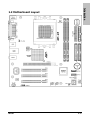
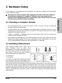
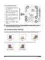
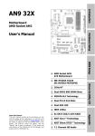
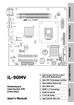
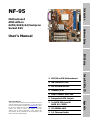
Introduction
NF-95
Hardware Setup
Motherboard
AMD Athlon
64FX/64X2/64/Sempron
Socket 939
User’s Manual
BIOS Setup
NB: NVIDIA C51G
SB: NVIDIA MCP51
2000MT/s HT
Driver & Utility CD
K8 939 mATX Motherboard
Dual Channel DDR 400
Integrated VGA Output
2x SATA 3Gb/s with
RAID 0/1/JBOD
10/100Mb LAN
5.1 Channel Audio
Appendix
About this Manual:
This user’s manual contains all the information you may
need for setting up this motherboard. To view the user’s
manual of PDF format (viewable by Adobe Reader), place
the “Driver & Utility CD” into the CD-ROM drive in your
system. The auto-run screen will appear, click the
“Manual” tab to enter its submenu. If not, browse the
root directory of the CD-ROM via the File Manager, and
double click the “AUTORUN” file.
NF-95
User’s Manual
English, 1st Edition
March 2006
Copyright and Warranty Notice
The information in this document is subject to change without notice and does not represent a
commitment on part of the vendor, who assumes no liability or responsibility for any errors that may
appear in this manual.
No warranty or representation, either expressed or implied, is made with respect to the quality,
accuracy or fitness for any particular part of this document. In no event shall the manufacturer be
liable for direct, indirect, special, incidental or consequential damages arising from any defect or
error in this manual or product.
Product names appearing in this manual are for identification purpose only and trademarks and
product names or brand names appearing in this document are the property of their respective
owners.
This document contains materials protected under International Copyright Laws. All rights reserved.
No part of this manual may be reproduced, transmitted or transcribed without the expressed written
permission of the manufacturer and authors of this manual.
If you do not properly set the motherboard settings, causing the motherboard to malfunction or fail,
we cannot guarantee any responsibility.
ii
NF-95
Introduction
Contents
1. Introduction ..................................................................... 1-1
1.1 Features & Specifications .............................................................1-1
1.2 Motherboard Layout.....................................................................1-3
Hardware Setup
2. Hardware Setup ............................................................... 2-1
2.1 Choosing a Computer Chassis .......................................................2-1
2.2 Installing Motherboard .................................................................2-1
2.3 Checking Jumper Settings ............................................................2-2
2.3.1 CMOS Memory Clearing Header and Backup Battery ..............2-3
BIOS Setup
2.4 Connecting Chassis Components...................................................2-5
2.4.1 ATX Power Connectors ........................................................2-5
2.4.2 Front Panel Switches & Indicators Headers............................2-6
2.4.3 FAN Power Connectors ........................................................2-7
2.4.4 Front Panel Audio Connection Header ...................................2-8
2.5 Installing Hardware......................................................................2-9
2.5.1 CPU Socket 939 ..................................................................2-9
2.5.2 DDR Memory Slots ............................................................ 2-12
2.5.3 Floppy and IDE Disk Drive Connectors ................................ 2-14
2.5.4 PCI Express X16 Add-on Slots ............................................ 2-15
2.5.5 PCI Add-on Slots ............................................................... 2-15
2.5.6 Serial ATA Connectors ....................................................... 2-16
Driver & Utility CD
2.6 Connecting Optional Devices ...................................................... 2-17
2.6.1 Additional USB 2.0 Port Headers......................................... 2-17
2.6.2 Internal Audio Connector ................................................... 2-18
2.7 Connecting I/O Devices.............................................................. 2-19
3. BIOS Setup....................................................................... 3-1
3.1 Standard CMOS Features..............................................................3-2
3.2 Advanced BIOS Features ..............................................................3-5
3.3 Advanced Chipset Features...........................................................3-7
3.4 Integrated Peripherals................................................................ 3-10
3.5 Power Management Setup.......................................................... 3-14
Appendix
3.6 PnP/PCI Configurations .............................................................. 3-17
3.7 PC Health Status........................................................................ 3-18
3.8 Load Fail-Safe Defaults .............................................................. 3-19
NF-95
iii
3.9 Load Optimized Defaults ............................................................ 3-19
3.10 Set Password........................................................................... 3-19
3.11 Save & Exit Setup .................................................................... 3-19
3.12 Exit Without Saving.................................................................. 3-19
4. Driver & Utility CD Support .............................................. 4-1
5. Appendix .......................................................................... 5-1
5.1 Troubleshooting (How to Get Technical Support?) ..........................5-1
5.1.1 Q & A .................................................................................5-1
5.1.2 Technical Support Form ......................................................5-4
5.1.3 ABIT Contact Information ....................................................5-5
iv
NF-95
Introduction
1. Introduction
1.1 Features & Specifications
CPU
• Socket 939 for AMD Athlon64FX, Athlon64X2, Athlon64, or Sempron Processor with
2000MT/s System Bus
• Support AMD Cool ‘n’ Quiet Technology
Chipset
• Northbridge: NVIDIA C51G (GeForce 6100)
• Southbridge: NVIDIA MCP51 (nForce 410)
Memory
• 2X 184-pin DIMM slots support 2GB maximum memory capacity
• Supports Dual Channel DDR 400/333 Un-buffered ECC memory
Graphics
• Integrated NVIDIA GeForce 6100 controller provides enthusiast-class GeForce 6
graphics features
Serial ATA
• 2x SATA 3Gb/s
• Supports SATA RAID 0, 1, JBOD
LAN
• Onboard 10/100Mb PCI controller
Audio
• Onboard 5.1-Channel Audio CODEC
Expansion Slots
• 1x PCI Express x16 slot
• 3x PCI slots
Internal I/O Connectors
•
•
•
•
•
•
1x
2x
2x
2x
1x
1x
floppy disk drive connector
UDMA 133/100/66/33 IDE connectors (each supports 2x IDE devices)
SATA 3Gb/s connectors
USB 2.0 headers (each supports 2x USB 2.0 ports)
FP-Audio header
CD-IN header
Rear Panel I/O
• 1x PS/2 port for mouse
NF-95
1-1
•
•
•
•
•
•
•
1x PS/2 port for keyboard
1x serial port
1x parallel port
1x VGA port
4x USB 2.0 ports
1x RJ-45 LAN port
Audio jacks for line-in, line-out, and microphone
Miscellaneous
• mATX form factor (224mm x 244mm)
※ Specifications and information contained herein are subject to change without
notice.
1-2
NF-95
Introduction
1.2 Motherboard Layout
NF-95
1-3
1-4
NF-95
2. Hardware Setup
In this chapter we will elaborate all the information you need upon installing this motherboard
to your computer system.
※ Always power off the computer and unplug the AC power cord before adding or
removing any peripheral or component. Failing to do so may cause severe
damage to your motherboard and/or peripherals. Plug in the AC power cord only
after you have carefully checked everything.
•
This motherboard carries a mATX form factor of 224 x 244 mm. Choose a chassis big
enough to install this motherboard.
•
As some features for this motherboard are implemented by cabling connectors on the
motherboard to indicators and switches or buttons on the chassis, make sure your chassis
supports all the features required.
•
If there is possibility of adopting some more hard drives, make sure your chassis has
sufficient power and space for them.
•
Most chassis have alternatives for I/O shield located at the rear panel. Make sure the I/O
shield of the chassis matches the I/O port configuration of this motherboard. You can find
an I/O shield specifically designed for this motherboard in its package.
2.2 Installing Motherboard
Most computer chassis have a base with
many mounting holes to allow the
motherboard to be securely attached, and at
the same time, prevent the system from
short circuits. There are two ways to attach
the motherboard to the chassis base:
1. use studs, or
2. use spacers
In principle, the best way to attach the board
is to use studs. Only if you are unable to do
this should you attach the board with spacers.
Line up the holes on the board with the mounting holes on the chassis. If the holes line up and
there are screw holes, you can attach the board with studs. If the holes line up and there are
only slots, you can only attach with spacers. Take the tip of the spacers and insert them into
the slots. After doing this to all the slots, you can slide the board into position aligned with slots.
After the board has been positioned, check to make sure everything is OK before putting the
chassis back on.
NF-95
2-1
Hardware Setup
2.1 Choosing a Computer Chassis
1. Locate all the screw holes on
the motherboard and the
chassis base.
2. Place all the studs or spacers
needed on the chassis base
and have them tightened.
3. Face the motherboard’s I/O
ports toward the chassis’s rear
panel.
4. Line up all the motherboard’s
screw holes with those studs or
spacers on the chassis.
Face the chassis’s rear panel.
To install this motherboard:
5. Install the motherboard with
screws
and
have
them
tightened.
※ To prevent shorting the PCB circuit, please REMOVE the metal studs or spacers if
they are already fastened on the chassis base and are without mounting-holes
on the motherboard to align with.
2.3 Checking Jumper Settings
For a 2-pin jumper, plug the jumper cap on both pins will make it CLOSE (SHORT). Remove the
jumper cap, or plug it on either pin (reserved for future use) will leave it at OPEN position.
SHORT
OPEN
OPEN
For 3-pin jumper, pin 1~2 or pin 2~3 can be shorted by plugging the jumper cap in.
Pin 1~2 SHORT
2-2
Pin 2~3 SHORT
NF-95
2.3.1 CMOS Memory Clearing Header and Backup Battery
The time to clear the CMOS memory occurs when (a) the CMOS data becomes corrupted, (b)
you forgot the supervisor or user password preset in the BIOS menu, (c) you are unable to
boot-up the system because the CPU ratio/clock was incorrectly set in the BIOS menu.
This header uses a jumper cap to clear the CMOS memory and have it reconfigured to the
default values stored in the ROM BIOS.
Pins 1 and 2 shorted (default): Normal operation.
•
Pins 2 and 3 shorted: Clear CMOS memory.
To clear the CMOS memory and load the default values:
1. Power off the system.
2. Set pin 2 and pin 3 shorted by the jumper cap. Wait for a few seconds. Set the jumper cap
back to its default settings --- pin 1 and pin 2 shorted.
3. Power on the system.
4. For incorrect CPU ratio/clock settings in the BIOS, press <Del> key to enter the BIOS setup
menu right after powering on system.
5. Set the CPU operating speed back to its default or an appropriate value.
6. Save and exit the BIOS setup menu.
NF-95
2-3
Hardware Setup
•
CMOS Backup Battery:
An onboard battery saves the CMOS memory to keep the BIOS information stays on even after
disconnected your system with power source. Nevertheless, this backup battery exhausts after
some five years. Once the “CMOS checksum error” message displays on monitor, the battery
is no longer functional and has to be renewed.
To renew the backup battery:
1. Power off the system and disconnect with AC power source.
2. Remove the exhausted battery.
3. Insert a new CR2032 or equivalent battery. Pay attention to its polarity. The “+” side is its
positive polarity.
4. Connect AC power source and power on the system.
5. Enter the BIOS setup menu. Reconfigure the setup parameters if necessary.
CAUTION:
※ Danger of explosion may arise if battery is incorrectly renewed.
※ Renew only with the same or equivalent type recommended by the battery
manufacturer.
※ Dispose of used batteries according to the battery manufacturer’s instructions.
2-4
NF-95
2.4 Connecting Chassis Components
2.4.1 ATX Power Connectors
These connectors provide the connection from an ATX power supply. As the plugs from the
power supply fit in only one orientation, find the correct one and push firmly down into these
connectors.
Hardware Setup
ATX 24-Pin Power Connector:
The power supply with 20-pin or 24-pin cables can both be connected to this 24-pin connector.
Connect from pin-1 for either type. However, a 20-pin power supply may cause the system
unstable or even unbootable for the sake of insufficient electricity. A minimum power of 300W
or higher is recommended.
ATX 12V 4-Pin Power Connector:
This 4-pin 12V power connector mainly supplies power to the CPU. Note that the system will
not start without connecting power to this connector.
NF-95
2-5
2.4.2 Front Panel Switches & Indicators Headers
This header is used for connecting switches and LED indicators on the chassis front panel.
Watch the power LED pin position and orientation. The mark “+” align to the pin in the figure
below stands for positive polarity for the LED connection. Please pay attention to connect these
headers. A wrong orientation will only cause the LED not lighting, but a wrong connection of
the switches could cause system malfunction.
Pin
Definition
Pin
Definition
1
HD LED +
2
MSG LED +
3
HD LED -
4
MSG LED -
5
RESET
6
Power Switch
7
RESET
8
Power Switch
9
Reserved
2-6
NF-95
2.4.3 FAN Power Connectors
These connectors each provide power to the cooling fans installed in your system.
•
CPU_FAN: CPU Fan Power Connector
•
SYS_FAN: System Fan Power Connector
•
PWR_FAN: Auxiliary Fan Power Connector
NF-95
Hardware Setup
※ These fan connectors are not jumpers. DO NOT place jumper caps on these
connectors.
2-7
2.4.4 Front Panel Audio Connection Header
This header provides the auxiliary front-oriented microphone and line-out audio connection for
easier access.
Pin
Signal Name
Function
1
AUD_MIC
Front Panel Microphone input signal
2
AUD_GND
Ground used by Analog Audio Circuits
3
AUD_MIC_BIAS
Microphone Power
4
AUD_VCC
Filtered +5V used by Analog Audio Circuits
5
AUD_F_R
Right Channel audio signal to Front Panel
6
AUD_RET_R
Right Channel Audio signal to Return from Front Panel
7
REVD
Reserved
8
Key
No Pin
9
AUD_F_L
Left Channel Audio signal to Front Panel
10
AUD_RET_L
Left Channel Audio signal to Return from Front Panel
2-8
NF-95
2.5 Installing Hardware
※ DO NOT scratch the motherboard when installing hardware. An accidentally
scratch of a tiny surface-mount component may seriously damage the
motherboard.
2.5.1 CPU Socket 939
DO NOT touch or bend the delicate pins on the CPU whenever you are holding it.
Hardware Setup
1. Pull out the socket lever away from the
socket and fully lift it up over 90-degree
angle.
2. Locate and align the triangle mark with
both the CPU and the socket body.
Vertically place the CPU with its pin-side
down into the socket.
Be careful to insert the CPU into the
socket. The CPU only fits in one
orientation with the socket. DO NOT
force the CPU into the socket.
3. After placing the CPU into position, push
the socket lever down into its locked
position to secure the CPU. The lever
clicks when it’s locked into position.
NF-95
2-9
4. The heatsink for CPU may have thermal
interface material attached to its
bottom. If not, applying a few squeeze
of thermal paste to the CPU die will help
to increase the contact.
5. Place the heatsink and fan assembly
onto the retention frame. Match the
heatsink
clip
with
the
socket
mounting-lug. Hook the spring clip to
the mounting-lug.
Put the CPU Fan down on the retention
module and snap the four retention legs
of the cooling fan into place.
6. On the other side, push the retention
clip straight down to lock into the plastic
lug on the retention frame.
7. Flip the lever over to lock the heat sink
in place.
2-10
NF-95
8. Connect the CPU cooling fan power
cable to the CPUFAN connector on this
motherboard.
※ A higher fan speed will be helpful for better airflow and heat-dissipation.
Nevertheless, stay alert to touch any heatsink since the high temperature
generated by the working system is still possible.
NF-95
2-11
Hardware Setup
※ The installation procedures vary with different types of CPU fan-and-heatsink
assembly. The one shown here is served for demo only. For detailed information
on how to install the one you bought, refer to its installation guidelines.
2.5.2 DDR Memory Slots
This motherboard provides 2x 184-pin un-buffered DDR SDRAM slots for the installation of
single or dual channel DDR400/333 memory modules maximum up to 2GB capacity.
Table 2-1. Unbuffered DIMM Support For AMD 939-pin Processor
Chip Selects
Maximum DRAM Speed
Data Bus
DIMM1
DIMM2
1T
2T
Single Rank
N/A
DDR400
DDR400
Double Rank
N/A
DDR400
DDR400
Single Rank
Single Rank
DDR400
DDR400
Double Rank
Double Rank
DDR400
DDR400
64-bits (Single Channel)
128-bits (Dual Channel)
※ To reach the optimum performance in dual-channel configurations, install DDR
DIMM pairs at the same density, DRAM technology and bus width for both slots.
2-12
NF-95
To install system memory:
1. Power off the computer and unplug the
AC power cord before installing or
removing memory modules.
2. Locate the DIMM slot on the board.
3. Hold two edges of the DIMM module
carefully, keep away of touching its
connectors.
5. Firmly press the module into the slots until the ejector tabs at both sides of the slot
automatically snaps into the mounting notch. Do not force the DIMM module in with extra
force as the DIMM module only fit in one direction.
6. To remove the DIMM modules, push the two ejector tabs on the slot outward
simultaneously, and then pull out the DIMM module.
※ Static electricity can damage the electronic components of the computer or
optional boards. Before starting these procedures, ensure that you are
discharged of static electricity by touching a grounded metal object briefly.
NF-95
2-13
Hardware Setup
4. Align the notch key on the module with
the rib on the slot.
2.5.3 Floppy and IDE Disk Drive Connectors
The FDD connector connects up to two floppy drives with a 34-wire, 2-connector floppy cable.
Connect the single end at the longer length of ribbon cable to the FDD on the board, the two
connectors on the other end to the floppy disk drives connector. Generally you need only one
floppy disk drive in your system.
※ The red line on the ribbon cable must be aligned with pin-1 on both the FDD port
and the floppy connector.
Each of the IDE port connects up to two IDE drives
at Ultra ATA/100 mode by one 40-pin, 80-conductor,
and 3-connector Ultra ATA/66 ribbon cables.
Connect the single end (blue connector) at the
longer length of ribbon cable to the IDE port of this
board, the other two ends (gray and black connector)
at the shorter length of the ribbon cable to the
connectors of your hard drives.
※ Make sure to configure the “Master” and “Slave” relation before connecting two
drives by one single ribbon cable. The red line on the ribbon cable must be
aligned with pin-1 on both the IDE port and the hard-drive connector.
2-14
NF-95
2.5.4 PCI Express X16 Add-on Slots
This slot supports the connection of graphics card that comply with PCI Express specifications.
Hardware Setup
2.5.5 PCI Add-on Slots
These slots provide the connection of add-on cards that comply with PCI specifications.
NF-95
2-15
2.5.6 Serial ATA Connectors
Each SATA connector serves as one single channel to connect one SATA device by a thin SATA
cable.
※ A RAID 0 or RAID 1 disk array configuration is possible through these SATA
connectors, but both the item “On-Chip SATA Controller” and its sub-item “RAID
Mode” in the “IDE Function Setup” BIOS menu has to be set to [Enabled] first.
SATA power cable (optional)
SATA signal cable (optional)
To connect SATA device:
1. Attach either end of the signal cable to
the SATA connector on motherboard.
Attach the other end to SATA device.
2. Attach the SATA power cable to the
SATA device and connect the other end
from the power supply.
To convert between PATA and SATA:
The optional “SERILLEL” is a
convenient accessory to convert
between parallel and serial devices
for this type of motherboard
designed with the SATA controller
from Silicon Image.
2-16
NF-95
2.6 Connecting Optional Devices
2.6.1 Additional USB 2.0 Port Headers
Besides the 4x USB 2.0 ports located at rear I/O part, this motherboard also features 2x more
USB 2.0 headers onboard. Each header supports 2x additional USB 2.0 ports by connecting
bracket or cable to the rear I/O panel or the front-mounted USB ports of your chassis.
Pin Assignment
Pin
Pin Assignment
1
VCC
2
VCC
3
Data0 -
4
Data1 -
5
Data0 +
6
Data1 +
7
Ground
8
Ground
9
NC
10
NC
Make sure the connecting cable bears the same pin assignment.
NF-95
2-17
Hardware Setup
※
Pin
2.6.2 Internal Audio Connector
These connectors connect to the audio output of internal CD-ROM drive or add-on card.
2-18
NF-95
2.7 Connecting I/O Devices
Hardware Setup
•
Mouse: Connects to PS/2 mouse.
•
Keyboard: Connects to PS/2 keyboard.
•
LPT1: Connects to printer or other devices that support this communication protocol.
•
COM1: Connects to external modem, mouse or other devices that support this
communication protocol.
•
VGA1: Connects to monitor input.
•
LAN1: Connects to Local Area Network.
•
USB1/USB2: Connects to USB devices such as scanner, digital speakers, monitor, mouse,
keyboard, hub, digital camera, joystick etc.
•
AUDIO:
Line In: Connects to the line out from external audio sources.
Line Out: Connects to the front left and front right channel in the 5.1-channel or regular
2-channel audio system.
Mic In: Connects to the plug from external microphone.
NF-95
2-19
2-20
NF-95
3. BIOS Setup
This motherboard provides a programmable EEPROM that you can update the BIOS utility. The
BIOS (Basic Input/Output System) is a program that deals with the basic level of
communication between processor and peripherals. Use the BIOS Setup program only when
installing motherboard, reconfiguring system, or prompted to “Run Setup”. This chapter
explains the Setup Utility of BIOS utility.
After powering up the system, the BIOS message appears on the screen, the memory count
begins, and then the following message appears on the screen:
PRESS DEL TO ENTER SETUP
If this message disappears before you respond, restart the system by pressing <Ctrl> + <Alt>
+ <Del> keys, or by pressing the Reset button on computer chassis. Only when it failed by
these two methods can you restart the system by powering it off and then back on.
After pressing <Del> key, the main menu screen appears.
BIOS Setup
※ In order to increase system stability and performance, our engineering staffs are
constantly improving the BIOS menu. The BIOS setup screens and descriptions
illustrated in this manual are for your reference only, and may not completely
match with what you see on your screen.
NF-95
3-1
3.1 Standard CMOS Features
Date (mm:dd:yy)
This item sets the date you specify (usually the current date) in the format of [Month], [Date],
and [Year].
Time (hh:mm:ss)
This item sets the time you specify (usually the current time) in the format of [Hour], [Minute],
and [Second].
IDE Channel 1 Master/Slave, IDE Channel 2 Master/Slave, IDE
Channel 3 Master, IDE Channel 4 Master
Click <Enter> key to enter its submenu:
※ The items “IDE Channel 3 Master” and “IDE Channel 4 Master” appear only when
the item “On-Chip SATA Controller” in the “IDE Function Setup” menu is set to
the default [Enabled] parameter.
3-2
NF-95
IDE HDD Auto-Detection
This item allows you to detect the parameters of IDE drives by pressing <Enter> key. The
parameters will be shown on the screen automatically.
IDE Channel 1 Master/Slave, IDE Channel 2 Master/Slave, Extended IDE Drive
When set to [Auto], the BIOS will automatically check what kind of IDE drive you are using. If
you want to define your own drive by yourself, set it to [Manual] and make sure you fully
understand the meaning of the parameters. Please refer to the instruction manual provided by
the device’s manufacturer to get the setting right.
Access Mode
This item selects the mode to access your IDE devices. Leave this item to its default [Auto]
setting to detect the access mode of your HDD automatically.
Capacity
This item displays the approximate capacity of the disk drive. Usually the size is slightly greater
than the size of a formatted disk given by a disk-checking program.
Cylinder
BIOS Setup
This item configures the numbers of cylinders.
Head
This item configures the numbers of read/write heads.
Precomp
This item displays the number of cylinders at which to change the write timing.
Landing Zone
This item displays the number of cylinders specified as the landing zone for the read/write
heads.
Sector
This item configures the numbers of sectors per track.
Back to Standard CMOS Features Setup Menu
Drive A
This item sets the type of floppy drives (usually only Drive A) installed.
Floppy 3 Mode Support
This item allows you to use “3 Mode Floppy Drive” in Japanese computer systems by selecting
drive A, B, or both. Leave this item to its default [Disabled] setting if you are not using this
Japanese standard floppy drive.
NF-95
3-3
Halt On
This item determines whether the system stops if an error is detected during system boot-up.
[All Errors]: The system-boot will stop whenever the BIOS detect a non-fatal error.
[No Errors]: The system-boot will not stop for any error detected.
[All, But Keyboard]: The system-boot will stop for all errors except a keyboard error.
[All, But Diskette]: The system-boot will stop for all errors except a diskette error.
[All, But Disk/Key]: The system-boot will stop for all errors except a diskette or keyboard
error.
Base Memory
This item displays the amount of base memory installed in the system. The value of the base
memory is typically 640K for system with 640K or more memory size installed on the
motherboard.
Extended Memory
This item displays the amount of extended memory detected during system boot-up.
Total Memory
This item displays the total memory available in the system.
3-4
NF-95
3.2 Advanced BIOS Features
Hard Disk Boot Priority
This item selects the hard disks booting priority. By pressing <Enter> key, you can enter its
submenu where the hard disks detected can be selected for the booting sequence to boot up
system.
This item functions only when there is the option of [Hard Disk] in any one of the
First/Second/Third Boot Device items.
When set to [Enabled], this item speeds up the Power On Self Test (POST) after powering on
the system. The BIOS shorten or skip some check during the POST.
First Boot Device / Second Boot Device / Third Boot Device / Boot Other Device
Select the drive to boot first, second and third in the [First Boot Device], [Second Boot Device],
and [Third Boot Device] items respectively. The BIOS will boot the operating system according
to the sequence of the drive selected. Set [Boot Other Device] to [Enabled] if you wish to boot
from another device other than these three items.
Boot Up Floppy Seek
When set to [Enabled], the BIOS will check whether the floppy disk drive is installed or not.
Boot Up NumLock Status
This item determines the default state of the numeric keypad at system booting up.
[On]: The numeric keypad functions as number keys.
[Off]: The numeric keypad functions as arrow keys.
Security Option
This item determines when the system will prompt for password - every time the system boots
or only when enters the BIOS setup.
NF-95
3-5
BIOS Setup
Quick Power On Self Test
[Setup]: The password is required only when accessing the BIOS Setup.
[System]: The password is required each time the computer boots up.
※ Don’t forget your password. If you forget the password, you will have to open
the computer case and clear all information in the CMOS before you can start up
the system. But by doing this, you will have to reset all previously set options.
Delay For HDD (Secs)
This item allows the BIOS to support some old or special IDE devices by prolonging this delay
time. A larger value will give more delay time to the device for which to initialize and to prepare
for activation.
3-6
NF-95
3.3 Advanced Chipset Features
Onboard GPU
This item enables the onboard GPU function. Disable this item if you are going to install an
external GPU.
Frame Buffer Size
BIOS Setup
This item specifies the Onboard VGA share memory size.
K8<->NB HT Speed
This item sets the speed of HyperTransport between CPU and Northbridge.
NB-->SB HT Speed
This item sets the speed of HyperTransport from Northbridge to Southbridge.
NB<--SB HT Speed
This item sets the speed of HyperTransport from Southbridge to Northbridge.
K8<->NB HT Width
This item sets the HyperTransport width between CPU and Northbridge
NB<->SB HT Width
This item sets the HyperTransport width between Northbridge and Southbridge.
NF-95
3-7
DRAM Configuration
Click <Enter> key to enter its submenu:
DRAM Timing Selectable
This item sets the optimal timings for the following four items, depending on the memory
module you are using. The default setting “By SPD” configures these four items by reading the
contents in the SPD (Serial Presence Detect) device. The EEPROM on the memory module
stores critical parameter information about the module, such as memory type, size, speed,
voltage interface, and module banks.
-
DRAM Clock
This item controls the number of DRAM clocks used for the DRAM parameters.
-
CAS Latency Time
This item controls the latency between the DRAM read command and the time that the data
becomes actually available.
-
Min RAS# Active Time
This item specifies the minimum RAS# active time.
-
RAS# to CAS# Delay
This item controls the latency between the DRAM active command and the read/write
command.
-
RAS# Precharge Time
This item controls the idle clocks after issuing a precharge command to the DRAM.
User Config mode
This item manually sets the DRAM configuration or controlled by BIOS.
-
1T/2T Memory Timing
This item manually specifies the DRAM memory time mode.
-
Read Preamble value
This item manually specifies the DRAM read preamble value.
3-8
NF-95
-
Async Latency value
This item manually specifies the DRAM asynchronous latency value.
BIOS Setup
NF-95
3-9
3.4 Integrated Peripherals
IDE Function Setup
Click <Enter> key to enter its submenu:
On-Chip IDE-1/IDE-2 Controller
This item selects whether to enable or disable the IDE1/IDE2 controller.
On-Chip SATA Controller
This item selects whether to enable or disable the SATA controller.
-
RAID Mode
This item selects whether to enable or disable the RAID controller.
IDE Prefetch Mode:
The onboard IDE drive interfaces supports IDE prefetching for faster drive accesses. If you
install a primary and/or secondary add-in IDE interface, set this field to Disabled if the interface
does not support prefetching.
3-10
NF-95
IDE HDD Block Mode
Block mode is also called block transfer, multiple commands, or multiple sectors read/write. If
your IDE hard drive supports block mode (most new drives do), select Enabled for automatic
detection of the optimal number of block reads/writes per sector the drive can support.
Onboard Device
Click <Enter> key to enter its submenu:
Init Display First
BIOS Setup
This item allows you to choose the primary display card.
On-Chip USB Controller
This option enables or disables the USB controller.
-
USB Keyboard Support via
Select [BIOS] (the default setting) for the legacy operating system (such as DOS) that does
not support USB keyboard.
-
USB Mouse Support via
Select [BIOS] (the default setting) for the legacy operating system (such as DOS) that does
not support USB mouse.
On-Chip Audio Controller
This option enables or disables the audio controller.
Onboard LAN Controller:
This option enables or disables the LAN controller.
-
LAN Boot ROM:
This item allows you to use the boot ROM (instead of a disk drive) to boot-up the system and
access the local area network directly.
NF-95
3-11
SuperIO Device
Click <Enter> key to enter its submenu:
Onboard FDD Controller
This option enables or disables the onboard FDD controller.
Onboard Serial Port
This item determines which I/O addresses the onboard Serial Port controller will access.
[Auto]: The system automatically select an I/O address for the onboard Serial Port.
[3F8/IRQ4, 2F8/IRQ3, 3E8/IRQ4, 2E8/IRQ3]: Allows you to manually select an I/O
address for the onboard Serial Port.
[Disabled]: Disables the onboard Serial Port.
Onboard Parallel Port
This item specifies the I/O address used by the parallel port.
[Disabled]: This option prevents the parallel port from accessing any system resources. When
the value of this option is set to [Disabled], the printer port becomes unavailable.
[378/IRQ7]: This option allows the parallel port to use [378/IRQ7] as its I/O port address.
The majority of parallel ports on computer systems use IRQ7 and I/O Port 378H as the
standard setting.
[278/IRQ5]: This option allows the parallel port to use [278/IRQ5] as its I/O port address.
[3BC/IRQ7]: This option allows the parallel port to use [3BC/IRQ7] as its I/O port address.
-
Parallel Port Mode
This item specifies the parallel port mode.
[SPP]: (Standard Parallel Port) Allows bi-directional parallel port operation at normal speed.
[EPP]: (Enhanced Parallel Port) Allows bi-directional parallel port operation at maximum speed.
[ECP]: (Extended Capabilities Port) Allows bi-directional parallel port operation at a speed
faster than the normal mode’s data transfer rate.
3-12
NF-95
[ECP+EPP]: Allows parallel port operation at ECP and EPP mode.
-
ECP Mode Use DMA
This item selects the DMA channel of the parallel port.
BIOS Setup
NF-95
3-13
3.5 Power Management Setup
ACPI Suspend Type
This item selects the type of Suspend mode.
[S1(POS)]: Enables the Power On Suspend function.
[S3(STR)]: Enables the Suspend to RAM function.
-
Resume by USB From S3
When set to [Enabled], this item allows you to use a USB device to wake up a system that is in
the S3 (STR - Suspend To RAM) state. This item can be configured only if the item “ACPI
Suspend Type” is set to [S3(STR)].
Power Button Function
This item selects the method of powering off your system:
[Delay 4 Sec.]: Pushing the power button for more than 4 seconds will power off the system.
This will prevent the system from powering off in case you accidentally hit or pushed the power
button.
[Instant-Off]: Pressing and then releasing the power button at once will immediately power
off the system.
Power On Function
This item selects the way you want your system to power on.
[Password]: Use a password to power on the system, select this option then press <Enter>.
Enter your password. You can enter up to 5 characters. Type in exactly the same password to
confirm, and then press <Enter>.
[Hot KEY]: Use any of the function keys between <F1> to <F12> to power on the system.
[Mouse Left]: Double click the mouse left button to power on the system.
[Mouse Right]: Double click the mouse right button to power on the system.
[Any KEY]: Use any keyboard keys to power on the system.
3-14
NF-95
[Button Only]: Use only the power button to power on the system.
[Keyboard 98]: Use the power-on button on the “Keyboard 98” compatible keyboard to power
on the system.
※ The mouse wake up function can only be used with the PS/2 mouse, not with
the COM port or USB type. Some PS/2 mice cannot wake up the system because
of compatible problems. If the specs of your keyboard are too old, it may fail to
power on.
-
KB Power ON Password
This item sets the password required in order to power on your computer.
※ Do not forget your password, or you will have to clear the CMOS and reset all
parameters in order to utilize this function again.
-
Hot Key Power ON
This item powers on the system by pressing <Ctrl> key plus one of each function key (<F1> ~
<F12>) simultaneously.
Restore On AC Power Loss
This item selects the system action after an AC power failure.
[Power On]: When power returns after an AC power failure, the system’s power will be
powered on automatically.
[Last State]: When power returns after an AC power failure, the system will return to the
state where you left off before power failure occurs. If the system’s power is off when AC
power failure occurs, it will remain off when power returns. If the system’s power is on when
AC power failure occurs, the system will power-on when power returns.
Wake Up by PCI PME#
When set to [Enabled], access to the onboard LAN or a PCI card such as a modem or LAN card
will cause the system to wake up. The PCI card must support the wake up function.
Wake Up by Ring:
When set to [Enabled], any event affecting from Modem Ring will awaken a system that has
been powered down.
Wake Up by Alarm
When set to [Enabled], you can set the date and time you would like the Soft-Off PC to
power-on in the “Date (of Month) Alarm” and “Time (hh:mm:ss) Alarm” items. However,
if the system is being accessed by incoming calls or the network (Resume On Ring/LAN) prior to
the date and time set in these items, the system will give priority to the incoming calls or
network instead.
NF-95
3-15
BIOS Setup
[Power Off]: When power returns after an AC power failure, the system’s power remains off.
You must press the Power button to power-on the system.
-
Date (of Month) Alarm
[0]: This option power-on the system everyday according to the time set in the “Time
(hh:mm:ss) Alarm” item.
[1-31]: This option selects a date you would like the system to power-on. The system will
power-on on the date set, and the time set in the “Time (hh:mm:ss) Alarm” item.
-
Time (hh:mm:ss) Alarm
This item sets the time you would like the system to power-on.
This item sets the password required in order to power on your computer.
AMD K8 Cool ’n’ Quiet Control:
This item helps the system to lower the frequency when CPU idles. The temperature will drop
automatically when the frequency decreases. Leave this item to its default [Auto] setting and
install the Cool ’n’ Quiet driver.
3-16
NF-95
3.6 PnP/PCI Configurations
Resources Controlled By
This item configures all of the boot and Plug-and-Play compatible devices.
[Auto(ESCD)]: The system will automatically detect the settings.
[Manual]: Choose the specific IRQ resources in the “IRQ Resources” menu.
-
IRQ Resources
BIOS Setup
Click <Enter> key to enter its submenu:
This item sets each system interrupt to either [PCI Device] or [Reserved].
Back to PnP/PCI Configurations Setup Menu
PCI/VGA Palette Snoop
This item determines whether the MPEG ISA/VESA VGA cards can work with PCI/VGA or not.
[Enabled]: MPEG ISA/VESA VGA cards work with PCI/VGA.
[Disabled]: MPEG ISA/VESA VGA cards do not work with PCI/VGA.
Maximum Payload Size
This item sets the maximum TLP payload size for the PCI Express devices.
NF-95
3-17
3.7 PC Health Status
FanEQ Control
This item determines the temperature threshold to raise the fan attached at CPU and SYS fan
headers up to their full speed.
Shutdown Temperature
This item determines the temperature threshold to shut down system.
All Voltages, Fans Speed and Thermal Monitoring
These unchangeable items list the current status of the CPU and environment temperatures, fan
speeds, and system power voltage.
3-18
NF-95
3.8 Load Fail-Safe Defaults
This option loads the BIOS default values for the most stable, minimal-performance system
operations.
3.9 Load Optimized Defaults
This option loads the BIOS default values that are factory settings for optimal-performance
system operations.
3.10 Set Password
This option protects the BIOS configuration or restricts access to the computer itself.
3.11 Save & Exit Setup
This option saves your selections and exits the BIOS setup menu.
BIOS Setup
3.12 Exit Without Saving
This option exits the BIOS setup menu without saving any changes.
NF-95
3-19
3-20
NF-95
4. Driver & Utility CD Support
The “Driver & Utility CD” bundled with this motherboard contains drivers, utilities and software
applications required to set up this motherboard. To enter the auto-run screen of the
installation menu, place the “Driver & Utility CD” into the CD-ROM drive in your system. The
auto-run screen should appear. If not, browse the root directory of the CD-ROM via the File
Manager, and double click the “AUTORUN” file.
[Drivers]: Click on this tab to enter the menu of drivers/utilities installation.
•
[Manual]: Click on this tab to enter the menu of viewing the user’s manual in PDF format.
•
[Utility]: Click on this tab to enter the menu for installing utilities.
•
[ABIT Utility]: Click on this tab to enter the menu for installing utilities exclusively
developed by ABIT.
•
[
Browse CD]: Click on this icon to enter the menu for browsing the contents of
this “Driver & Utility CD”.
•
[
NF-95
Close]: Click on this icon to exit this installation menu.
4-1
Driver & Utility CD
•
4-2
NF-95
5. Appendix
5.1 Troubleshooting (How to Get Technical Support?)
5.1.1 Q & A
Q: Do I need to clear the CMOS before I use a new motherboard to assemble my
new computer system?
A: Yes, we highly recommend that you clear the CMOS before installing a new motherboard.
Please move the CMOS jumper from its default 1-2 position to 2-3 for a few seconds, and
then back. When you boot up your system for the first time, follow the instructions in the
user's manual to load the optimized defaults.
Q: If my system hangs when I update the BIOS or set the wrong CPU parameters,
what should I do?
A: Whenever you update the BIOS or if the system hangs due to wrong CPU parameters
setting, always clear CMOS jumper before booting up again.
Q: Why does the system fail to boot up again right after a mechanical power-off?
A: Please keep a 30-second interval between each mechanical power On/Off.
Q: Why does the system fail to boot up and nothing displays on the screen after I
did some over-clocking or non-standard settings inside the BIOS?
A: It should not cause hardware or permanent damage to motherboard when BIOS settings
were changed from default to over-clocking or non-standard status.
We suggest the following three troubleshooting methods to discharge CMOS data, recover
the hardware default status, and then making the motherboard work again. There is no
need to bother returning the motherboard to where you bought it from or go through an
RMA process.
Step 1.Switch off the power supply unit and then switch it on again after one minute. If
there is no power-switch on the power supply unit, disconnect its power cord for
one minute and then reconnect.
Press and hold the <Insert> key on the keyboard, and press the power-on button
to boot up system. If it works, release the <Insert> key and hit <Del> key to enter
the BIOS setup page to apply the correct settings.
If the situation remains the same, repeat the procedures in Step 1 for three times,
or try Step 2.
Step 2.Switch off the power supply unit or disconnect the power cord. Open the chassis
cover. Locate the CCMOS jumper near the button battery. Change the jumper
position from default 1-2 to 2-3 for one minute to discharge the CMOS data, and
then put it back to default 1-2 position.
NF-95
5-1
Appendix
Close the chassis and switch on the power supply unit or plug in the power cord.
Press the power-on button to boot up system. If it works, hit <Del> key to enter
the BIOS setup page to do the correct settings.
If the situation remains the same, try Step 3.
Step 3.The same procedure as Step 2, but while discharging the CMOS data, pull out the
ATX power connectors from motherboard and remove the button battery during
CMOS discharge.
Q: How to get a quick response for my request on technical support?
A: Please carry out a simple troubleshooting before sending “Technical Support Form”:
System boot-up fails after the system had been assembled:
Check the motherboard’s supporting specifications first to see if all the key components
attached in your system can meet.
To do so, you may:
Remove all the unnecessary add-on devices (except the CPU, VGA card, DRAM, and
Power Supply), and then reboot.
If the trouble still exists, try another VGA card of different brand/model to see if the
system will start.
If the trouble still exists, try another memory module of different brand/model.
If the trouble still exists, try another CPU and Power Supply.
If the system runs successfully, shut it down and start re-installing the interface cards and
devices that were previously installed in the system. Re-install and start the system one at a
time until the system won’t start.
Malfunction in the OS:
If the system hangs after resuming from S3 or some testing program, if the CPU cannot be
recognized properly, if the display resolution mixed, or if a certain program cannot be
executed, etc, you may:
Upgrade the motherboard’s latest BIOS version.
Upgrade the add-on device’s latest driver version.
Check if there is any conflict in the “Control Panel/System Properties”.
Q: How to fill in the “Technical Support Form”?
A: To fill in this “Technical Support Form”, please refer to the following instructions:
5-2
•
Region: Type in your country name.
•
E-mail: Type in your contact E-mail information.
•
First name: Type in your first name.
•
Last name: Type in your last name.
•
Subject: Type in the model name and the problem of your motherboard.
Example 1: AA8XE and SCSI 29160 malfunction
Example 2: AA8XE boot fails, POST code AF
Example 3: AA8XE (system hang when S3 resume)
•
Motherboard: Type in the model name and revision number of your motherboard.
Example: AA8XE REV: 1.00
•
BIOS Version: Type in the BIOS version of your motherboard. (You can find it on the
screen during the POST sequence.)
NF-95
•
CPU: Type in the brand name and the speed (MHz) of your CPU. (Illustrate the
over-clocking status if you had done so.)
Example: Intel 650 3.4GHz (OC FSB=220MHz)
•
Memory brand: Type in the brand and model name of your memory module.
Example: Memory brand: Kingston (KVR533D2N4/1G)
•
Memory size: Type in the size of your memory module.
Example: 512M* 4PCS
•
Memory configuration: Type in the memory configuration in BIOS setting.
Example: Memory Timing: 2.5-3-3-7 @533MHz
•
Graphics information: Note Graphics card’s brand, model and driver version
•
Graphics card: Type in the brand and model name of your graphics card.
Example: ATI RADEON X850 XT PE
•
Graphics driver version: Type in the driver version of your graphics card
Example: Catalyst 5.12V
•
Power supply maker: Type in the brand and model name of your power supply unit.
•
Power supply wattage: Type in the power wattage of your power supply unit.
•
Storage devices: Type in the brand and specifications of your HDD drive and quantity.
Specify if it was inserted on IDE (Master or Slave) or SATA ports, including the RAID
allocation status.
Example 1: WD Caviar WD600 60GB (on IDE2 master), Maxtor DiamondMax 10 SATA
300GB (on SATA 3)
Example 2: Maxtor DiamondMax 10 SATA 300GB *2 (on SATA 3, SATA 4 RAID 1)
•
Optical devices: Type in the brand and specifications of your optical drives and
quantity. Specify if it was inserted on IDE (Master or Slave) or SATA ports.
•
Other devices: Indicate which add-on cards or USB devices that you absolutely sure
are related to the problem. If you cannot identify the problem’s origin, indicate all the
add-on cards or USB devices inserted on your system.
Example: AHA 29160 (on PCI 2), Sandisk Cruzer mini 256MB USB Flash-disk.
•
Operating system: Indicate which OS and language version
Example: Microsoft Windows XP SP2, English version
Example: Microsoft Media Center Edition 2005, Korean version
•
Problem description: Describe the problem of your system configuration. Indicate
the steps to duplicate problem if possible.
See the next page for a blank Technical Support Form, or visit our website to fill in the
form on line (http://www.abit.com.tw/page/en/contact/technical.php).
Q. Is the motherboard dead? Do I need to return it to where I bought from or go
through an RMA process?
A: After you had gone through the troubleshooting procedures, yet the problem still exists, or
you find an evident damage on the motherboard. Please contact our RMA center.
(http://www2.abit.com.tw/page/en/contact/index.php?pFUN_KEY=18000&pTITLE_IMG)
Appendix
NF-95
5-3
5.1.2 Technical Support Form
Country:
First name:
Last Name:
Subject:
Motherboard:
BIOS Version:
CPU:
Memory brand:
Memory size:
Memory configuration:
Graphics card:
Graphics driver version:
Power supply maker:
Power supply wattage:
Storage devices:
Optical devices:
Other devices:
Operating system:
Problem description:
5-4
NF-95
5.1.3 ABIT Contact Information
Taiwan Head Office
ABIT Computer Corporation
No. 323, Yang Guang St., Neihu, Taipei, 114, Taiwan
Tel: 886-2-8751-8888
Fax: 886-2-8751-3382
North America, South America
ABIT Computer (U.S.A.) Corporation
2901 Bayview Drive, Fremont, CA 94538, U.S.A.
Tel: 1-510-623-0500
Fax: 1-510-623-1092
Website: http://www.abit-usa.com
RMA Center: http://rma.abit-usa.com
U.K., Ireland
ABIT Computer (U.K.) Corporation Ltd.
Unit 3, 24-26 Boulton Road, Stevenage, Herts SG1 4QX, U.K.
Tel: 44-1438-228888
Fax: 44-1438-226333
Austria, Czech, Romania, Bulgaria, Slovakia, Croatia, Bosnia, Serbia, Macedonia
Asguard Computer Ges.m.b.H
Schmalbachstrasse 5, A-2201 Gerasdorf / Wien, Austria
Tel: 43-1-7346709
Fax: 43-1-7346713
Germany and Benelux (Belgium, Netherlands, Luxembourg), France, Italy, Spain,
Portugal, Greece, Denmark, Norway, Sweden, Finland, Switzerland
AMOR Computer B.V. (ABIT's European Office)
Jan van Riebeeckweg 15, 5928LG, Venlo, The Netherlands
Tel: 31-77-3204428
Fax: 31-77-3204420
Shanghai
ABIT Computer (Shanghai) Co. Ltd.
Tel: 86-21-6235-1829
Fax: 86-21-6235-1832
Website: http://www.abit.com.cn
Poland
NF-95
Appendix
ABIT Computer (Poland) Co. Ltd.
Przedstawicielstwo w Polsce, ul. Wita Stwosza 28, 50-149 Wrocław
Tel: 48 71 780 78 65 (Technical support/RMA)
Tel: 48 71 718 19 70 (PR/Marketing)
Fax: 48 71 780 78 66
5-5
ABIT Computer Corporation
http://www.abit.com.tw
Rev. 1.00