1
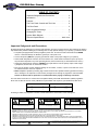
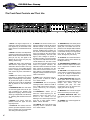
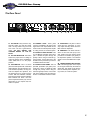
Owners Guide for the
Bass Preamp
INPUT
PAD /
MUTE
GAIN
ULTRA LO /
BRIGHT
DRIVE
BASS
MIDRANGE
FREQUENCY
TREBLE
ULTRA HI /
GRAPHIC EQ
GRAPHIC EQ
+12dB
40
90
180
300
50
1k
MASTER
2k
4k
10k
POWER
+8dB
ACTIVE /
PEAK
-15dB
MUTE
PEAK / MUTE
LO
HI
BRT
EQ
0
-12dB
LEVEL
-10dB
ON
Ampeg ®® is Proudly Made in America
SVP-PRO Bass Preamp
TABLE OF CONTENTS
Important Safeguards and Precautions . . . . . . . . . . . . . . .2
Introduction . . . . . . . . . . . . . . . . . . . . . . . . . . . . . . . . . . . .3
Features . . . . . . . . . . . . . . . . . . . . . . . . . . . . . . . . . . . . . .3
The Front Panel Controls and Their Use . . . . . . . . . . . . . .4
The Rear Panel . . . . . . . . . . . . . . . . . . . . . . . . . . . . . . . . .5
Some Suggested Settings . . . . . . . . . . . . . . . . . . . . . . . . .6
Changing the Tubes . . . . . . . . . . . . . . . . . . . . . . . . . . . . .7
System Block Diagram . . . . . . . . . . . . . . . . . . . . . . . . . . .7
Technical Specifications . . . . . . . . . . . . . . . . . . .back cover
Important Safeguards and Precautions:
All Ampeg products are designed for continuous safe operation, as long as common sense is used and steps are taken to
help avoid certain problems. Abiding by the following rules can help prevent damage to your preamp, yourself and others.
• The preamp is equipped with a three-pronged AC power cord. To reduce the risk of electrical shock, NEVER
remove or otherwise attempt to defeat the ground pin of the power cord.
• Connect the preamp ONLY to a properly grounded AC outlet of the proper voltage for your preamp.
• Avoid sudden temperature extremes, rain and moisture. Also, avoid sudden and intense impact. (If the preamp has been subjected to any of the preceding abuses, have it looked at by an authorized service center.)
• Unplug the preamp before cleaning it. NEVER spray liquid cleaners onto the preamp. Wipe it with a slightly dampened, lint-free cloth to remove dirt and film.
• Don’t use the preamp if it has sustained damage to the chassis, controls, or power cord. Refer the unit to
an authorized service center for inspection.
• NOTE: Amplifiers capable of producing high volume levels are also capable of inflicting permanent hearing
loss or damage, if the exposure to such levels is prolonged. Such damage is progressive and irreversible!
Caution is advised and ear protection is recommended when playing at extremely loud levels.
The chart below shows the U.S. Government Occupational Safety and Health Administration (OSHA) regulations
which were in effect at the time of this publication for permissible noise exposure, per 29CRF1910, Table G-16.
SOUND LEVEL dBA
SLOW RESPONSE
DURATION PER DAY
IN HOURS
SOUND LEVEL dBA
SLOW RESPONSE
DURATION PER DAY
IN HOURS
90
92
95
97
100
8
6
4
3
2
102
105
110
115
1-1/2
1
1/2
1/4 or less
According to OSHA, any exposure in excess of those listed above could result in some hearing loss.
CAUTION
ATTENTION
VORSICHT
RISK OF ELECTRIC SHOCK
DO NOT OPEN
RISQUE D'ELECTROCUTION
NE PAS OUVRIR
ELEKTRISCHE SCHLAGGEFAHR
NICHT OFFENEN
CAUTION: TO REDUCE THE RISK OF ELECTRIC SHOCK,
DO NOT REMOVE COVER.
NO USER-SERVICEABLE PARTS INSIDE.
REFER SERVICING TO QUALIFIED SERVICE PERSONNEL.
ATTENTION: POUR REDUIRE D'ELECTROCUTION NE PAS
ENLEVER LE COUVERCLE. AUCUNE PIECE INTERNE N'EST REPRABLE
PAR L'UTILISATEUR. POUR TOUTE REPARATION, S'ADRESSER A UN
TECHNICIEN QUALIFIE.
VORSICHT: ZUR MINIMIERUNG ELEKTRISCHER SCHLAGGEFAHR NICHT
DEN DECKEL ABENHMEN. INTERNE TEILE KONNEN NICHT VOM
BENUTZER GEWARTET WERDEN. DIE WARTUNG IS QUALIFIZIERTEM
WARTUNGSPERSONAL ZU UBERLASSEN.
THIS EQUIPMENT HAS BEEN DESIGNED AND ENGINEERED TO PROVIDE SAFE AND RELIABLE OPERATION. IN ORDER TO PROLONG THE LIFE OF THE
UNIT AND PREVENT ACCIDENTAL DAMAGES OR INJURY, PLEASE FOLLOW THESE PRECAUTIONARY GUIDELINES:
WARNING: TO REDUCE THE RISK OF ELECTRIC SHOCK, DO NOT OPEN CHASSIS; DO NOT DEFEAT OR REMOVE THE GROUND PIN OF THE POWER
CORD; CONNECT ONLY TO A PROPERLY GROUNDED AC POWER OUTLET.
CAUTION: TO REDUCE THE RISK OF FIRE OR ELECTRIC SHOCK, DO NOT EXPOSE THIS EQUIPMENT TO RAIN OR MOISTURE.
CAUTION: NO USER-SERVICEABLE PARTS INSIDE. REFER SERVICING TO QUALIFIED SERVICE PERSONNEL.
CAUTION: OUR AMPLIFIERS ARE CAPABLE OF PRODUCING HIGH SOUND PRESSURE LEVELS. CONTINUED EXPOSURE TO HIGH SOUND PRESSURE
LEVELS CAN CAUSE PERMANENT HEARING IMPAIRMENT OR LOSS. USER CAUTION IS ADVISED AND EAR PROTECTION IS RECOMMENDED IF UNIT IS
OPERATED AT HIGH VOLUME.
EXPLANATION OF
GRAPHICAL SYMBOLS:
2
"DANGEROUS VOLTAGE"
= "DANGER HAUTE TENSION"
"GEFAHLICHE SPANNUNG"
"IT IS NECESSARY FOR THE USER TO REFER TO THE INSTRUCTION MANUAL"
= "REFERREZ-VOUS AU MANUAL D'UTILISATION"
"UNBEDINGT IN DER BEDIENUNGSANLEITUNG NACHSCHLAGEN"
SVP-PRO Bass Preamp
An Introduction to your new Ampeg SVP-PRO Bass Preamp
The harmonically rich sound and legendary performance of the AMPEG SVT are redefined in
the SVP-PRO. This dynamic preamp delivers unsurpassed quality, reliability and tonal flexibility
and offers the classic vibrancy of tubes. The SVP-PRO is the preamp section of our muchrespected SVT-2 PRO. All of the features and controls of your SVP-PRO are covered in detail in
this owner’s guide. We recommend that you read it before you use the preamp.
Features
In the world of high performance bass amps, Ampeg’s SVT amplifiers stand alone. Keeping
with true Ampeg tradition, the SVP-PRO Bass Preamp offers you more performance and flexibility than any other preamp in its class. Listed below are some of the outstanding features of
your new preamp - features which set it apart from the competition! Additional information on
these features can be found on the pages indicated.
• PAD: A switchable input pad, this feature is perfect for basses with active electronics or very “hot” pickups (page 4)
• MUTE SWITCH: Allows you to tune your bass in private (page 4)
• ULTRA LOW, ULTRA HIGH AND BRIGHT SWITCHES: Lets you tailor the sound
to suit your tastes “with the touch of a button” (page 4)
• 5-POSITION MIDRANGE SELECTOR: Five center frequency points are available
to get just the right midrange voice (page 4)
• 9-BAND GRAPHIC EQ: Shapes the sound to your own exacting standards (or use it
as a “second channel” for bass solos). An independent level control lets you adjust
the Graphic EQ volume. Switchable at front panel or with a footswitch (page 4)
• TRANSFORMER BALANCED OUT: Electrically isolate your system from the PA or
recording mixer to eliminate ground loop hum
3
SVP-PRO Bass Preamp
The Front Panel Controls and Their Use
INPUT
PAD /
MUTE
ULTRA LO /
BRIGHT
GAIN
DRIVE
BASS
MIDRANGE
FREQUENCY
TREBLE
ULTRA HI /
GRAPHIC EQ
GRAPHIC EQ
+12dB
40
90
180
300
50
1k
MASTER
2k
4k
10k
POWER
+8dB
ACTIVE /
PEAK
-15dB
MUTE
1
2 3
PEAK / MUTE
4
5
LO
HI
BRT
EQ
6 7
8
9
1. INPUT: The signal output from an
instrument (active or passive) or a line
level signal may be connected to this
jack by means of a shielded instrument
cable.
2. MUTE: This switch, when depressed,
mutes the signal at the the Preamp Out,
Effects Send and Transformer Bal. Out
jacks (24, 26, 29). The signal is not
affected at the Tuner Out jack (27),
allowing “silent tuning.”
3. PAD: This switch, when depressed,
attenuates the input signal by 15dB.
Attenuation allows the Gain control (4)
to be used in a more usable (higher)
position. If clipping is indicated with the
Gain control way down, attenuation is
needed.
4. GAIN: This control, along with the
Pad switch (3), adjusts the level of the
signal at the beginning of the preamp.
To get the best signal to noise ratio,
adjust this control until the Peak/Mute
LED (5) flashes on the loudest passages.
5. PEAK/MUTE LED: This LED flashes when the signal level into the preamp (excluding the Graphic EQ)
approaches clipping. When the Mute
switch (2) is depressed, this LED stays
on, indicating that the Mute function is
active.
6. BRIGHT: This switch, when depressed, boosts the upper mid and
high frequencies.
7. ULTRA LO: This switch, when depressed, provides emphasis to the low
end by boosting the low frequencies
and cutting the mid frequencies.
4
10
11
12
0
LEVEL
-12dB
1314
8. DRIVE: This control is used to overdrive the preamp in order to get various
distortion sounds. In the fully counterclockwise position the preamp is in the
cleanest, traditional SVT condition. As
the control is rotated clockwise, signal
level is increased to drive the preamp
harder (into distortion). The tone of the
signal is also changed to provide a
smoother overdrive. The tone controls
may have to be readjusted to obtain the
overall desired tone. The Gain control
(4) and Pad (3) interact with the Drive
control. For greater overdrive, the
attenuator switch should be out and the
Drive control full clockwise. Use the
Gain control to set the amount of overdrive desired. The Peak/Mute LED (5)
will glow a steady red when the amp is
used in this manner.
9. BASS: This is the primary low frequency control. It allows for 12dB of
cut or boost at 40Hz.
10. MIDRANGE: This is the primary
midrange control. It allows for 15dB of
cut or 12dB of boost at the center frequency selected by the Frequency
control (11).
11. FREQUENCY: Allows you to
select the center frequency for the
Midrange control (10), giving you a
choice of five “voices” for the
Midrange. The center frequencies are
(from left to right) 220Hz, 450Hz,
800Hz, 1.6kHz, and 3kHz.
12. TREBLE: This is the primary high
frequency control. It allows for 12dB
cut or boost at 4kHz.
-10dB
15
16 17
ON
18
19
20
13. GRAPHIC EQ: This switch places
the Graphic EQ circuitry in or out of the
signal path. The switch must be depressed for the Graphic EQ footswitch
to function. In the OUT position, there is
no solid state circuitry in the signal path
from input to preamp out (in other
words, the signal is “pure tubes”).
14. ULTRA HI: This switch boosts the
frequencies above those affected by
the Bright switch (6).
15. EQ FREQUENCY SLIDERS: These
sliders control the Graphic EQ section
at the frequencies indicated above
each slider.
16. EQ LEVEL: This adjusts the level
of the signal to compensate for boosts
or cuts, or to obtain a desired level
change when using the Graphic EQ.
17. EQ ACTIVE/PEAK LED: This LED
glows yellow when the EQ section is
enabled by the proper combination of
Graphic EQ switch (13) and
Footswitch jack (23). The LED
momentarily turns off whenever the
signal gets close to clipping.
18. MASTER: This controls the signal
level to the Preamp Out Jacks (24).
19. POWER INDICATOR LED: This
LED glows green when the preamp is
on.
20. POWER: This switch supplies AC
power to the unit.
SVP-PRO Bass Preamp
The Rear Panel
FOOT
SWITCH
PREAMP OUT
EFFECTS
TUNER
OUT
TRANSFORMER BAL. OUT
PRE
MADE IN THE U.S.A. BY
SLM ELECTRONICS
1400 FERGUSON AVENUE
ST. LOUIS, MO 63133
AC LINE IN
21
115V
230V
22
21. AC LINE IN: Firmly insert the supplied AC power cord into this socket
until it is fully seated. Plug the male
end of the cord into a grounded AC
outlet. DO NOT DEFEAT THE
GROUND PRONG OF THE AC
PLUG!
22. AC LINE SELECTOR: This switch
selects the proper AC line voltage to
match the preamp to the available AC
mains. Make sure it is in the proper
position.
23. FOOTSWITCH: This is a stereo
jack which will operate with a standard
dual footswitch. The tip of the plug controls the Mute operation, the ring controls the Graphic EQ operation, and
the sleeve acts as a ground common
to both. With the footswitch inserted,
both the front panel and the footswitch
Mute switches are active. The front
panel Graphic EQ switch (13) must be
depressed for the Graphic EQ footswitch to operate.
MODEL #
SVP PRO
SERIAL #
2556A
23
24
24. PREAMP OUTS: These jacks
carry the post-Master (18) signal. This
signal is the main output which can be
used to feed an external power amplifier, mixing console, or house PA system.
25. EFFECTS LOOP RETURN: This
is a pre-Master (18) patch point return
jack. It breaks the path through the
preamp. When using an external signal processor, connect this jack to the
OUTPUT of the processor by means of
a shielded instrument cable.
26. EFFECTS LOOP SEND: This is a
post-EQ, pre-Master (18) patch point
send jack. It does not break the path
through the preamp. When using an
external signal processor, connect this
jack to the INPUT of the processor by
means of a shielded instrument cable.
RETURN
SEND
25
26
POST
27
28
29
27. TUNER OUT: This jack is a direct
output from the instrument. It is the
only output that stays active when the
Mute switch is depressed.
28. PRE/POST: This switch selects a
direct out from the bass (Pre) in the
OUT position and the preamp signal
just before the Master (18) (Post) in
the depressed position. The selected
signal is sent to the Balanced Out jack
(29).
29. TRANSFORMER-BALANCED
OUT: This XLR-type jack is the output
for the signal selected by the Pre/Post
switch (28). This signal can be used to
feed an external power amplifier, mixing console, or house PA system.
5
SVP-PRO Bass Preamp
Some Suggested Settings*
JAZZ:
GAIN
ULTRA LO /
BRIGHT
PEAK / MUTE
DRIVE
BASS
MIDRANGE
FREQUENCY
TREBLE
ULTRA HI /
GRAPHIC EQ
IN
OUT
LO
HI
OUT
OUT
BRT
EQ
ADJUST UNTIL PEAK LED FLASHES
FUNK:
GAIN
ULTRA LO /
BRIGHT
DRIVE
BASS
MIDRANGE
FREQUENCY
TREBLE
IN
IN
OUT
OUT
BRT
EQ
LO
PEAK / MUTE
ULTRA HI /
GRAPHIC EQ
HI
ADJUST UNTIL PEAK LED FLASHES
ROCK:
GAIN
ULTRA LO /
BRIGHT
PEAK / MUTE
DRIVE
BASS
MIDRANGE
FREQUENCY
TREBLE
ULTRA HI /
GRAPHIC EQ
OUT
OUT
LO
HI
IN
OUT
BRT
EQ
ADJUST UNTIL PEAK LED FLASHES
COUNTRY:
GAIN
ULTRA LO /
BRIGHT
PEAK / MUTE
DRIVE
BASS
MIDRANGE
FREQUENCY
ULTRA HI /
GRAPHIC EQ
IN
OUT
LO
HI
OUT
OUT
BRT
EQ
ADJUST UNTIL PEAK LED FLASHES
*A Note About The Graphic EQ:
The Graphic EQ can be used in two ways:
1) To fine tune your sound, make small adjustments at the
desired frequencies and leave the EQ on throughout the
entire session. (This is great for adapting to varying room
acoustics when going from club to club, etc.);
2) For a completely different sound, make larger adjustments
and only activate the EQ when you want a “second channel”
sound (such as during bass solos).
6
TREBLE
SVP-PRO Bass Preamp
Changing the Tubes
The performance characteristics of tubes are degraded in direct proportion to how often and under what conditions the
amplifier is used. Preamp tubes typically last longer than power tubes. When a preamp tube wears out, the preamp may
squeal, get noisy, lose gain and sensitivity, or just quit working. A service center can determine which tube(s) may need
replacing. To gain access to the tubes in the SVP-PRO, the top must be removed. Tube replacement should only be
performed by a qualified service person.
System Block Diagram
BUFFER
TUNER
OUT
PEAK
LED
INPUT
-15dB PAD
GAIN
BRIGHT
ULTRA
LO
ULTRA
HI
DRIVE
BASS TREBLE
MID
FREQUENCY
PRE/POST
MUTE
TRANSFORMER
BALANCED
OUT
EQ ON
EFFECTS EFFECTS
SEND
RETURN
PREAMP
OUT
GRAPHIC
EQ
MASTER
BUFFER
PREAMP
OUT
LEVEL
MUTE
SWITCHING
CIRCUIT
FOOTSWITCH
GRAPHIC
EQ
7
SVP-PRO Bass Preamp
Technical Specifications
TOTAL SYSTEM GAIN
TONE CONTROL RANGE
Bass:
Midrange:
Treble:
Ultra Low:
Ultra High:
Bright:
GRAPHIC EQ RANGE
GRAPHIC EQ LEVEL
SIGNAL TO NOISE RATIO
TUBE COMPLEMENT
POWER REQUIREMENTS
Domestic:
Export:
SIZE AND WEIGHT
76dB, @1kHz w/levels up, tones flat; -3dB @30Hz, 15kHz
±12dB @ 40Hz
+12dB, -15dB @ Frequency selected (220, 450, 800, 1.6k or 3kHz)
±12dB @ 4kHz
+3dB @ 40Hz, -12dB @ 500Hz
+8dB @ 8kHz
+7dB @ 2kHz
±12dB @ 40Hz, 90Hz, 180Hz, 300Hz, 500Hz, 1kHz, 2kHz, 4kHz, 10kHz
+8dB, -10dB
80dB typical
12AX7 (4), 12AU7 (1)
120VAC, 60Hz, 28VA
100/115VAC 50/60Hz, 28VA
230VAC, 50/60Hz, 28VA
19”W x 1.75”H x 10”D; 9 lbs
Ampeg reserves the right to change specifications without notice.
www.ampeg.com
Ampeg is proudly Made in America
©1999 SLM Electronics
1400 Ferguson Avenue
St. Louis, MO 63133 U.S.A.
P/N 47-546-13 • 05/99