1
LP 100R Laser Printer
Installation Guide
Part No. 9855148
Revision number
Date
Reason for update
Rev 0
March, 2009
Initial release
Rev 1
April, 2014
USB Support, Company Info
Copyright © 2009 SATO America, Inc.
ALL RIGHTS RESERVED
No part of this work may be reproduced or copied in any form without the express
written consent of:
SATO America, Inc.
1140 Windham Pkwy.
Romeoville, IL 60446
Notice
All rights are reserved for devices, circuits, techniques, software, and names
appearing in this publication.
SATO America, Inc. ("SATO"), also reserves the right to make changes to this
publication and to the equipment described herein without notice.
Considerable effort has been made to ensure that this publication is free of
inaccuracies and omissions. SATO, however, makes no warranty of any kind
including, but not limited to, any implied warranties of merchantability and fitness for a
particular purpose with regard to this publication.
This publication is in conformance with international standards and guidelines valid at
the date of printing.
Trademarks
METO® is a registered trademark of SATO.
Kodescript™ and KodescriptPlus™ are trademarks of SATO.
HP®, Hewlett-Packard®, and PCL® are registered trademarks of Hewlett-Packard
Company.
Intel® is a registered trademark of Intel Corporation.
PostScript® is a registered trademark of Adobe Systems Incorporated.
TrueType™ is a trademark of Apple Computer, Inc.
Copyright © 2009 by SATO America, Inc.
All rights are reserved. This publication may not be copied in whole or in part, nor
transferred to any other media or language without the express written permission of
SATO America, Inc.
Liability Disclaimer
SATO America, Inc., products are warranted in accordance with the terms of the
applicable SATO product specification. Product performance is affected by system
configuration, software, the application, customer data, and operator control of the
system, among other factors. While SATO products are compatible with the
standards for which they are advertised, implementation by customers of the product
may vary. The suitability of a product for a specific application, therefore, must be
determined by the customer and is not warranted by SATO.
This manual is as complete and factual as possible at the time of printing; however,
the information in this manual may have been updated since that time. SATO
reserves the right to change the functions, features, or specifications of its products at
any time, without notice.
SATO America, Inc., has prepared this manual for use by SATO employees and
customers. The information contained herein is the property of SATO and must not be
reproduced without prior written approval from SATO.
MSDS sheets are available by request.
INSTALLATION GUIDE
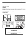
Regulatory Notices
Laser Safety
This product employs a Class 3B laser diode having maximum power of 35 mW and wavelength of 770-800 nm.
This product is certified as a Class 1 laser product. Since the laser beam is concealed by protective housings, the
product does not emit hazardous laser radiation as long as the product is operated according to the instructions in
this manual.
Internal Laser Radiation
Maximum average radiation power: 22 μW at the PC Drum
Wavelength: 770-800 nm
Complies with 21 CFR 1040.10 and 1040.11
except for deviations pursuant to laser notice
No.50, dated June 24, 2007
Or/and
! DANGER
Use of controls or adjustments or performance of procedures
other than those specified in this manual may result in
hazardous radiation exposure.
III
INSTALLATION GUIDE
FCC Regulations
This equipment generates and uses radio frequency and, if not installed in accordance with the instruction manual,
may cause interference to radio and television reception. The equipment has been tested and found to comply
within the limits for a Class A computing device in accordance with specifications in subpart J of Part 15 of the
Federal Communication Commission (FCC) Rules, which are designed to provide reasonable protection against
such interference in a commercial installation.
Note: Use a shielded and properly grounded I/O cable to ensure that this unit complies to the limits specified in the
FCC Rules.
There is no guarantee, however, that interference will not occur in a particular installation. If this equipment does
cause harmful interference to radio or television reception, which can be determined by turning the equipment off
and on, the user, at his or her own expense, will be required to take whatever measures may be necessary to
correct the interference.
For more information on preventing radio frequency interference, see the Manufacturer’s Instructions and User’s
Responsibility sections that follow.
IV
INSTALLATION GUIDE
Manufacturer’s Instructions
The user must observe the following precautions in installing and operating this device:
1. Operate the equipment in strict accordance with the manufacturer’s instructions for the model.
2. Plug the printer into a properly grounded wall outlet and use, unmodified, the power cord supplied with the unit.
3. Always operate the printer with all factory-installed covers on the unit.
4. Make no modification to the equipment that would affect its meeting the specified limits of the FCC Rules.
5. Maintain the equipment in a satisfactory state of repair.
6. Use a shielded and properly grounded I/O cable to ensure compliance of this unit to the specified limits of the
FCC Rules.
User’s Responsibility
The user is ultimately responsible for correcting problems arising from harmful radio frequency emissions from
equipment under his or her control. If this equipment does cause interference to radio or television reception
(which as specified can be determined by turning the printer off and on), SATO encourages the user to try to
correct the interference by changing one of the following:
•
Equipment orientation
•
Equipment location
•
Power source
All of these responsibilities and any others not mentioned are exclusively at the user's expense.
If necessary, the user should consult SATO for additional suggestions.
Note: If it is determined that equipment operation is causing harmful interference, the equipment operator may be
required to stop operating the equipment until the interference problem is corrected.
V
INSTALLATION GUIDE
DHHS
This printer is certified as a Class 1 Laser Product under the United States Department of Health and Human
Services (DHHS) Radiation Standard according to the Radiation Control for Health and Safety Act of 1968. This
means that the printer does not produce hazardous laser radiation.
Since radiation emitted inside the printer is wholly confined within protected housings and external covers, the
laser beam cannot escape from the equipment during any phase of user operation.
CDRH Regulations
The Center of Devices and Radiological Health (CDRH) of the United States Food and Drug Administration
implemented regulations for laser products on August 2, 1976. These regulations apply to laser products
manufactured from August 1, 1976. Compliance is mandatory for laser products marketed in the United States.
The following statement, which indicates compliance with the CDRH regulations, must be affixed to the laser
products marketed in the United States:
THIS PRODUCT CONFORMS WITH CDRH
RADIATION PERFORMANCE STANDARD
TITLE 21 CFR CHAPTER 1, SUBCHAPTER J
VI
INSTALLATION GUIDE
General Notes, Warnings, and Cautions
Note: The LP 100R printer uses an electrophotographic printing system, which requires more precautions in
observing paper specifications than those required for conventional impact line printers. In an electrophotographic
printing system, improper toner transfer and missing characters are evident if the paper absorbs moisture and
ripples in the vicinity of the perforation.
Note: When paper is stored in unfavorable conditions or does not meet the specifications cited in the
LP 100R Operator's Guide, print quality, as well as feeding and fusing functions, will suffer.
! WARNING
Paper not within specifications may cause physical damage to the LP 100R
printer and jeopardize printer performance (leading to the creation of waste
and a consequent loss of production).
SATO advises that the printer be connected to a power source that has an
isolated, dedicated ground to prevent interference from other equipment
(which may cause printer memory loss during operation).
! CAUTION
Before gaining access to any internal parts of the printer, always remove
power from the unit by unplugging the AC power cord.
This manual must be reviewed and understood
before performing any service on the LP 100R printer.
VII
INSTALLATION GUIDE
Preface
Purpose of This Guide
To present installation instructions for the LP 100R printer. This guide provides all installation instructions, from
initial unpacking through electromechanical setup, that are required to prepare the printer for paper loading and
operation using the instructions provided in the LP 100R Operator's Guide (Document Number 9855063).
How to Use This Guide
Start with paragraph 1.1 and follow the instructions provided. Note that the order in which groups of instructions
are performed can change due to such variables as the printer location when unboxed and the width of the door
openings through which it must be moved.
VIII
INSTALLATION GUIDE
TABLE OF CONTENTS
CHAPTER 1. PRELIMINARY INSTRUCTIONS ...................................... 1
1.1
Operating Location Requirements ........................................ 1
1.2
Unboxing and Unpacking Instructions .................................. 1
1.3
Before Moving the Printer to the Operating Location............ 1
1.4
Door Opening Minimum Width Requirements....................... 1
CHAPTER 2. UNPACKING INSTRUCTIONS .......................................... 2
2.1
Removing the Carton ............................................................ 2
2.2
Removal of Packing Material and Accessories Boxes .......... 4
CHAPTER 3. MOVING THE PRINTER TO THE OPERATING
LOCATION.......................................................................................... 9
3.1
General Cautions ................................................................... 9
3.2
After Moving ........................................................................... 9
CHAPTER 4. UNPACKING AND INVENTORY OF ACCESSORIES
BOXES ............................................................................................ 10
4.1
Accessories Box No. 1 ......................................................... 10
4.2
Accessories Box No. 2 ......................................................... 11
4.3
Accessories Box No. 3 ......................................................... 11
4.4
Missing or Damaged Accessories ........................................ 11
i
INSTALLATION GUIDE
TABLE OF CONTENTS, continued
4.5
Installation of the Suction Brake Unit ................................... 12
4.6
Installation of Web Guide/Connector Panel ......................... 13
CHAPTER 5. ELECTRO MECHANICAL SETUP PROCEDURE........... 15
ii
5.1
Mounting the Paper Stopper (Stacker)................................ 15
5.2
Preparation of the Developer Unit....................................... 16
5.3
Controller Installation, Meto-Logic ...................................... 21
5.4
Storage of Test Print Samples............................................. 24
5.5
Power Cord Connection...................................................... 27
5.6
Main Power-On ................................................................... 29
5.7
Controller Power-On ........................................................... 29
5.8
Entering Maintenance Mode ............................................... 30
5.9
ATDC Adjustment ............................................................... 32
5.10
Toner Bottle Installation....................................................... 33
5.11
Power Off ............................................................................ 35
5.12
Final Mechanical Check...................................................... 36
5.13
Leveling the Printer ............................................................. 36
INSTALLATION GUIDE
TABLE OF CONTENTS, continued
CHAPTER 6. EQUIPMENT SPECIFICATION ....................................... 37
CHAPTER 7. EQUIPMENT INSTALLATION CHECKLIST
PREPARATION ................................................................................ 37
CHAPTER 8. PAPER LOADING AND PRINTING TEST AND
STATUS PAGE ................................................................................. 37
Appendix A
LP 100R Printer Operating Location Requirements
Appendix B
LP 100R European Power Considerations
Appendix C
LP 100R Printer Equipment Specifications
Appendix D
LP 100R Swing Guide Installation (Optional)
Appendix E
LP 100R Burster Unit Installation (Optional)
Appendix F
LP 100R IPDS USB Key Installation (Optional)
Appendix G
LP 100R PC Cartridge Installation
Appendix H
LP 100R Printer Equipment Installation Checklist
iii
INSTALLATION GUIDE
This page is intentionally blank.
iv
INSTALLATION GUIDE
CHAPTER 1. Preliminary Instructions
1.1
Operating Location Requirements
1. Refer to Appendix A, “LP 100R Printer Operation Location Requirements” and perform the steps
provided to determine if all requirements have been met.
2. If the operating location requirements have been met, proceed to paragraph 2.1.
1.2
Unboxing and Unpacking Instructions
1.
If the printer has not been unboxed, refer to paragraph 2.2, "Removal of Packing Material and
Accessories Boxes” and perform the provided steps.
2.
If the printer controller has already been unboxed, proceed to paragraph 5.3, “Controller Installation,
Meto-Logic.”
In the event that the printer was already located in its operating location when unboxed, SKIP
paragraph 2.2 “Removal of Packing Material and Accessories Boxes” and proceed as
instructed.
1.3
Before Moving the Printer to the Operating Location
1.
1.4
Before moving the printer to its operating location, measure the width of the door opening. Proceed to
paragraph 3.1.
Door Opening Minimum Width Requirements
When moving an “out of box” LP 100R printer through a door opening, ensure that door openings are
no smaller than the required minimum width of 35” (889 mm).
1
1.
Measure all door openings through which the printer must pass to reach its operating location.
2.
To move a printer that has been existing in an operating location, remove the Suction Brake Unit from
the printer. Refer to paragraph 4.5, "Installation of the Suction Brake Unit."
INSTALLATION GUIDE
CHAPTER 2. Unpacking Instructions
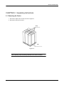
2.1 Removing the Carton
1. Remove the straps from the carton as shown in Figure 2-1.
2. Remove the nails from the carton.
Strap
Nail
Figure 2-1
After unpacking, keep all packing materials out of reach of children.
2
INSTALLATION GUIDE
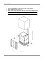
3. Lift the outer carton as shown in Figure 2-2 until the carton is clear of the printer.
4. Remove the ramp on the side of the printer.
5. Remove the four cushions under the printer and remove the plastic bag surrounding the printer.
Use caution when handling the ramp.
Ramp
Figure 2-2
3
INSTALLATION GUIDE
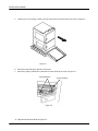
2.2
Removal of Packing Material and Accessories Boxes
1. Remove the two accessories boxes from the stacker tray.
2. Raise the stacker table upward.
3. Insert the ramp into the pallet on the front of the printer as shown in Figure 2-3.
Make sure that the ramp cannot separate from the pallet.
Ramp
Figure 2-3
4. Adjust the printers leveling feet (4) upward from the base plate. Allow a minimum of 20mm of
clearance for the printer to move unobstructed down the ramp. (See Figure 2-4)
Figure 2-4
4
INSTALLATION GUIDE
5.
Utilizing four or more people, carefully move the printer down the ramp to the floor as shown in Figure 2-5.
Figure 2-5
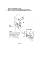
6. Remove the tape holding the right side of the printer.
7. Remove the packing material from underneath the tractor assembly as shown in Figure 2-6.
Packing Material
Tractor Assembly
Figure 2-6
8. Open the left door as shown in Figure 2-7.
5
INSTALLATION GUIDE
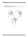
9.
10.
11.
12.
Open the fuser lamp assembly (2) screws.
Remove the shipping cushion on the fuser glass as shown in Figure 2-7.
Remove the tape holding the Fuser Toner Filter and Exit Rollers (Figure 2-7).
Remove any remaining tape and packing material from the outside of the printer.
Tape,
Cushion
Fusing Toner Filter
Fusing Unit
Suction Brake Unit Box
Figure 2-7
6
INSTALLATION GUIDE
13.
14.
15.
16.
Open the front door.
Remove all visible tape as shown in Figure 2-8 below.
Remove the Toner Collecting Bottle and then remove the tape from the lower charger unit.
Re-install the Toner Collecting Bottle.
Tape
Toner Collecting Bottle
Tape
Tape
Figure 2-8
7
INSTALLATION GUIDE
17.
18.
19.
20.
21.
Remove the Lower Right Side Cover.
Remove the Controller and remove packing material around the controller.
Remove the Controller cover and confirm that all boards are securely seated.
Replace the Cover.
Unwrap the Printer Power Cord, Controller Power Cord, and the AC adapter, all located in the lower
printer compartment.
Printer Power Cord
Controller Power Cord
AC Adapter
Controller
Figure 2-9
!
WARNING
!
Before installation, the Controller power supply voltage selector switch
must be set to the 230V position.
22. Refer to paragraph 5.3 for complete Controller Installation.
8
INSTALLATION GUIDE
CHAPTER 3. Moving the Printer to the Operating Location
3.1
General Cautions
1. Use care not to damage the finish of the printer covers, especially while moving the printer through
door openings.
2. Do not tilt the printer more than 0.5 degree.
3. Do not drop the printer from a height exceeding 3 cm.
4. If the printer is moved on a “dolly,” make certain that it is entirely stable before moving.
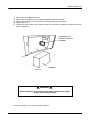
5. If the printer is to be moved with a “fork lift,” use only the fork insertion position shown in Figure 3-1.
FORK INSERTION POSITION
Suction Brake
Fork Lift
Insertion Point
3.2
Figure 3-1
After Moving
1. If no parts were removed for moving, proceed to paragraph 4.1, step 1.
2. If printer parts were removed for moving, replace all of the parts at this time.
9
INSTALLATION GUIDE
CHAPTER 4. Unpacking and Inventory of Accessories Boxes
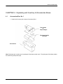
4.1
Accessories Box No. 1
1. Unpack and inventory the contents of accessory Box 1.
Toner Bottle
&
Paper Stopper
Developer Powder
(2) Packs
Accessories
Note: Developer pack contains two (2) packages of developer powder each. Two packages of developer powder
are used during initial printer prep.
10
INSTALLATION GUIDE
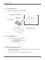
4.2
Accessories Box No. 2
1. Unpack and inventory the contents of accessories Box 2.
Cloth, Brush, and Cleaning Pen
Suction Brake Unit
Accessories Box No. 2
4.3
Accessories Box No. 3
1. Unpack and inventory the contents of Box No. 3
¾
¾
¾
4.4
Universal Web Guide, Qty 1
Conveyor Roller, 1-3/8” x 22” Long, Qty 1
Installation Procedure
Missing or Damaged Accessories
1. Record missing or damaged accessories in the appropriate space on the “Equipment Installation
Checklist,” which is in Appendix H.
2. Proceed to paragraph 5.1 for printer electromechanical setup procedures.
11
INSTALLATION GUIDE
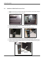
4.5
Installation of the Suction Brake Unit
1. Remove the Suction Brake, three mounting screws and two connector cover mounting screws
from accessories Box 2.
2. Mount the Suction Brake Unit onto the four mounting holes as shown in Figure 4-1.
Figure 4-1
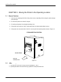
3. Fasten the Suction Brake (Figure 4-2) using the three mounting screws supplied.
4. Connect the 3P connector of the Form End Sensor to the Suction Brake Unit.
5. Mount the 3P connector cover with the two remaining screws supplied.
3P Connector
Figure 4-2
12
INSTALLATION GUIDE
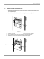
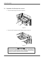
4.6
Installation of Web Guide/Connector Panel
1. Remove the filler plate (2 screws) from lower side cover beneath the suction brake. See figure
below.
2. Remove the lower right side cover from the printer.
Filler Plate
Lower Side Cover
3.
4.
5.
6.
Mounting Screws
Connector Panel
Remove the four mounting screws securing the connector panel to the mounting bracket.
Feed the connector panel through the hole of the lower sides cover.
Mount the lower side cover.
Remove the contents of accessory Box 3 containing the Web Guide assembly.
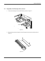
7. Remove the filler plate from the Web Guide Box and discard, retain (4) 6mm screws.
8. Feed the Connector Panel Assembly through the Web Guide Box as shown in the figure above.
9. Attach the Connector Panel Assembly through the Web Guide Box and attach with the (4) M4 x
6mm long screws provided.
Web Guide Box
Assembled
13
INSTALLATION GUIDE
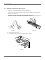
Installation of Web Guide/Connector Panel, continued
10. Position the Box Assembly under the suction brake of the printer locating the edge 5 ¾” from the
edge of the front printer cover. See Figure below.
11. Place the roller shaft (Item 2) in the grooves of the Web Guide Assembly (Item 1) and adjust the
spring plungers so that the roller shaft does not pull out of the grooves during printer operation.
Roller Shaft
Web Guide
Assembly
14
INSTALLATION GUIDE
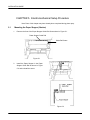
CHAPTER 5. Electromechanical Setup Procedure
Note: Parts of this chapter may have already been completed during printer prep.
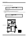
5.1
Mounting the Paper Stopper (Stacker)
1.
Remove the front of the Paper Stopper Guide Rail Screw shown in Figure 5-1.
Paper Stopper Guide Rail
Guide Rail Screw
Figure 5-1
2.
Install the Paper Stopper in the Paper
Stopper Guide Rail as shown in Figure
5-2 and re-install the screw.
Figure 5-2
15
INSTALLATION GUIDE
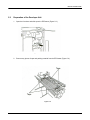
5.2
Preparation of the Developer Unit
1.
Open the front door and slide open the EP Drawer (Figure 5-3.)
Figure 5-3
2.
Remove any pieces of tape and packing material from the EP Drawer (Figure 5-4).
Figure 5-4
16
INSTALLATION GUIDE
5.2
Preparation of the Developer Unit, continued
3.
Remove the Main Charge Unit as shown in Figure 5-5.
30
Figure 5-5
4.
Remove the OPC Cartridge form the EP Drawer as shown in Figure 5-6
Figure 5-6
!
WARNING
!
Do not touch the organic photoconductor (OPC) drum. If the OPC Drum is
exposed as-is, and the cartridge is kept in a bright light, it will not function
properly. Limit indoor exposure to less than 10 minutes.
17
INSTALLATION GUIDE
5.2
Preparation of the Developer Unit, continued
5.
Remove the Developer Unit from the EP Drawer as shown in Figure 5-7.
Figure 5-7
6.
Remove the two screws securing the lid of the Developer Unit and remove the lid as shown in
Figure 5-8.
Figure 5-8
18
INSTALLATION GUIDE
5.2
Preparation of the Developer Unit, continued
7.
Remove one of the developer powder boxes from accessories Box 2.
8.
One at a time cut the corner of each packet and add the developer powder to the developer unit as
shown in Figure 5-9 and 5-10.
9.
Evenly pour the contents of two packages of developer powder into the developer unit while rotating
the developer drive gear in the direction of the arrow as shown in Figure 5-10.
Figure 5-9
Figure 5-10
10. Re-install the developer unit lid.
11. Re-install the developer unit into the EP Drawer as shown in Figure 5-11.
Figure 5-11
19
INSTALLATION GUIDE
5.2 Preparation of the Developer Unit, continued
12. Install the OPC Cartridge in the EP Drawer as shown in Figure 5-12.
Figure 5-12
13. Install the Main Charger Unit on the OPC Cartridge as show in Figure 5-13.
14. Slide the EP drawer closed, Figure 5-14.
Figure 5-14
Figure 5-13
20
INSTALLATION GUIDE
5.3
Controller Installation, Meto-Logic
!
CAUTION
!
The printer power cord must not be connected until after the controller
has been installed.
1.
2.
3.
4.
Open lower Front Door.
Locate power strip above main power supply cabinet (see Figure 5-17).
Position the Controller in the lower cabinet as shown in Figure 5-15.
Connect the monitor AC power cord from the connector panel harness to the Unswitched AC receptacle of
the Printer.
!
WARNING
!
Before installation, the Controller power supply voltage selector switch
must be set to the 230V position.
AC Power Strip
Controller
Figure 5-15
21
INSTALLATION GUIDE
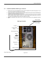
5.3
Controller Installation, Meto-Logic, continued
5. Attach the AC power cord supplied from the AC output receptacle of the power strip (Figure 5-17) to
the input AC receptacle of the Meto-Logic controller.
6. Attach the AC power cord supplied from the AC input receptacle of the power strip to the Switched AC
receptacle of the Printer as shown in Figure 5-17.
7. Attach one end of the ground strap to the rear of the controller frame and the other end to an available
printer chassis screw as shown in Figure 5-16. Leave enough ground strap slack to allow the
controller to be completely removed from lower cabinet for service.
8. Attach the appropriate data cables from the connector panel harness to the appropriate controller
ports.
Printer Chassis
Meto Logic-Controller
Ground Strap
AC Input
115/230V Power
Setting
RS-232 (Com1 Port)
Parallel
Port
Monitor Port
USB Port (4)
Ethernet Port
TDU Port
PIFCII Connector
Printer Power Cable
Figure 5-16
22
INSTALLATION GUIDE
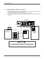
5.3
Controller Installation, Meto-Logic, continued
Attach the Blue TDU cable from the connector panel harness to the controller's TDU port as shown in
Figure 5-16. Make sure the connector is securely seated.
10. Confirm that the controller voltage selector switch is set to the 230V position.
11. Place the Controller back into the lower printer compartment with the front of the controller facing the
front door.
9.
Power Switch
Power Strip
AC Outputs
AC Input
On
Off
Power
Strip
Main
Power Supply
Connector Panel
TOTAL 200-240V,
50-60Hz,3.5A
Meto-Logic
Controller
Switched
Un-Switched
Figure 5-17
!
WARNING
!
Before connecting the Controller power cord, confirm that the Controller
power supply voltage selector switch is set to the 230V position.
23
INSTALLATION GUIDE
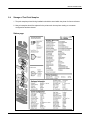
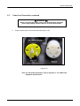
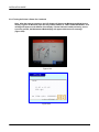
5.4
Storage of Test Print Samples
1. Test print samples printed during installation should be stored within the printer for future reference.
2. New print samples should be replaced in the printer each time a printer setting or a customer
configuration has been altered.
Status page:
24
INSTALLATION GUIDE
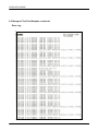
5.4 Storage of Test Print Samples, continued
Error Log:
25
INSTALLATION GUIDE
5.4 Storage of Test Print Samples, continued
Character Fill:
26
INSTALLATION GUIDE
5.5
Power Cord Connection
Note:
If the printer is being installed in a country location other that the U.S. or Canada, it may
be necessary to change the power cord. Consult Appendix B for further information.
1. Check that the printer circuit breaker is in the OFF position (Figure 5-18).
Figure 5-18
2. Check that the printer power switch, on the side of the printer is in the OFF (0)
position (Figure 5-19).
Figure 5-19
27
INSTALLATION GUIDE
5.5
Power Cord Connection, continued
!
WARNING
!
Before connecting the Printer power cord, confirm that the Controller
power supply voltage selector switch is set to the 230V position.
3.
Plug the printer power cord into the wall outlet (Figure 5-20).
LP 100R AC Power
Figure 5-20
Note: For wall outlet specification, refer to Appendix C, "LP 100R Printer
Equipment Specifications."
28
INSTALLATION GUIDE
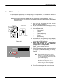
5.6
Main Power-On
!
WARNING
!
Before connecting the Printer power cord, confirm that the Controller
power supply voltage selector switch is set to the 230V position.
1.
Place the printer circuit breaker in the ON position, (Figure 5-21).
Figure 5-21
5.7 Controller Power-On
29
1.
Turn the Printer's main Power switch On (see Figure 5-19).
2.
Confirm that the Remote/Maintenance switch is set to Remote.
3.
Toggle the Power On/Off switch on the Power Strip to the On position (see Figure 5-17).
4.
To turn the Printer On, press the POWER LED switch (see Figure 5-23).
INSTALLATION GUIDE
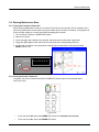
5.8 Entering Maintenance Mode
5.8.1 Turning the Controller's Power Off
Before entering Maintenance mode you must first turn off power to the controller. This is necessary when
performing maintenance functions that may require sudden power off and on conditions. Turning power off
to the controller allows you to work freely without damaging the controller:
1. Turn the Printer Off from the POWER LED switch.
2. Open the front door.
3. Locate the power strip located in the controller cabinet above the main power supply shelf.
4. Toggle the (RED) lighted on/off switch until the switch has been extinguished (power off).
5. Confirm that the position of the panel switch located near the mechanical counter points toward
MAINT (Figure 5-22).
REMOTE
0 1 2 3 4 5 6
MAINT
Figure 5-22
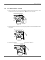
5.8.2 Turning the Printer's Power On
The printer can now be turned on/off with the POWER LED switch located on the operator panel
(see Figure 5-23).
Figure 5-23.
•
To turn the printer Off, press the POWER LED switch for a minimum of 10 seconds.
•
To turn the printer On, press the POWER LED switch.
30
INSTALLATION GUIDE
5.8.2 Turning the Printer's Power On, Continued
Note: After the warm-up sequence, the LCD display will boot to the Maintenance Mode Service
display, Figure 5-24. Because paper has not yet been loaded, an “FMU: FORM UNLOADED” error
message will appear on the bottom of the display. If forms had been loaded previously, and no
errors are present, the Maintenance Mode display will appear without an error message
(Figure 5-25).
Figure 5-24
IDLE
11.0" x 15.0"
600 dpi
LP 100R S/N: 10000000
ISD-202VER1.5.19
Figure 5-25
31
01
INSTALLATION GUIDE
5.9
ATDC Adjustment
• When replacing the developer unit or replacing the developer starter, it is necessary to adjust the
calibration of the ATDC sensor before using the printer.
Note: The developer unit comes supplied with four (4) packages of developer starter. Two (2)
packages are used for the initial charge, and the remaining two (2) packages are to be replaced
at the 400K interval.
TRIMMER VOLUME
GREEN LED
YELLOW LED
Figure 5-26
REMOTE
0 1 2 3 4 5 6
MAINT
1. Open front door and bypass front door Interlock
switch with Interlock switch Jig.
2. Set the Remote/Maintenance switch (Figure 5-27)
to Maintenance.
3. Press the Power switch.
¾ Press [ Off-Line]
¾
[ Maintenance]
¾
[ Service]
¾
[ Adjustment]
¾
[ Starter Adjustment]
¾
[ Enter]
¾
[Are you sure?]
¾
[Yes]
4. The print engine will begin turning and the display
will indicate “Adjust within 3 minutes.” The printer
is now ready for ATDC calibration.
5. Adjust the developer unit potentiometer
(Figure 5-26) until both the Green and Yellow
LED indicators are completely OFF.
6. The ATDC adjustment mode will continue to run for
approx. (3) three minutes and turn off.
7. If the ATDC adjustment has not been accomplished
by the time the mode has completed (3 minutes),
the ATDC adjustment mode will have to be
restarted.
Note: If you rotate the potentiometer counter
clockwise, the green LED will turn off. If
you rotate the potentiometer clockwise, the
yellow LED will light up.
Note: If you rotate the potentiometer clockwise
the yellow LED will turn off. If you
continue to rotate the potentiometer
clockwise the green LED will light up.
Figure 5-27
8.
Turn off the printer power and remove the front
door interlock switch jig.
32
INSTALLATION GUIDE
5.10
Toner Bottle Installation
1. Tap a new Toner Bottle against a desk or other hard surface four or five times as shown in
Figure 5-28. Then turn the Toner Bottle upside down and tap it in the same way again.
Figure 5-28
2.
Shake the Toner Bottle vigorously while rotating the bottle at least five times, Figure 5-29.
Figure 5-29
3.
Swing out the Toner Bottle Holder, Figure 5-30.
Figure 5-30
33
INSTALLATION GUIDE
5.10
Toner Bottle Installation, continued
4.
With the “UP” marking on top, insert the Toner Bottle into position as shown in Figure 5-31. Check
that the black line on the Bottle is aligned with the
marking on the Toner Bottle.
UP
UP
Figure 5-31
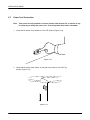
5.
While supporting the Toner Bottle with your hand, gently pull the toner seal off of the Bottle as shown
in Figure 5-32.
Figure 5-32
6.
Swing the Toner Bottle Holder closed and close the Front Door, Figure 5-33.
Figure 5-33
34
INSTALLATION GUIDE
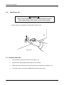
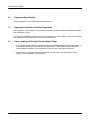
5.11
Power Off
1.
35
Place the Printer Power Switch (Refer to Figure 5-19) into the off position.
INSTALLATION GUIDE
5.12
Final Mechanical Check
1.
After completing the installation, check the following mechanical functions.
■
■
■
■
■
■
■
■
5.13
Check the opening and closing of the Front Cover, Toner Bottle access cover and the
left Side Cover.
Check the Stacker Assembly for smooth operation.
Check the Tractor Assembly for smooth up and down movement.
Check the EP Drawer for smooth operation a well as perfect locking and releasing.
Check Suction Brake unit for proper operation.
Check Web Guide roller for proper forms tension.
Check Swing Guide for proper operation (Optional).
Check Burster Unit for proper operation.
Leveling the Printer
One (1) level and a 20 mm open-end wrench are required for this procedure.
1.
Once a proper location has been found for the printer, the printer should then be secured and leveled
to the floor. The leveling feet at the base of the printer should be adjusted so that the lower surface of
the printer frame is 70 mm above the floor surface as shown in Figure 5-34.
70mm MIN.
LEVELING
FOOT
Figure 5-34
36
INSTALLATION GUIDE
6.1
Equipment Specification
Consult Appendix C for LP 100R Equipment Specifications.
7.1
Equipment Installation Checklist Preparation
After completion of the installation, the Equipment Installation Checklist must be completed by the installer
and submitted for review.
The Equipment Installation Checklist can be found in Appendix H. After completion, remove the checklist
from this manual and immediately return to the specified address.
8.1
37
Paper Loading and Printing Test and Status Pages
1.
If the installer is familiar with the procedures required to load paper and print test and status pages, he
or she should perform them now and then proceed to the LP 100R Operator's Guide, document
number 9855063, Chapter 3: Printer Operation for specific user configuration instructions.
2.
If the installer is not familiar with these procedures, proceed to the LP 100R Operator's Guide,
Chapter 3: Printer Operation for instructions.
INSTALLATION GUIDE
This page is intentionally blank.
38
APPENDIX A
LP 100R PRINTER OPERATING LOCATION REQUIREMENTS
1.1
Operating Location Requirements
Before proceeding with the printer installation, check the following location requirements.
1.1.1
General Site Requirements
To ensure the utmost safety and prevent possible malfunctions of the printer, install it in a location that
meets the following requirements:
1.1.2
1.
Since toner spills can occur, do not locate the printer on vinyl chloride flooring or any other material
not resistant to toner.
2.
Locate away from objects that may catch fire easily.
3.
Locate where there is no possibility of splashing liquids.
4.
Locate in an area free from direct sunlight.
5.
Locate out of direct air stream of an air conditioner, heater, or ventilator.
6.
Locate in a dry place.
7.
Locate in a dust-free place.
8.
Locate on a stable surface.
9.
Locate in a well-ventilated space.
Ventilation Requirements
Locate the printer in a well-ventilated room. A negligible amount of ozone is generated during normal
operation of this printer. An unpleasant odor may, however, be created in poorly ventilated rooms during
extensive printer operations. For a comfortable, healthy, and safe operating environment, it is
recommended that the room be well ventilated.
Be sure to allow a clearance of 6 inches or more in the rear of the printer (at all times) for proper ventilation.
A-1
APPENDIX A
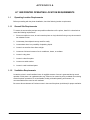
1.1.3
Clearance Requirements
1.1.3.1
Printer Size
Figure A-1 illustrates a front and top view of the printer that provides its overall dimensions as well as the
height and total clearance required when the front and left side covers are fully opened.
Figure A-1 also provides proper media loading distance 13" from the media to the Suction Brake Unit.
720mm (28 3/8")
1000mm (39 3/8")
940mm(37 1/16")
600mm(23 5/8")
1000mm (39 3/8")
1000mm(39 3/8")
PRINTER
720mm (28 3/8") 136mm (5 11/32")
1185mm (46 5/8")
66mm (2 5/8")
Figure A-1
330mm (13")
A-2
APPENDIX A
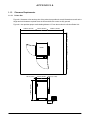
1.1.3.2
Printer Clearance Requirements (Maintenance Area)
Figure A-2 illustrates a printer top view showing the minimum clearance required to maintain and
repair the LP 100R printer. Taking into consideration the width and depth dimensions of the
printer, a space approximately 9’ (2.74 M) X 9’ (2.74 M) is required.
Maintenance Area
9 feet
( 2.74 Meters)
PRINTER
PRINTER
EP
DRAWER
9 feet
( 2.74 Meters)
Figure A-2
A-3
APPENDIX A
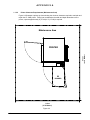
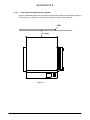
1.1.3.3
Printer Clearance Requirements (Installed)
Figure A-3 illustrates a printer top view showing the minimum clearance required when a printer is
moved to a wall. A minimum of 6” (inches) is required for proper printer ventilation.
Wall
6” inches
Figure A-3
A-4
APPENDIX A
1.1.4
Operating Environment Requirements
1.1.4.1
Temperature
50° F to 95° F (10° C to 35° C) with a temperature variation not exceeding 18° F (10° C).
1.1.4.2
Humidity
35% to 80% RH with a maximum fluctuation of 20% per hour.
1.1.5
Power Source and Grounding Requirements
1.1.5.1
Power Source
The power source requirements are as follows:
1. 200 to 240 VAC (50 or 60 Hz)
2.
Use power source with low frequency fluctuations:
Frequency Fluctuation:
1.1.5.2
Within ± 3%
3.
An isolated, dedicated ground outlet (to prevent interference from other equipment, which can cause
memory loss during printer operation).
4.
Never connect any other appliances or machines to dedicated outlet.
5.
The outlet must be located within 6’ (2M) of the printer and easily accessible.
Grounding Requirements
To prevent receiving electrical shocks in the case of electrical leakage, always ground the printer.
Connect the grounding wire to one of the following grounds:
1.
The ground terminal of the outlet.
2.
A grounding contact that complies with the local electrical standards.
CAUTION
Never connect the grounding wire to a gas pipe, grounding wire for a
telephone, or a water pipe.
A-5
INSTALLATION GUIDE
This page is intentionally blank.
A-6
APPENDIX
B
EUROPEAN POWER CONSIDERATIONS
1.1
POWER CORD INSTRUCTIONS (EUROPE)
DANGER
THIS APPARATUS IS SHIPPED WITH THE POWER SUPPLY
CORD AND THE PLUG WHICH IS CERTIFIED FOR USA AND
CANADA. IF IT IS USED IN EUROPEAN COUNTRIES, THE
POWER SUPPLY CORD AND PLUG SHOULD BE CHANGED
BY THE LAW AS FOLLOWING.
1.1.1
REPLACING THE POWER SUPPLY CORD
1. Remove the factory installed power supply cord.
2. To configure a new power supply cord, the following hardware and tools should be used.
The power supply cords for European Countries should meet the following standards:
(1) Should use three conductor wire whose nominal cross-sectional area is 2.5 mm or more
each.
+20
(2) Should be at 3000 mm -10 long.
(3) Should have '<HAR>' marking.
The terminals should be ring type, appropriate for 6 mm screw and wire as described above,
having approval from VDE, TUV or other agencies.
Crimping tools for the terminals should be used in accordance with instructions by the
manufacturer of the terminals.
Rating Voltage
Power Supply Cord
min 240V
Length
3000
+20
-10
mm
Cross-section Area
2
min 2.5 mm x3
Marking
<HAR>
3. Process the Power Supply Cord as follows.
Strip the Power Supply Cord in length of 40 mm
Cut the BLUE and BROWN wires 10mm shorter than the wire colored GREEN/YELLOW.
Strip the wires the appropriate length for the terminals to be used. Clamp the terminals on the
wire using a tool in accordance with the instruction by the manufacturer of the terminal.
10
BR
BL
G/Y
4. Install a new power supply cord to the Printer in accordance with following procedures.
The wire that is colored GREEN/YELLOW must be connected to the terminal in the printer that
is marked with the letter FG.
The wire that is colored BLUE must be connected to the terminal in the printer that is marked with
the letter N.
The wire that is colored Brown must be connected to the terminal in the printer that is marked with
the letter L.
B-1
APPENDIX
B
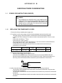
1.1.2 CONFIGURE THE PLUG
1. If the power supply cord is not provided with an attachment plug cap, configure a new plug to the
power supply cord in accordance with following procedures.
2. Prepare a plug that has appropriate rating and agency approval as shown in the table below and
proceed as follows:
Plug Type
250V AC
25A
UK
240V AC
30A or more
(INDUSTRIAL)
Reference
Standards
CEE 7-7
BS 4343
IEC 309-2
EN 60309-2
CEE 17
3. Configure the Power Supply Cord as follows:
Strip the Power Supply Cord.
Strip the wires as appropriate for the terminal of plug used.
4. Install a new plug to a power supply cord using the correct color configuration.
The wire that is colored GREEN/YELLOW must be connected to the terminal in the plug which could be
marked by the letter E or PE or by the earth symbol or colored GREEN or GREEN/YELLOW.
The wire that is colored BLUE must be connected to the terminal in the printer that is marked with the
letter N or colored BLACK.
The wire that is colored BROWN must be connected to the terminal in the printer that is marked with
the letter L or W or colored RED.
1.1.3
CONFIRM THE GROUND
Please reconfirm that the grounding conductor in the supply cord is connected between the terminal
in the printer that is marked with the letter FG and the terminal in the plug which could be marked with
the letter E or PE or by the earth symbol or colored GREEN or GREEN/YELLOW.
WARNING
THIS APPARATUS MUST BE PROPERLY GROUNDED.
B-2
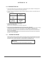
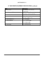
APPENDIX C
LP 100R PRINTER EQUIPMENT SPECIFICATIONS
Item
Description
1. Printing Method
■
Dry Electro Photographic
■
Laser Diode Exposure
2. Printing Speed
■
3,300 LPM (6LPI)
3. Printing Resolution
■
240/300/400/480/600 DPI (Changeable)
■
400 is standard
4. Print Duty (B/W Ratio)
■
Max. 25% (TBD)
5. Fusion Method
■
Flash (Xenon Lamp)
a) Maximum Width
■
Max. 17" (431.8 mm)
b) Maximum Length
■
Max. 233/4" (603.25 mm)
a) Width
■
6 to 18 inches (152.4 to 457.2 mm)
b) Length
■
5 to 24 inches (127 to 609.6 mm)
c) Thickness
■
3 to 11 MIL
■
11.8 inches (300 mm)
a) Minimum Length
■
7.5 inches
b) Maximum Length
■
12 inches
c) Maximum Thickness
■
4 MIL
a) Maximum Height
■
11.7 inches (297.2 mm)
b) Maximum Width
■
18 inches (457.2 mm)
c)
■
16 inches (406.4 mm)
6. Printing Area
7. Paper
8. Paper Supply (Height)
9. Paper (Swing Guide Option)
10. Paper Stacker Capacity
Maximum Length
11. Maximum Ejection Size
■
18" (457.2 mm) width x 16" (406.4)
■
Standard stacker table is 12" (304.8 mm)
Table C-1
LP 100R Printer Specification, continued
C-1
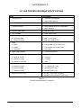
APPENDIX C
LP 100R PRINTER EQUIPMENT SPECIFICATIONS, continued
Item
Description
12. Power Source
■
Universal (AC 200 to 240 VAC)
(50 or 60 Hz)
13. Heat Dissipation (BTU)
■
Operating: 8560 BTU/hr (2508 Wh)
■
Stand-by: 578 BTU/ hr (169.5 Wh)
14. Actual Current Draw
■
16 Amp
15. Acoustic Noise
■
Stand-by: 50dB (A) or less
■
Printing: 62dB (A) or less
16. Wall Receptacle (U.S.)
■
LP-30R (NEMA)
17. Printer Dimensions
■
47" (1,194 mm) height
■
36" (914 mm) width
■
37" (940 mm) depth
■
572 pounds (260 kg)
18. Printer Weight
C-2
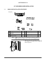
APPENDIX D
LP 100R SWING GUIDE INSTALLATION
1.1
SWING GUIDE INSTALLATION PROCEDURE
Packing list
1
5
2
6
3
7
4
8
1
2
3
4
Swing guide assembly
Swing
guide
drive
motor
assembly
Paper guide plate assembly
Screw (3×5 mm)
1
1
5
6
Paper guide
Screw (4x8 mm)
2
11
2
14
7
8
Cover (sensor)
Magnet assembly
1
1
Note: : • Lower the stacker table to the lowest position to facilitate the installation
work.
• Before starting the installation work, turn OFF the main POWER switch.
1. Open the front door, and remove the lower left
cover (black) by removing the four screws as
shown in Figure D-1.
Figure D-1
D-1
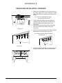
APPENDIX D
SWING GUIDE INSTALLATION, CONTINUED
2. Remove the blind plate from the printer frame for
the swing guide drive motor assembly located
above the PWB-F/SC board by removing the two
screws.
Note: The removed blind plate is no longer
necessary. Store it, if necessary.
Figure D-2
3. Position the swing guide drive motor assembly
while shifting it to the right of the printer body by
temporarily fastening the three screws. (See
Figure D-2)
4. Connect the connector (6P) from the swing guide
drive motor assembly to PWB-F (PJ6). (See
Figure D-2)
5. Install the two paper guides to the Printer body by
fastening the five screws.(See Figure D-3)
The two paper guides (L and R) are identical
with each other .
Figure D-3
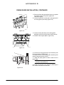
6. Mount the Magnet assembly to the printer body as
shown in Figure D-4 and fasten with two screws.
Figure D-4
D-2
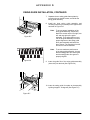
APPENDIX D
SWING GUIDE INSTALLATION, CONTINUED
7. Separate the two swing guide frame plates by
removing the two thumb screws, and divide the
swing guide assembly.
8. Install the inner swing guide assembly and
mounting brackets (four screws) to the upper frame
as shown in Figure D-5.
Note:
To ensure proper installation of the
swing guide assembly, temporarily
fasten the screws at the front right, rear
left, and rear right of the guide
assembly. Then adjust the front and
rear of the guide assembly to ensure
proper alignment to the swing guide
drive gear assembly and fasten the
three screws. The remaining front left
screws can now be fastened.
Note:
To ensure maximum performance
of the swing guide assembly, be sure
that the swing guide drive motor gear
and the swing guide drive gear are
properly aligned.
Figure D-5
Figure D-6
9. Insert the guide film of the swing guide assembly
(inner side) into the hole.(See Figure D-6)
10. Insert the swing guide front plate to the assembly
by tilting it approx. 30 degrees (See Figure D-7)
Figure D-7
D-3
APPENDIX D
SWING GUIDE INSTALLATION, CONTINUED
11. Swing the front plate upward and secure up against
the bottom frame of the printer against the
stationary magnet.
12. Insert the guide film into the hole in the upper part of
the swing guide (front side).(Figure D-8)
GUIDE FILM
Figure D-8
SCREW
SCREW
13. Lower the front plate down to the swing guide
assembly and secure with the two knurled screws.
14. Install the two support plates. (Figure D-9)
SUPPORT PLATES
Figure D-9
15. Connect the swing guide drive gear assembly with
the one connector. (Figure D-10)
16. Install the cover to the swing guide assembly (front
side) by fastening the two screws.
17. Install the paper guide at 30mm inside from the
paper edge.
Note: When installing the burster unit, redo the
connection of the burster unit.
18. Install the lower-left cover (black) by fastening the
four screws, and close the front door.
Figure D-10
D-4
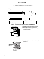
APPENDIX E
LP 100R BURSTER UNIT INSTALLATION
Packing list:
1
3
4
5
2
1
Burster unit
1
4
2
3
Paper guide
Harness assembly
1
1
5
Caution:
Fixing screws (4×8 mm)
Label
2
1
Before starting the installation, turn OFF the main POWER switch.
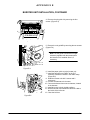
1. Open the front door, and open the toner bottle.
2. Remove the cover before the fusing unit by
removing six screws, the upper-left cover by
removing one screw, and the lower-left cover by
removing four screws.
Figure E-1
3. Open the left-side door and remove the fuser filter.
(Figure E-2)
Figure E-2
E-1
APPENDIX E
BURSTER UNIT INSTALLATION, CONTINUED
4. Remove the exit guide A by removing the four
screws. (Figure E-3)
A
Figure E-3
5. Remove the exit guide B by removing the two screws.
(Figure E-4)
B
Note: The exit guide A and B are no longer
necessary together with the screws when
the burster unit is installed. Store it, if
necessary.
Figure E-4
6. Install the paper guide on to the burster unit.
7. Install the harness on to PWB-F to the PJ-7
connector. Install the harness in the cable clamp.
(Figure E-5)
8. Install the burster unit with 2 screws and 2
connectors.
9. Connect the harness to the burster.
10. Connect the burster home sensor harness, located
in the harness.
11. Install all covers in their original positions.
12. Stick the Burster Jam Removal Instruction Label to
the inside of the left cover.
13. Close the left door.
Figure E-5
E-2
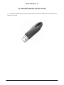
APPENDIX F
LP 100R IPDS USB KEY INSTALLATION
1. To enable the IPDS Emulation, the Sentinel Key shown below must be installed into the USB port of the
Meto-Logic controller.
F-1
INSTALLATION GUIDE
This page is intentionally blank.
F-2
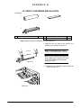
APPENDIX G
LP 100R PC CARTRIDGE INSTALLATION
Packing list
3
1
2
1
PC drum
1
2
3
PC cleaning unit
Cleaner blade
1
1
Note1: Before starting the installation, turn the printer OFF.
1. Install the new PC drum to the stops in the
cleaning unit as shown in Figure G-1.
PC DRUM
Figure G-1
Note: To avoid damage to PC drum
surface, avoid direct contact to surface.
Note: Use the supplied cleaning pad or
other suitable item to shield the PC drum
from contact damage and prolonged
exposure to light.
2. Re-install the PC cartridge in the EP drawer as
shown in Figure G-2.
Figure G-2
G-1
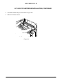
APPENDIX G
LP 100 R PC CARTRIDGE INSTALLATION, CONTINUED
3. Re-install the Main Charger Unit as shown in Figure G-3.
4. Slide the EP Drawer closed.
Figure G-3
G-2
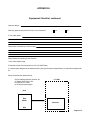
APPENDIX H
LP 100R PRINTER EQUIPMENT INSTALLATION CHECKLIST
In order to permit the SATO Printer Product Support Group to maintain an adequate Customer Database for those
Customers using the LP 100R Printer, it is imperative that the attached Equipment Checklist be completed,
removed from Appendix H, and returned to the SATO Product Support Group after installation has been
completed.
Please keep in mind that without adequate documentation, the SATO Help Desk may be unable to quickly respond
to your request for technical assistance, should the need to do so arise.
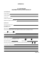
APPENDIX H
LP 100R PRINTER
EQUIPMENT INSTALLATION CHECKLIST
CUSTOMER DATA
Company Name:
Company Address:
Contact Name:
Location of closest Airport:
Distance from Airport to Customer site:
SALES DATA
Sales Representative Name:
EQUIPMENT DATA
Date Received:
Did the printer shipping container or any additional containers sustain any damage in-transit?
Yes
No
If Yes, please describe the damage:
Date Equipment Installed:
Did the Customer provide Dedicated A.C. Lines?
Printer Serial Number:
Yes
No
Page Counter =
Was either the Printer or the Controller or any optional equipment damaged in any way?
Yes
No
If Yes, please describe damage:
Page 1 of 3
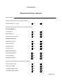
APPENDIX H
Equipment Checklist, continued
Customer Name:
Were the following items received with the Printer?
Yes
No
Toner Bottle (1)
Yes
No
Paper Stopper (1)
Yes
No
Developer Starter (2) boxes
Yes
No
Suction Brake Unit (1)
Yes
No
Cleaning Cloth (1)
Yes
No
Cleaning Brush (1)
Yes
No
Cleaning Pen (1)
Yes
No
Universal Web Guide (1)
Yes
No
Conveyor Roller(1)
Yes
No
Installation Procedure
Yes
No
Accessory Box No.1, 2, and 3
Were the following items received in the accessory boxes?
Accessory Box No.1
Accessory Box No.2
Accessory Box No.3
Were the following items received with the Controller?
Controller Power Cord
Yes
No
Power Cord Adapter
Yes
No
LP 100R Installation Guide
Yes
No
LP 100R Operations Manual
Yes
No
Page 2 of 3
APPENDIX H
Equipment Checklist, continued
Customer Name:
Were any parts missing from the Printer or the Controller?
Yes
No
If Yes, which parts?
Please enter comments you wish to make:
Please attach the following to this checklist:
1.The Printer Status Page
2.Samples of each document printed on the LP 100R Printer
3. A system block diagram for the installed printer (See typical system example below). A simple block diagram will
do.
Return Checklist with attachments to:
SATO Labeling Solutions America, Inc.
30 Chapin Road, Suite 1201
Pine Brook, NJ 07058
Att: Printer Product Support
LP 100R
Host
IBM
AS400
Controller
IBM
Page 3 of 3
II-3IIyyiiyIII
This page is intentionally blank.
APPENDIX H
This page is intentionally blank.
Published by:
SATO America, Inc.
LP 100R
Installation Guide
Publication
ID # 9855148
March 2009
RELATED PUBLICATIONS
LP 100R Maintenance Guide
LP 100R Operator’s Guide
LP 100R Unboxing Instructions
9855143
9855063