1
Australia
Japan
Datalogic Scanning Pty Ltd
North Ryde, Australia
Telephone: [61] (2) 9870 3200
Fax: [61] (2) 9878 8688
Datalogic Scanning KK
Shinagawa, Tokyo, Japan
Telephone: 81 (0)3 3491 6761
Fax: 81 (0)3 3491 6656
France and Benelux
Latin America
Datalogic Scanning Sarl
LES ULIS Cedex, France
Telephone: [33].01.64.86.71.00
Fax: [33].01.64 46.72.44
Datalogic Scanning, Inc
Miami, Florida, USA
Telephone: (305) 591-3222
Fax: (305) 591-3007
Germany
Spain and Portugal
Datalogic Scanning GmbH
Darmstadt, Germany
Telephone: 49 (0) 61 51/93 58-0
Fax: 49 (0) 61 51/93 58 58
Datalogic Scanning Sarl
Sucursal en España
Madrid, Spain
Telephone: 34 91 746 28 60
Fax: 34 91 742 35 33
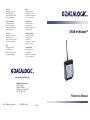
STAR
Modem™
Italy
Datalogic Scanning SpA
Vimercate (MI), Italy
Telephone: [39] (0) 39/62903.1
Fax: [39] (0) 39/6859496
United Kingdom
Datalogic Scanning LTD
Watford, England
Telephone: 44 (0) 1923 809500
Fax: 44 (0) 1923 809 505
www.scanning.datalogic.com
Datalogic Scanning, Inc.
959 Terry Street
Eugene, OR 97402
Telephone: (541) 683-5700
Fax: (541) 345-7140
Reference Manual
©2007 Datalogic Scanning, Inc.
820002020 (Rev. A)
10/07
Datalogic Scanning, Inc.
959 Terry Street
Eugene, Oregon 97402
Telephone: (541) 683-5700
Fax: (541) 345-7140
An Unpublished Work - All rights reserved. No part of the contents of this documentation or the
procedures described therein may be reproduced or transmitted in any form or by any means
without prior written per-mission of Datalogic Scanning, Inc. or its subsidiaries or affiliates
("Datalogic" or “Datalogic Scanning”). Owners of Datalogic products are hereby granted a nonexclusive, revocable license to reproduce and transmit this documentation for the purchaser's
own internal business purposes. Purchaser shall not remove or alter any proprietary notices,
including copyright notices, contained in this documentation and shall ensure that all notices
appear on any reproductions of the documentation.
Should future revisions of this manual be published, you can acquire printed versions by
contacting your Datalogic representative. Electronic versions may either be downloadable from
the Datalogic website (www.scanning.datalogic.com) or provided on appropriate media. If you
visit our website and would like to make comments or suggestions about this or other Datalogic
publications, please let us know via the "Contact Datalogic" page.
Disclaimer
Datalogic has taken reasonable measures to provide information in this manual that is complete
and accurate, however, Datalogic reserves the right to change any specification at any time
without prior notice. Datalogic is a registered trademark of Datalogic S.p.A. in many countries
and the Datalogic logo is a trademark of Datalogic S.p.A. all licensed to Datalogic Scanning,
Inc. All other trademarks and trade names referred to herein are property of their respective
owners.
19/10/2007
CONTENTS
HOW TO USE THIS MANUAL .....................................................................vi
1
1.1
INTRODUCTION .......................................................................................... 1
LED Indicators .............................................................................................. 1
2
2.1
2.1.1
2.1.2
2.2
2.2.1
2.2.2
2.3
2.3.1
2.3.2
2.3.3
MOUNTING AND CONNECTIONS .............................................................. 3
Basic System Layouts................................................................................... 3
Stand Alone Mode ........................................................................................ 3
STAR-System™ Mode.................................................................................. 4
STARModem™ Installation........................................................................ 5
Mounting Brackets ........................................................................................ 5
Antenna ........................................................................................................ 7
System Connections ..................................................................................... 8
RS232 Interface Connection ......................................................................... 9
Pen Emulation Interface Connection............................................................. 9
Wedge Interface Connection....................................................................... 10
3
3.1
3.1.1
3.2
3.2.1
INITIAL SETUP .......................................................................................... 11
Defining the Setup ...................................................................................... 12
Configuration Strings .................................................................................. 13
Setup for Stand Alone Mode ....................................................................... 14
STARModem™ Receiver (Server)........................................................... 14
Restore Default ........................................................................................... 14
Set Radio Address ...................................................................................... 14
Interface Selection ...................................................................................... 14
STARModem™ Transmitter (Client) ........................................................ 16
Restore Default ........................................................................................... 16
Set Radio Address ...................................................................................... 16
Setup for Star-System™ Mode ................................................................... 17
Restore Default ........................................................................................... 17
Set Radio Addresses .................................................................................. 17
3.2.2
3.3
4
CONFIGURATION...................................................................................... 18
RS232 PARAMETERS ............................................................................... 20
Baud Rate ................................................................................................... 21
Parity........................................................................................................... 21
Data Bits ..................................................................................................... 21
Stop Bits...................................................................................................... 21
Handshaking ............................................................................................... 22
ACK/NACK Protocol ................................................................................... 22
FIFO............................................................................................................ 22
iii
Inter-Character Delay.................................................................................. 22
RX Timeout ................................................................................................. 22
Frame Packing............................................................................................ 22
WEDGE PARAMETERS ............................................................................ 23
Keyboard Nationality................................................................................... 24
Caps Lock ................................................................................................... 24
Num Lock.................................................................................................... 24
Inter-Character Delay.................................................................................. 24
Keyboard Setting ........................................................................................ 25
Inter-Code Delay......................................................................................... 26
Control Character Emulation....................................................................... 26
PEN EMULATION ...................................................................................... 27
Operating Mode .......................................................................................... 28
Minimum Output Pulse................................................................................ 28
Conversion to Code 39 and Code 128........................................................ 28
Overflow...................................................................................................... 28
Output Level................................................................................................ 29
Idle Level..................................................................................................... 29
Inter-Block Delay......................................................................................... 29
DATA FORMAT.......................................................................................... 30
Code Identifier............................................................................................. 32
Custom Code Identifier ............................................................................... 32
Header ........................................................................................................ 33
Terminator................................................................................................... 33
Header Position .......................................................................................... 34
Code Length TX.......................................................................................... 34
Address Stamping....................................................................................... 34
Address Delimiter........................................................................................ 34
RADIO PARAMETERS .............................................................................. 35
RF Baud Rate (not for USA model)............................................................. 36
Transmission Mode (Client only)................................................................. 36
Radio Protocol Timeout (Client only) .......................................................... 36
Single Store (Client only) ............................................................................ 36
ACK/NACK From Remote Host (Client only) .............................................. 37
Beacon (Client only).................................................................................... 37
5
5.1
5.2
5.2.1
5.2.2
5.2.3
5.2.4
iv
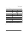
REFERENCES ........................................................................................... 38
Radio and Serial Communication Controls ................................................. 38
RS232 Parameters ..................................................................................... 44
Handshaking ............................................................................................... 44
ACK/NACK Protocol ................................................................................... 46
RX Timeout ................................................................................................. 47
FIFO............................................................................................................ 47
5.2.5
5.3
5.3.1
5.3.2
5.3.3
5.3.4
5.3.5
5.4
5.4.1
5.4.2
5.4.3
5.5
5.5.1
5.5.2
5.5.3
5.5.4
5.5.5
5.5.6
Frame Packing............................................................................................ 48
PEN Emulation Parameters ........................................................................ 50
Minimum Output Pulse................................................................................ 50
Overflow...................................................................................................... 50
Conversion to Code 39 and Code 128........................................................ 50
Output and Idle Levels ................................................................................ 51
Inter-Block Delay......................................................................................... 51
Data Format ................................................................................................ 52
Header/Terminator Selection ...................................................................... 52
Address Stamping....................................................................................... 55
Address Delimiter........................................................................................ 57
Radio Parameters ....................................................................................... 57
RF Baud Rate (not for USA Model)............................................................. 57
Transmission Mode (Client only)................................................................. 57
Radio Protocol Timeout (Client only) .......................................................... 58
Single Store (Client only) ............................................................................ 58
ACK/NACK From Remote Host (Client only) .............................................. 58
Beacon (Client only).................................................................................... 60
6
DEFAULT CONFIGURATION .................................................................... 61
7
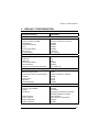
TECHNICAL FEATURES ........................................................................... 63
A
A.1
A.2
A.3
A.4
A.5
TYPICAL SYSTEM LAYOUTS................................................................... 64
Stand Alone Mode - STARModem™ Server............................................ 65
Stand Alone Mode - STARModem™ Server............................................ 66
STAR-System™ Mode - STARModem™ Client ...................................... 67
STAR-System™ Mode - Bi-Directional Communication ................................... 68
STAR-System™ Mode - STARModem™ client ....................................... 69
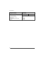
B
HEX AND NUMERIC TABLE ..................................................................... 71
GLOSSARY................................................................................................ 72
v
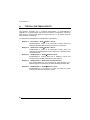
HOW TO USE THIS MANUAL
Your modem is supplied with its own Quick Reference Manual which provides
connection diagrams, basic application parameter settings using configuration
strings, default values, and specific technical features. You can see either your
modem's Quick Reference Manual or this manual for initial configuration.
Initial configuration must be performed through the RS232 interface.
To use this manual for initial setup see chapter 3.
If you need to change the default settings for your specific application, see chapter 4
and the Examples in appendix A.
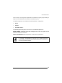
DL Sm@rtSet
DL Sm@rtSet program, available on the installation CD-ROM, is a Windows-based
utility program providing a quick and user-friendly configuration method via RS232.
It allows defining the desired parameter values and sending the complete
configuration directly to the connected STARModem™ via serial interface.
In addition, it also transmits software upgrades to the connected device.
Sending Configuration Strings from Host
This configuration method may be used for initial and complete configuration by
sending the desired strings provided in Chapter 4 through the RS232 interface. Batch
files containing the desired parameter settings can be prepared to configure the
modem quickly and easily.
Reference notes describing the operation of more complex parameters are given in
chapter 5.
Reading Configuration Barcodes
This configuration method allows setting STARModem™ by reading configuration
barcodes with a Datalogic RF device and sending the commands to the modem via
radio.
Initial configuration cannot be performed using this method. However, this method is
particularly useful in changing configuration parameters of a STARModem™
working in Wedge or Pen Emulation interfaces (except radio parameters, which must
be configured in RS232).
All barcodes are provided in the “STARModem™ Configuration Using Barcodes”
document available on the CD-ROM.
vi
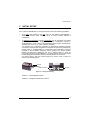
INTRODUCTION
1
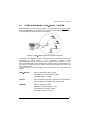
INTRODUCTION
STARModem™ is a radio modem developed to provide wireless 433 MHz RF
(European models) / 910 MHz (USA model) communication between any serial
device (Host) and Datalogic RF devices or base stations, such as:
-
Gryphon™ M Readers
-
Dragon™ M Laser Scanners
-
STARModem™ Radio Modems
-
Formula Basic Line RF Terminals (F734-E/RF, F725-E/RF, F660-E/RF)*
-
STARGATE™ Base Stations
*
not compatible with STARModem™ USA model.
STARModem™ can be configured to communicate either in Stand Alone Mode
(see par. 2.1.1) or STAR-System™ mode (see par. 2.1.2).
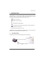
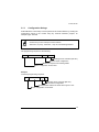
1.1
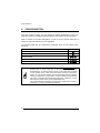
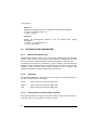
LED INDICATORS
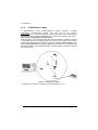
STARModem™ has three LEDs as displayed in the following figure:
Figure 1 - STARModem™ LED Side
1
STARModem™
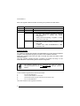
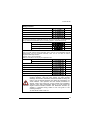
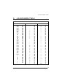
Each LED signals a different modem functioning as reported in the table below:
LED
Power On
TX/RX
Status
Green constant
Yellow blinking
Off
Red constant
DESCRIPTION
STARModem™ is powered.
STARModem™ is receiving or transmitting data.
STARModem™ is working correctly.
-
Red blinking
-
-
at startup, after firmware download, it indicates
that the system is working with default
configuration.
during normal functioning it signals a wrong
connection to the Host.
it blinks during a programming command
execution. In case of wrong command, it will
blink faster;
it blinks once when STARModem™ radio
transaction fails.
Software Upgrade
It is possible to upgrade the software of STARModem™ by using the DL Sm@rtSet
program or the Downloader program provided on the installation CD-ROM.
During this procedure the Power On LED is off while the TX/RX and Status LEDs
blink alternatively.
Once the software upgrade has been completed, the Status LED stays on and
STARModem™ starts working with its default configuration.
NOTE
The software upgrade can be performed only when the Frame
Packing parameter is set to “Frame + [CR]” value (see par. 5.2.5 for
details).
In case of software upgrade failure, follow the given steps:
1)
turn off STARModem™;
2)
connect STARModem™ to the Host;
3)
start the Downloader program until it asks for the device reset;
4)
turn on STARModem™.
The modem software will be upgraded successfully.
2
MOUNTING AND CONNECTIONS
2
MOUNTING AND CONNECTIONS
2.1
BASIC SYSTEM LAYOUTS
There are two basic system layouts that can be employed: stand alone and
STAR-System™ (for other layouts refer to the examples given in appendix A).
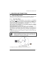
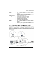
2.1.1
Stand Alone Mode
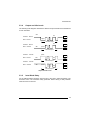
In Stand Alone mode, STARModem™ can be setup in uni-directional
communication to either receive data via radio from Datalogic RF devices, or transmit
data via radio to Datalogic RF devices. Currently supported devices are RF
hand-held readers, another STARModem™ or RF terminals loading STAR&Play™
software (not compatible with STARModem™ USA model).
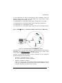
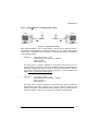
When receiving data, STARModem™ as a Server works like a Datalogic
OM-cradle (refer to STARModem™ 1 in the figure below); therefore, the received
data will only be sent to the connected Host.
Since STARModem™ functions as a cradle in this configuration, all the
multistandard interface selections are valid (RS232, Wedge, Pen Emulation).
STARModem™ in transmission (refer to STARModem™ 2 in the figure below) as
Client works like a data collection RF Device (ex. DRAGON™ M) transmitting the
collected data via radio to the destination Stand Alone device (STARModem™ or
cradle).
In Stand Alone mode, the system implements a different RF Narrow Band radio
protocol than STAR-System™.
NOTE
For communicating with STARModem™ in Stand Alone mode,
configure all Datalogic RF devices by using the commands of the
Stand Alone Mode procedure available in the “RF Device Setup For
STARModem™” document on the CD-ROM.
1
2
Figure 2 - Stand Alone Mode
To configure the modem for operating in this mode refer to par. 3.2.
3
STARModem™
2.1.2
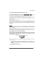
STAR-System™ Mode
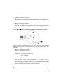
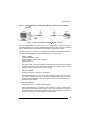
In STAR-System™ mode, STARModem™ uniquely provides a wireless
bi-directional communication between the Host and the RF devices.
STARModem™ 1 in the figure below is a Server (receiver) to the RF Devices and
also a Client (transmitter) to STARModem™ 2, which receives data for the printer.
This mode is only for RS232 communication.
STAR-System™ uses the Narrow Band RF radio and Datalogic CSMA/CA protocol
to automatically link and manage all the RF devices in the system. This protocol
manages the data transmission using a 16-bit CRC checksum. All RF devices in the
system must implement the CSMA/CA protocol and therefore be configured using
the STAR-System™ setup procedure (refer to STARModem™ and the RF devices
in the figure below).
1
2
Figure 3 – STAR-System™ Mode
To configure the modem for operating in this mode refer to par. 3.3.
4
MOUNTING AND CONNECTIONS
2.2
STARModem™ INSTALLATION
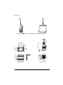
STARModem™ can be installed to operate in different positions by means of two
different mounting brackets and an adjustable antenna.
The four screw holes (M4 x 5) on the body of the modem are for mechanical fixture.
The diagram below gives the overall dimensions of the modem and may be used for
its installation.
6.7
84
3.3
170.7
mm
inch
7.6
0.39
68
32.7
1.3
2.7
Figure 4 - STARModem™ Overall Dimensions
2.2.1
Mounting Brackets
Two different mounting brackets are provided to guarantee the best positioning
according to your application.
The following figures display two possible mounting positions and give the overall
dimensions of each bracket which may be used for their installation.
5
STARModem™
Figure 5 - STARModem™ Standard Positions Using Mounting Brackets
9
0.35
7.8
0.3
4.2
0.16
= 50 =
= 1.96 =
40
73
2.87
4.5 n. 2
0.17 n. 2
2.5
0.09
26
1.02
15
0.59
20°
4.2 6
0.1
32
1.26
R
= 40 =
= 1.57 =
30
1.18
13.8
0.54
17.5
0.68
3
0.11
4.2 n
°2
0.16
n° 2
7.5
0.29
2.5
0.09
25
0.98
46
1.81
90°
= 35 =
= 1.37 =
Figure 6 - ST-217
6
23
0.9
Figure 7 - ST-133
MOUNTING AND CONNECTIONS
2.2.2
Antenna
Before proceeding with this operation ensure that the modem is not
powered.
WARNING
An adjustable antenna on top of the modem can be rotated allowing
STARModem™ installation even in the most critical positions.
In standard position, the antenna is parallel to the modem body as displayed in the
following figure:
Figure 8 - Antenna Standard Position
To change the antenna position:
1) unscrew the antenna support;
2) rotate the support until the antenna is perpendicular to the modem body, being
careful not to damage the cable connected to the antenna (see figure below);
3) remount the antenna support by means of the two screws.
Screws
Figure 9 - Antenna Perpendicular to STARModem™
7
STARModem™
2.3
SYSTEM CONNECTIONS
Connections should always be made with power off!
CAUTION
STARModem™ has a dedicated 9-pin female cable connector allowing direct
connection to an Host through the RS232 serial interface. For Wedge and Pen
Emulation interface connections you must use an adapter and the Datalogic standard
cable corresponding to the desired interface.
The modem must also be supplied by connecting an external power supply to the
power jack provided on the same 9-pin cable connector.
1
5
9
6
Figure 10 - STARModem™ 9-pin Female Connector
The cable pinout is reported in the following tables:
Pin
1
2
3
4
5
6
7
8
RS232
Wedge
PC_DATA
TX232
RX232
GND
CTS232
RTS232
KB_DATA
+5 Vdc (Keyboard Supply Voltage)
GND
PC_CLK
KB_CLK
Power Supply
Pin
5
9
8
Pen
Name
GND
VDC+ (Modem Supply Voltage)
KB_DATA
PWR
GND
MOUNTING AND CONNECTIONS
By inserting the power supply connector into the power jack, pin 9 is
automatically disconnected.
NOTE
5 Vdc or 10 - 30 Vdc 200 mA
Figure 11 – Power Jack Polarity
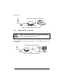
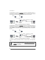
2.3.1
RS232 Interface Connection
This connection can be activated by simply inserting the 9-pin STARModem™
cable in the PC COM port.
Figure 12 - RS232 Interface Connection
2.3.2
CAUTION
Pen Emulation Interface Connection
Before proceeding with this connection, configure STARModem™
software parameters through the RS232 interface and then set the
hardware jumper position (see Chapter 3).
For Pen Emulation interface connection, it is necessary to use the adapter as shown
in the following figure.
9
STARModem™
Datalogic Standard Pen Emulation Cable
90ACC1859
STARModem™ Adapter
Figure 13 - Pen Emulation Interface Connection
2.3.3
CAUTION
Wedge Interface Connection
Before proceeding with this connection, configure STARModem™
software parameters through the RS232 interface and then set the
hardware jumper position (see Chapter 3).
For Wedge interface connection, it is necessary to use the adapter as shown in the
following figure.
Datalogic Standard Wedge Cable
90ACC1859
STARModem™ Adapter
Figure 14 - Wedge Interface Connection
10
INTIAL SETUP
3
INITIAL SETUP
For a correct STARModem™ configuration keep in mind the following guidelines:
•
when using the modem for the first time, set the desired STARModem™
address via RS232 serial interface, since its factory default address is
"Undefined";
•
for Wedge/Pen Emulation interface connections, set all parameters via RS232
interface either using DL Sm@rtSet or sending configuration strings to
STARModem™. Then, set the correct hardware jumper position as indicated in
the table given in par. 3.2.1 under "Interface Selection".
For changing any configuration parameter in Wedge/Pen Emulation interface
connections, send the new configuration commands via radio using Datalogic RF
devices (refer to “STARModem™ Configuration Using Barcodes” document
provided on the CD-ROM). Otherwise, set the jumper in the RS232 position
(RS232 communication parameters are set to default values) to send the
configuration strings to STARModem™ via serial interface and set the jumper
back in Wedge/Pen Emulation position to enable this kind of connection.
For jumper setting, open the antenna support by means of the 2 screws as
shown in the following figure:
Screws
Position 2
Position 1
Figure 15 - Jumper Positioning
Position 1 = RS232/Digital interface
Position 2 = Wedge/Pen Emulation interface
11
STARModem™
3.1
DEFINING THE SETUP
For STARModem™ two different setups are provided to select communication
either in Stand Alone mode or in STAR-System™ mode.
Proceed as shown in the following diagram:
Begin Setup by choosing the setup
procedure for your STARModem™
as indicated below.
STARModem™
STARModem™
Communication in
Stand Alone mode
Communication in
STAR-System™ mode
Par. 3.2
Par. 3.3
End of Setup
Your modem is now ready to
communicate using the default settings.
12
INTIAL SETUP
3.1.1
Configuration Strings
STARModem™ initial setup must be performed via serial interface by sending the
configuration strings to the modem using any terminal emulation program, for
example Hyper Terminal.
Ensure that your PC COM port is set as follows:
9600 baud, no parity, 8 data bits, 1 stop bit, handshaking disabled.
NOTE
The programming sequence is the following:
$+
$-
Command
CR
Carriage return character (0D Hex.)
Exit and Save configuration
Character sequence in following tables
Enter configuration environment
Example
Command programming sequence:
$+
MA0RC1237
$-
CR
Carriage return character (0D Hex.)
Exit and Save configuration
STAR-Modem address in Stand Alone system: 1237
Enter configuration environment
13
STARModem™
3.2
3.2.1
SETUP FOR STAND ALONE MODE
STARModem™ Receiver (Server)
RESTORE DEFAULT
Whenever necessary, send the following string to STARModem™ via RS232 to
restore its default values. Otherwise skip to step 2:
1.
$+$*CR
Restore STARModem™ Default
This command does not change the STARModem™ address nor the RF Baud
Rate parameters.
SET RADIO ADDRESS
Follow the procedure below to set the STARModem™ radio address and prepare it
to receive data from the RF devices of the system.
2.
Enter Configuration
3.
Set STARModem™ Radio Address
xxxx = four digits for the STARModem™ address (from
0000 to 1999). This address must be unique.
4.
Set RF Baud Rate (not for USA model)
x = 0 defines 9600 baud
1 defines 19200 baud
MFx
5.
Exit and Save Configuration
$-CR
$+
MA0RCxxxx
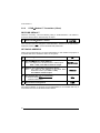
INTERFACE SELECTION
6.
14
Select the desired interface string for your application, then set the correct
hardware jumper position.
Among the following interface selection strings, send only the string that
suits your application:
Jumper
Position
RS232 Interface
$+CP0$-CR
1
Pen Emulation Interface
$+CP6$-CR
2
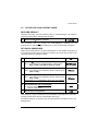
INTIAL SETUP
Wedge Interface
IBM AT or PS/2 PCs
$+CP500$-CR
2
IBM XT
$+CP503$-CR
2
PC Notebook
$+CP505$-CR
2
IBM SURE1
$+CP506$-CR
2
IBM Terminal 3153
$+CP504$-CR
2
IBM Terminals 31xx, 32xx, 34xx, 37xx
To select the interface for these IBM Terminals, send the correct KEY TRANSMISSION
string. Select the KEYBOARD TYPE if necessary (default = advanced keyboard).
Make-only keyboard
$+CP502$-CR
2
Make-break keyboard
$+CP501$-CR
2
Advanced keyboard
$+FK1$-CR
2
Typewriter keyboard
$+FK0$-CR
2
ALT MODE
The ALT-mode selection allows barcodes sent to the PC to be interpreted correctly
independently from the Keyboard Nationality used. You do not need to make a
Keyboard Nationality selection.
(default = Num Lock Unchanged).
Make sure the Num Lock key on your keyboard is ON.
IBM AT- ALT mode
$+CP507$-CR
2
PC Notebook - ALT mode
$+CP508$-CR
2
Wyse Terminal - ANSI Keyboard
$+CP509$-CR
2
Wyse Terminal - PC Keyboard
$+CP510$-CR
2
Wyse Terminal - ASCII Keyboard
$+CP511$-CR
2
Wyse Terminal - VT2200 style Keyboard
$+CP514$-CR
2
APPLE ADB Bus
$+CP513$-CR
2
Digital Terminal VT2xx/3xx/4xx
$+CP512$-CR
1
CAUTION
For changing the configuration parameters when using the Digital
terminal interface, send the new values via radio through
Datalogic RF devices. Otherwise, send the $+CP0$-CR string via
radio to set the RS232 interface and define the parameters via
serial interface. This operation sets the RS232 parameters to
default values and erases the current header and terminator
selection. Thus, after configuration setting, you must restore the
Digital Terminal interface, Header and Terminator selection by
sending a command string similar to the one given in the
following example:
$+CP512EA0141EA1102$-CR.
15
STARModem™
3.2.2
STARModem™ Transmitter (Client)
RESTORE DEFAULT
Whenever necessary, send the following string to STARModem™ via RS232 to
restore its default values. Otherwise skip to step 2:
1.
Restore STARModem™ Default
$+$*CR
This command does not change the STARModem™ address nor the Stand Alone
destination device address, nor the RF Baud Rate parameters.
SET RADIO ADDRESS
Follow the procedure below to set the STARModem™ radio address and prepare it
to transmit data to the destination device of the system.
2.
Enter Configuration
3.
Set STARModem™ Radio Address
xxxx = four digits for the STARModem™ address (from
0000 to 1999). This address must be unique.
4.
Address of the Stand Alone Destination Device
xxxx = four digits for the address of the Stand Alone
Destination Device (from 0000 to 1999).
This address must be unique.
$+
MA0RCxxxx
MSxxxx
5.
Set RF Baud Rate (not for USA model)
x = 0 defines 9600 baud
1 defines 19200 baud
MFx
6.
Exit and Save Configuration
$-CR
No interface selection is required, since STARModem™ can transmit data only if
connected to the Host via its RS232 serial interface.
16
INTIAL SETUP
3.3
SETUP FOR STAR-SYSTEM™ MODE
RESTORE DEFAULT
Whenever necessary, send the following string to STARModem™ via RS232 to
restore its default values. Otherwise skip to step 2:
1.
Restore STARModem™ Default
$+$*CR
This command does not change the STARModem™ address nor the
STAR-System™ destination device addresses, nor the RF Baud Rate parameters.
SET RADIO ADDRESSES
Follow the procedure below to set the STARModem™ radio address and prepare it
to receive and transmit data to all devices included in the range from the First to the
Last STAR-System™ destination device.
2.
Enter Configuration
3.
Set STARModem™ Radio Address
xxxx = four digits for the STARModem™ address (from
0000 to 1999). This address must be unique.
4.
First STAR-System™ Destination Device Address
xxxx = four digits for the Destination Device address (from
0000 to 1999).
MSxxxx
5.
Last STAR-System™ Destination Device Address
xxxx = four digits for the Destination Device address (from
0000 to 1999).
If transmitting to one Destination device only, this selection
is not required.
MTxxxx
$+
MA1RCxxxx
6.
Set RF Baud Rate (not for USA model)
x = 0 defines 9600 baud
1 defines 19200 baud
MFx
7.
Exit and Save Configuration
$-CR
When defining a range of destination device addresses, STARModem™ activates
roaming towards all the devices included within this range.
No interface selection is required, since all STAR-System™ transactions occur via
serial interface.
17
STARModem™
4
CONFIGURATION
Once the modem is setup, you can change the default parameters to meet your
application needs by sending the desired strings to the modem via serial interface.
Refer to chapter 3 for initial configuration in order to set the default values and if
necessary select the interface for your application.
The following table lists all configuration commands which do not require the $character:
Description
String
Enter Configuration
$+
Exit and Save Configuration
$-
Restore Default
$+$*CR
Transmit Software Release
$+$!CR
Transmit Configuration
$+$&CR
NOTE
18
It is always possible to activate the modem in temporary mode by
pressing the “s” (lower case) key on the keyboard and connecting
simultaneously an external power supply to the power jack provided
on the modem 9-pin cable connector. When working in temporary
mode, you can get the modem current configuration and its software
release. Furthermore, it is possible to send a command string starting
with the $+ characters and terminating with the $- characters. To exit
the temporary mode simply reset STARModem™.
The communication parameters must be set to 9600 baud, no parity,
8 data bits, 1 stop bit, handshaking disabled.
CONFIGURATION
In this manual, the configuration parameters are divided into logical groups making it
easy to find the desired function based on its reference group.
The first three groups are for Standard Interface parameter configuration:
•
RS232
•
WEDGE
•
PEN EMULATION
The following parameter groups are common to all interface applications:
DATA FORMAT parameters regard the messages sent to the Host system for all
interfaces except Pen Emulation.
RADIO PARAMETERS allow configuration of radio protocol parameters.
NOTE
It is strongly recommended to read par. 5.1 in Radio and Serial
Communication controls and the example applications in appendix A
for correct parameter settings.
19
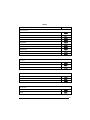
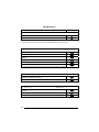
RS232 PARAMETERS
BAUD RATE
PARITY
DATA BITS
STOP BITS
HANDSHAKING
ACK/NACK PROTOCOL
FIFO
INTER-CHARACTER DELAY
RX TIMEOUT
FRAME PACKING
~
~
~
~
~
~
~
~
~
~
~
~
~
~
~
~
~
~
~
~
The programming sequence is the following:
$+
Command
$-
CR
Carriage return character (0D Hex.)
Exit and Save configuration
Character sequence in following tables
Enter configuration environment
20
RS232
Description
String
BAUD RATE
150 baud
CD0
300 baud
CD1
600 baud
CD2
1200 baud
CD3
2400 baud
CD4
4800 baud
CD5
9600 baud
CD6
19200 baud
CD7
38400 baud
CD8
57600 baud
CD9
PARITY
None
CC0
Even parity
CC1
Odd parity
CC2
DATA BITS
7 bits
CA0
8 bits
CA1
9 bits
CA2
STOP BITS
1 bit
CB0
2 bits
CB1
21
RS232
Description
HANDSHAKING
String
see par. 5.2.1
Disable
CE0
Hardware (RTS/CTS)
CE1
Software (XON/XOFF)
CE2
RTS always ON
CE3
Modem (RTS/CTS)
CE4
ACK/NACK PROTOCOL
see par. 5.2.2
Disabled
ER0
Enable ACK/NACK
ER1
Enable DATA/NACK
ER2
FIFO
see par. 5.2.4
Disable
ME1
Enable
ME0
INTER-CHARACTER DELAY
CK00 – CK99
Inter-character delay (ms)
RX TIMEOUT
see par. 5.2.3 and par. 5.2.5
CL00 – CL99
RX Timeout (sec)
FRAME PACKING
see par. 5.2.5
Frame + [CR]
ML0
[STX] + Len + frame + [CR]
ML1
Frame after timeout
ML2
22
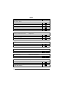
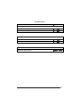
WEDGE PARAMETERS
~
~
KEYBOARD NATIONALITY
CAPS LOCK
NUM LOCK
STOP BITS
INTER-CHARACTER DELAY
INTER-CODE DELAY
KEYBOARD SETTING
~
WEDGE CONTROL CHARACTER
EMULATION
~
~
~
~
~
~
~
~
~
~
~
~
~
The programming sequence is the following:
$+
Command
$-
CR
Carriage return character (0D Hex.)
Exit and Save configuration
Character sequence in following tables
Enter configuration environment
23
WEDGE
Description
String
KEYBOARD NATIONALITY
Belgian
FJ7
English
FJ4
French
FJ2
German
FJ3
Italian
FJ1
Spanish
FJ6
Swedish
FJ5
USA
FJ0
CAPS LOCK
Caps lock ON
FE1
Caps Lock OFF
FE0
Select the appropriate code to match your keyboard caps lock status.
Note: For PC Notebook interface selections, the caps lock status is automatically recognized,
therefore this command is not necessary.
NUM LOCK
Toggle Num Lock
FL1
Num Lock Unchanged
FL0
This selection is used together with the Alt Mode interface selection for AT or Notebook PCs.
It changes the way the Alt Mode procedure is executed, therefore it should be set as follows:
•
•
if your keyboard Num Lock is normally on use num lock unchanged
if your keyboard Num Lock is normally off use toggle num lock
In this way the device will execute the Alt Mode procedure correctly for your application.
INTER-CHARACTER DELAY
Inter-character delay (ms)
24
CK00 – CK99
WEDGE
KEYBOARD SETTING
ALPHANUMERIC KEYBOARD SETTING
The reader can be used with terminals or PCs with various keyboard types and nationalities
through a simple keyboard setting procedure.
The type of computer or terminal must be selected before activating the keyboard setting
command.
Keyboard setting consists of communicating to the reader how to send data corresponding to
the keyboard used in the application. The keys must be set in a specific order.
Press and release a key to set it.
Some characters may require more than one key pressed simultaneously during normal use
(refer to the manual of your PC or terminal for keyboard use). The exact sequence must be
indicated to the reader in this case pressing and releasing the different keys.
Example:
If one has to press the "Shift" and "4" keys simultaneously on the keyboard to transmit the
character "$" to the video, to set the "$", press and release "Shift" then press and release "4".
Each pressed and released key generate a yellow LED on the device, otherwise repress the
key. Never press more than one key at the same time, even if this corresponds to the normal
use of your keyboard.
Press "Backspace" to correct a wrong key entry.
Note: "CAPS LOCK" and "NUM LOCK" must be off before starting the keyboard setting
procedure. "SHIFT" must be repressed for each character and cannot be substituted by
"CAPS LOCK".
setting the alphanumeric keyboard
i'#1k
i'#1k
i'#1k
Read the code above with one of the RF devices compatible with STARModem™ and send it
to the modem via radio.
press the keys shown in the following table according to their numerical order.
Some ASCII characters may be missing as this depends on the type of keyboard: these are
generally particular characters relative to the various national symbologies. In this case:
•
The first 4 characters (Shift, Alt, Ctrl, and Backspace) can only be substituted with
keys not used, or substituted with each other.
•
characters can be substituted with other single symbols (e.g. "SPACE") even if not
included in the string set used.
•
characters can be substituted with others corresponding to your keyboard.
25
WEDGE
01 : Shift
02 : Alt
03 : Ctrl
04 : Backspace
05 : SPACE
06 : !
07 : "
08 : #
09 : $
10 : %
11 : &
12 : '
13 : (
14 : )
15 : *
16 : +
17 : ,
18 : 19 : .
20 : /
21 : 0
22 : 1
23 : 2
24 : 3
25 : 4
26 : 5
27 : 6
28 : 7
29 : 8
30 : 9
31 : :
32 : ;
33 : <
34 : =
35 : >
36 : ?
37 : @
38 : A
39 : B
40 : C
41 : D
42 : E
43 : F
44 : G
45 : H
46 : I
47 : J
48 : K
49 : L
50 : M
51 : N
52 : O
53 : P
54 : Q
55 : R
56 : S
57 : T
58 : U
59 : V
60 : W
61 : X
62 : Y
63 : Z
64 : [
65 : \
66 : ]
67 : ^
68 : _ (underscore)
69 : `
70 : {
71 : |
72 : }
73 : ~
74 : DEL
During the keyboard setting the red LED on the modem always blinks, the yellow LED stays on
and blinks off only each time a key is pressed, while the green LED stays on and blinks off only
each time the Backspace key is pressed. Once the last key has been pressed, the yellow LED
stays off indicating the keys have been registered, while the green LED stays on again. Read
the code below and send it to the modem via radio to end the procedure.
ending the procedure
i
i
i
Description
k
k
k
String
INTER-CODE DELAY
Inter-code delay (ms)
FG00 – FG99
CONTROL CHARACTER EMULATION
Ctrl + Shift + Key
FO0
Ctrl + Key
FO1
26
PEN EMULATION
~
~
~
~
~
~
~
OPERATING MODE
MINIMUM OUTPUT PULSE
CONVERSION TO CODE 39 AND CODE 128
OVERFLOW
OUTPUT LEVEL
IDLE LEVEL
INTER-BLOCK DELAY
~
~
~
~
~
~
~
The programming sequence is the following:
$+
Command
$-
CR
Carriage return character (0D Hex.)
Exit and Save configuration
Character sequence in following tables
Enter configuration environment
27
PEN EMULATION
Description
String
OPERATING MODE
Interpret mode (does not require $+ or $-)
$]
Transparent mode (does not require $+ or $-)
$[
Interpret mode: interprets commands without sending them to the decoder.
Transparent mode: sends commands to the decoder without interpreting them.
MINIMUM OUTPUT PULSE
see par. 5.3.1
200 µs
DG0
400 µs
DG1
600 µs
DG2
800 µs
DG3
1 ms
DG4
1.2 ms
DG5
A higher parameter value corresponds to a lower code resolution emulation.
CONVERSION TO CODE 39 AND CODE 128
see par. 5.3.3
Enable conversion to Code 39
DA1
Enable conversion to Code 128
DA2
OVERFLOW
see par. 5.3.2
Narrow
DH0
Medium
DH1
Wide
DH2
28
PEN EMULATION
Description
OUTPUT LEVEL
String
see par. 5.3.4
Normal (white = logic level 0)
DD0
Inverted (white = logic level 1)
DD1
IDLE LEVEL
see par. 5.3.4
Normal (black level)
DE0
Inverted (white level)
DE1
INTER-BLOCK DELAY
Inter-block delay (100 ms)
see par. 5.3.5
CK00 – CK99
29
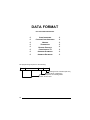
DATA FORMAT
NOT FOR PEN INTERFACES
CODE IDENTIFIER
CUSTOM CODE IDENTIFIER
HEADER
TERMINATOR
HEADER POSITION
CODE LENGTH TX
ADDRESS STAMPING
ADDRESS DELIMITER
~
~
~
~
~
~
~
~
~
~
~
~
~
~
~
~
The programming sequence is the following:
$+
Command
$-
CR
Carriage return character (0D Hex.)
Exit and Save configuration
Character sequence in following tables
Enter configuration environment
30
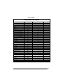
DATA FORMAT
CODE IDENTIFIER TABLE
CODE
2/5 interleaved
2/5 industrial
2/5 normal 5 bars
2/5 matrix 3 bars
EAN 8
EAN 13
UPC A
UPC E
EAN 8 with 2 ADD ON
EAN 8 with 5 ADD ON
EAN 13 with 2 ADD ON
EAN 13 with 5 ADD ON
UPC A with 2 ADD ON
UPC A with 5 ADD ON
UPC E with 2 ADD ON
UPC E with 5 ADD ON
Code 39
Code 39 Full ASCII
CODABAR
ABC CODABAR
Code 128
EAN 128
ISBT 128
Code 93
CIP/39
CIP/HR
Code 32
Codablock-A
Codablock-F Std
Codablock-F EAN
MSI
Plessey Standard
Plessey Anker
Telepen
Delta IBM
Code 11
Code 16K
Code 49
PDF417
AIM STANDARD
]Iy
]Xy
]Sy
]Xy
]E4
]E0
]Xy
]Xy
]E5
]E6
]E1
]E2
]Xy
]Xy
]Xy
]Xy
]Ay
]Ay
]Fy
]Xy
]Cy
]Cy
] C4
]Gy
]Xy
]Xy
]Xy
]O6
]O4
]O5
]My
]P0
]P1
]X0
]X0
]Hy
]K0
]Ty
]L0
DATALOGIC STANDARD
Custom
N
P
O
Q
A
B
C
D
J
K
L
M
F
G
H
I
V
W
R
S
T
k
f
U
Y
e
X
n
l
m
Z
a
o
d
c
b
p
q
r
31
DATA FORMAT
•
AIM standard identifiers are not defined for all codes: the X identifier is assigned to the
code for which the standard is not defined. The y value depends on the selected options
(check digit tested or not, check digit tx or not, etc.).
•
When customizing the Datalogic Standard code identifiers, 1 or 2 identifier characters can
be defined for each code type. If only 1 identifier character is required, the second
character must be selected as FF (disabled).
•
The code identifier can be singly disabled for any code by simply selecting FF as the first
identifier character.
Write in the Custom character identifiers in the table above for your records.
Description
String
CODE IDENTIFIER
Disable
EB0
Datalogic standard
EB1
AIM standard
EB2
Custom
EB3
CUSTOM CODE IDENTIFIER
EHabc
Custom code identifier
a = ASCII character.
b, c =
HEX values representing an ASCII character.
a = ASCII character of the DATALOGIC STANDARD Code Identifier from the table on
previous page.
b = Hex value of the first Custom Code Identifier character from 00 to FE in Appendix B;
FF = disable Code Identifier
c = Hex value of the second Custom Code Identifier character from 00 to FE in Appendix B;
FF = disable second character of Custom Code Identifier
Example: Code 39 Code Identifier = @
Custom Code Identifier
EH
32
Code 39
+
V
@
+
40
Disable second chracter
+
FF
DATA FORMAT
Description
String
HEADER
EA00
No header
One character header
EA01x
Two character header
EA02xx
Three character header
EA03xxx
Four character header
EA04xxxx
Five character header
EA05xxxxx
Six character header
EA06xxxxxx
Seven character header
EA07xxxxxxx
Eight character header
EA08xxxxxxxx
TERMINATOR
EA10
No terminator
One terminator header
EA11x
Two terminator header
EA12xx
Three terminator header
EA13xxx
Four terminator header
EA14xxxx
Five terminator header
EA15xxxxx
Six terminator header
EA16xxxxxx
Seven terminator header
EA17xxxxxxx
Eight terminator header
EA18xxxxxxxx
x=
HEX values representing an ASCII character.
x = HEX value from 00 to FE in Appendix B.
Example: Header = AB
Two character header
EA02
A
+
41
B
+
42
Example: Terminator = CR LF
Two character terminator
EA12
CR
+
0D
LF
+
0A
For more details about default and WEDGE Interface Extended Keyboard values, see par. 5.4.1.
33
DATA FORMAT
Description
HEADER POSITION
String
see par. 0
First frame field
ES0
Before message field
ES1
CODE LENGTH TX
Code length not transmitted
EE0
Code length transmitted in variable-digit length
EE1
Code length transmitted in fixed 4-digit format
EE2
The code length is transmitted in the message after the Headers and Code Identifier
characters.
The code length is calculated after performing any field adjustment operations.
ADDRESS STAMPING
see par. 5.4.2
Disable
RU0
Enable
RU1
ADDRESS DELIMITER
see par. 5.4.3
Disable
RV0
Enable
RV1a
a = a Hex value representing the ASCII character in the range from 00 to FE in Appendix B.
34
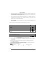
RADIO PARAMETERS
RF BAUD RATE
TRANSMISSION MODE
RADIO PROTOCOL TIMEOUT
SINGLE STORE
ACK/NACK FROM REMOTE
HOST
BEACON
~
~
~
~
~
~
~
~
~
~
~
~
The programming sequence is the following:
$+
Command
$-
CR
Carriage return character (0D Hex.)
Exit and Save configuration
Character sequence in following tables
Enter configuration environment
35
RADIO PARAMETERS
Description
RF BAUD RATE (not for USA model)
String
see par. 5.5.1
9600 baud
MF0
19200 baud
MF1
TRANSMISSION MODE (Client only)
see par. 5.5.2
1 way mode
MW0
2 way mode
MW1
RADIO PROTOCOL TIMEOUT (Client only)
see par. 5.5.3
MH01 – MH19
Radio protocol timeout (seconds)
SINGLE STORE (Client only)
see par. 5.5.4
Disable
MO0
One attempt
MO1
Two attempts
MO2
Three attempts
MO3
Four attempts
MO4
Five attempts
MO5
Six attempts
MO6
Seven attempts
MO7
Eight attempts
MO8
Continuous
MO9
36
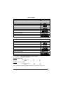
RADIO PARAMETERS
Description
String
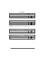
ACK/NACK FROM REMOTE HOST (Client only)
see par. 5.5.5
Disabled
MR0
Enable ACK/DATA/NACK
MR1
BEACON (Client only)
see par. 5.5.6
Disabled
MB0
Beacon every 2 seconds
MB1
Beacon every 3 seconds
MB2
Beacon every 4 seconds
MB3
Beacon every 5 seconds
MB4
Beacon every 6 seconds
MB5
Beacon every 8 seconds
MB6
Beacon every 10 seconds
MB7
Beacon every 20 seconds
MB8
Beacon every 30 seconds
MB9
37
STARModem™
5
REFERENCES
5.1
RADIO AND SERIAL COMMUNICATION CONTROLS
STARModem™ communication (both radio and serial) can be controlled by several
parameters depending on whether it is a Client or Server. STARModem™ can act
as both Client and Server in each of the Stand Alone and STAR-System™ Modes.
In the STAR-System™ Mode, bi-directional communication means that
STARModem™ can dynamically switch from being Client to Server and vice versa.
The following table summarizes which parameters are controlled by the Client and
which ones are controlled by the Server.
Client (Transmitter)
controlled parameters:
Transmission Mode
ACK/NACK From Remote Host
FIFO
Handshaking
Single Store
NOTE
38
Server (Receiver)
controlled parameters
ACK/NACK Protocol
Handshaking
To avoid incorrect interpretation of ACK characters, ACK/NACK
Protocol and ACK/NACK from Remote Host cannot be
simultaneously enabled on the same STARModem™.
REFERENCES
To help understand the various communication control possibilities among the
different communication modes, we will analyze the communication control
parameter settings for the following 4 cases:
1) STARModem™ in Stand Alone Mode acting as Server (like an OM-cradle)
2) STARModem™ in Stand Alone Mode acting as Client (like an RF device)
3) STARModem™ in STAR-System™ Mode
4) STARModem™ in Stand Alone Mode acting as Server (for an intelligent printer)
Case 1 – STARModem™ in Stand Alone Mode as Server (like an OM-cradle)
DRAGON 1
DRAGON 2
Modem
DRAGON 3
HOST
F734-E
Figure 16 – Stand Alone Mode with STARModem™ Server
STARModem™ is in Stand Alone Mode as a dedicated Server receiving (like an
OM-cradle). The ACK/NACK Protocol parameter can be set to assure correct
communication between STARModem™ and the local Host.
Assuming the RF devices are setup for 2 way transmission we can analyze the
following ACK/NACK protocol selections:
RF devices - Transmission Mode = 2 ways
The Host must respond to a 2 way transmission
•
If Modem - ACK/NACK = disabled
there is no control of the communication between STARModem™ and the
Local Host. STARModem™ answers the RF device which initiated the 2 way
transaction with DATA received from the Local Host.
39
STARModem™
•
If Modem - ACK/NACK = enabled
when the Local Host receives a message correctly, it answers STARModem™
with the ACK character. Only then does STARModem™ acknowledge the RF
device which initiated the 2 way transaction with an Empty Answer.
•
Modem - DATA/NACK = enabled
when the Local Host receives a message correctly, it answers STARModem™
with DATA. STARModem™ then answers the RF device which initiated the 2
way transaction with this DATA (i.e. command to RF device display).
Case 2 – STARModem™ in Stand Alone Mode as Client (like an RF device)
1
2
Figure 17 – Stand Alone Mode with STARModem™ 2 Client
In the figure above, STARModem™ 2 is in Stand Alone Mode as a dedicated
Client (as an RF device). The following parameters may be set depending on the
application:
Modem 1 - ACK/NACK = enabled
Scanner - Handshaking= RTS/CTS
•
If Modem 2 -
Transmission Mode = 1 way
ACK/NACK from Remote Host = disabled
FIFO = disabled
Handshaking = Modem (RTS/CTS)
In this case, Modem 2 sends data (messages) to the Remote Host. The special
case of FIFO disabled blocks transmission of the scanner until an
acknowledgement is received from Modem 1. Because ACK/NACK is enabled
for Modem 1, only after Modem 1 has received an ACK from the Remote Host
does it acknowledge reception (Empty Answer to Modem 2).
40
REFERENCES
Case 3 – STARModem™ in STAR-System™ Mode
Client
Server
Modem 1
Modem 2
HOST 1
HOST 2
Figure 18 – STAR-System™ Mode
Both STARModems™ are in STAR-System™ Mode and are therefore able to
communicate bi-directionally. For analysis purposes only, we assume the situation
where Host 1 is Client and Host 2 is Server. It is clear that the situation is analogous
in the opposite direction:
•
If Modem 1 -
Transmission Mode = 1 way
ACK/NACK from Remote Host = disabled
FIFO = enabled
Handshaking = any
The Client, (Host 1) sends a message to the Remote Host (Host 2), but no
control exists upon reception and even if ACK/NACK Protocol is implemented on
the Server side (Remote Host), no answer is returned from Modem 2 to Modem
1 (except for a single blink from the red LED on Modem 1 if radio transaction has
failed). This is not a secure communication.
•
If Modem 1 -
Transmission Mode = 1 way
ACK/NACK from Remote Host = enabled
FIFO = enabled
Handshaking = any
The Client, (Host 1) sends a message to the Remote Host (Host 2). Modem 2
acknowledges good radio reception but no control is made on Remote Host
reception. If Modem 2 acknowledges radio reception within the Radio Protocol
Timeout, Modem 1 sends ACK to its local Host, otherwise it sends NACK.
41
STARModem™
•
If Modem 1 -
Transmission Mode = 2 ways
ACK/NACK from Remote Host = enabled
FIFO = enabled
Handshaking = any
Single Store = enabled
The Client, (Host 1) sends a message to the Remote Host (Host 2) and expects
an answer from Host 2. Host 2 answers with DATA (a string of up to 238
characters). If Modem 2 sends this DATA answer within the Radio Protocol
Timeout, Modem 1 sends it to its local Host (Host 1), otherwise Modem 1 sends
NACK. In addition, the Single Store parameter upon Radio Protocol timeout,
causes Modem 1 to retry transmission of the same message the defined number
of times, before responding to its local Host (Host 1) with NACK.
Host 1 •
Handshaking = RTS/CTS
If Modem 1 -
Transmission Mode = any
ACK/NACK from Remote Host = enabled
FIFO = disabled
Handshaking = Modem (RTS/CTS)
The Client, (Host 1) sends a message to the Remote Host (Host 2). Modem 1
after receiving the message, blocks transmission of Host 1 until communication
is completed according to the other communication control parameter settings as
described above.
NOTE
NOTE
42
The most secure settings for bi-directional communication in
STAR-System™ Mode is to have ACK/NACK from Remote Host
enabled and Two-way transmission at both ends. In addition, in case
the first transmission fails, the Single Store parameter automatically
repeats transmission of the same data packet up to the number of
specified attempts.
When STARModem™ acts as Client and STARGATE™ acts as
Server, FIFO disabled only works if two-way transmission mode is
set.
REFERENCES
Case 4 – STARModem™ in Stand Alone Mode as Server (for an intelligent
printer)
Client
Server
Modem 1
Modem 2
Printer
HOST 1
Figure 19 – Stand Alone Mode with STARModem™ 2 Server
The two STARModems™ in this case can be configured in Stand Alone Mode,
however this limits one to be the dedicated Client and the other to be the dedicated
Server. Bi-directional communication is not possible in Stand Alone modes.
Assuming that Host 1 is Client we can analyze the following transmission parameters
from both STARModem™ 1 and STARModem™ 2’s point of view :
Modem 1 Client
Transmission Mode = 2 way
ACK/NACK from Remote Host = enabled
FIFO = enabled
Handshaking = any
The Client, (Host 1) sends a message to the Remote Host (Printer) and expects
an answer from the Printer. If the answer doesn’t arrive before Radio Protocol
Timeout, Modem 1 sends NACK to the Local Host.
•
If Modem 2 Server
ACK/NACK Protocol = enabled as ACK/NACK
When STARModem™ 2 receives a new message, it sends it to the Printer.
The Printer answers with ACK. If Modem 2 acknowledges within the Radio
Protocol Timeout, Modem 1 sends an Empty Answer to its Local Host (Host 1),
otherwise it sends NACK.
•
If Modem 2 Server
ACK/NACK Protocol = enabled as DATA/NACK
When STARModem™ 2 receives a new message, it sends it to the Printer.
The Printer answers with DATA (a string of up to 238 characters). If Modem 2
sends this DATA answer within the Radio Protocol Timeout, Modem 1 sends it to
its local Host (Host 1), otherwise Modem 1 sends NACK.
43
STARModem™
5.2
5.2.1
RS232 PARAMETERS
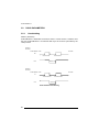
Handshaking
Modem: (RTS/CTS)
STARModem™ deactivates the RTS line when it cannot receive a character from
the Host. STARModem™ can transmit data only if the CTS line (controlled by the
Host) is active.
Signals at
EIA levels
STARModem™ Side
Host Side
RX
Received data
RTS
Received data
Modem busy
Signals at
EIA levels
STARModem™ Side
Host Side
TX
Transmitted data
CTS
Transmitted data
Host busy
RTS/CTS Modem Handshaking
44
REFERENCES
Hardware handshaking: (RTS/CTS)
The RTS line is activated by STARModem™ before transmitting a character.
Transmission is possible only if the CTS line (controlled by the Host) is active.
Signals at
EIA levels
RTS
TX
Transmitted data
Transmitted data
Host busy
CTS
RTS/CTS Handshaking
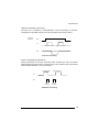
Software handshaking: (XON/XOFF)
During transmission, if the Host sends the XOFF character (13 Hex), the modem
interrupts the transmission with a maximum delay of one character and only resumes
when the XON character (11 Hex) is received.
Transmitted data
Transmitted data
TX
RX
XOFF
Host busy
XON
Host ready
XON/XOFF handshaking
45
STARModem™
5.2.2
ACK/NACK Protocol
This parameter sets a transmission protocol which takes place between
STARModem™ (Server) and Local Host in RS232. An RF device (such as a handheld reader) passes its data (code read) to the modem which sends it to the Host.
The Host sends an ACK character (06 HEX) to the modem in the case of good
reception; a NACK character (15 HEX) requesting re-transmission is sent to the
modem in case of bad reception.
In the particular case where the RF device is configured for 2 way transmission and
therefore requires an answer, it is advised to set STARModem™ with the
DATA/NACK protocol. The DATA answer from the Local Host is implicitly considered
an ACK and is sent to the RF device. If instead ACK/NACK is used, the modem
generates an Empty Answer to the RF device.
Before selecting this parameter ensure that “ACK/NACK from
Remote Host” is disabled (see par. 5.5.5).
CAUTION
data
data
Server
ACK/NACK Disabled
data
data
Server
ACK or NACK
ACK/NACK Enabled
data
data
Server
DATA or NACK
DATA/NACK Enabled
46
REFERENCES
If the modem does not receive an ACK, DATA or NACK, transmission is ended after
the RX Timeout (see par. 5.2.3 ). See also Radio Protocol Timeout, par. 5.5.3, for
radio transmission to RF devices.
For ACK/NACK selection when STARModem™ as Client, is transmitting to a
destination device connected to a Remote Host refer to par. 5.1.
5.2.3
RX Timeout
This parameter can be used to automatically end data reception from the Local Host
after the specified period of time.
If no character is received from the Local Host, after the timeout expires, any
incomplete string is flushed from the modem buffer.
Refer to par. 5.2.5 for RX Timeout functioning when defining the frame packing.
5.2.4
FIFO
If enabled, the Destination Device collects all messages sent by STARModem™
and sends them in the order of acquisition to the connected Remote Host.
If disabled, STARModem™ blocks the message transmission from the Local Host
until an answer signaling the right/wrong message transmission has been received
from the Destination Device (1 way) or the Remote Host (2 way). Once the answer
has been received, the Local Host is allowed to send a new message.
This command requires the Modem (RTS/CTS) handshaking to be enabled.
For more details about the Transmission Mode refer to par. 5.5.2.
47
STARModem™
5.2.5
Frame Packing
This parameter defines the format of the frame to be transmitted between
STARModem™ and the Host.
The frame received by STARModem™ may contain a maximum of 238 characters.
All characters not included within this number will be transmitted from the Host in a
new frame.
Frame from Host to STARModem™
FRAME
Address
Address Delimiter
MESSAGE
The Address field has different meanings depending on if the FRAME is sent as a 2
way answer to an RF device, or if it is a new message that the STARModem™
Client sends to a destination device. See par. 5.4.2 for details.
Frame from STARModem™ to Host
FRAME
*Header
*Header
**Time-Stamp
Address
Address Delimiter
**Time-Stamp-Del
**Code Id
MESSAGE
Code Len
DATA
Terminator
*
There is only one header whose position can be defined through the related
parameter (see par. 0).
**
These are optional fields which can be configured depending on the type of RF
device used.
The Address field has different meanings depending on if the FRAME is a 2 way
answer to a previous 2 way transaction initiated by a STARModem™ Client, or if it
is a new message that an RF device sends to the STARModem™ Server. See par.
5.4.2 for details.
48
REFERENCES
Correct FRAME identification is managed by frame packing. Three different types of
frame packing can be selected:
•
Frame+ [CR] (default): the frame sent to STARModem™ is terminated by
[CR]. This means you cannot use the [CR] character within the frame.
In Frame + [CR] mode, make sure the FRAME does not contain [CR], nor begin
with $+ or #+ characters.
[CR]
FRAME
The frame transmitted by STARModem™ has no additional field. In this case
the end of the FRAME is either DATA or Terminator if any.
FRAME
•
[STX]+LEN+Frame+[CR]: both frames sent to and by STARModem™ are
preceded by [STX], LEN and terminated by [CR], where LEN is a field of 4 digits
and indicates the FRAME length in number of characters, that is FRAME +CR.
[STX]
LEN
FRAME
[CR]
The [STX], [CR] and [ESC] characters contained in the frame must be preceded
by the [ESC] character for a correct transmission.
•
Frame after Timeout: if the delay between two consecutive characters is more
than the selected timeout, the modem considers the frame completed. The
timeout corresponds to 1/10 of the value defined for RX Timeout (see par. 5.2.3).
Therefore, the timeout for frame packing is calculated in ms (from 10 ms to 990
ms).
NOTE
It is not possible to disable this timeout, therefore possible
values are in the range 10 - 990 ms. If RX Timeout is disabled,
Frame after Timeout is 10 ms.
Both the frames sent to and by STARModem™ have no additional fields:
FRAME
All commands to be sent using this frame packing must be preceded by the
string below, which substitutes the $+ character:
#+++PROG_REQ+++#
This string is always transmitted in a single frame preceding the one containing
the configuration command, as shown in the following examples:
49
STARModem™
Example 1
Sending the $+$![CR] command to transmit the modem software release:
1st Frame = #+++PROG_REQ+++#
nd
2 Frame = $![CR]
Example 2
Sending the $+ML0$-[CR] command to set the default frame packing
configuration:
st
1 Frame = #+++PROG_REQ+++#
nd
2 Frame = ML0$-[CR]
5.3
PEN EMULATION PARAMETERS
5.3.1
Minimum Output Pulse
This parameter sets the duration of the output pulse corresponding to the narrowest
element in the barcode. In this way the code resolution is controlled by the signal
sent to the decoder, independently from the physical resolution of the code read.
The shortest pulse (200 µs) corresponds to a high resolution code emulation and
therefore a shorter transfer speed to the decoder (for decoders able to work on high
resolution codes). Likewise, longer pulses correspond to low resolution code
emulation and therefore a longer transfer time to the decoder.
5.3.2
Overflow
This parameter generates a white space before the first bar and after the last bar of
the code. The selections are as follows:
narrow
= space 10 times the minimum output pulse.
medium
= space 20 times the minimum output pulse.
wide
= space 30 times the minimum output pulse.
5.3.3
Conversion to Code 39 and Code 128
This parameter allows converting the decoded codes into either Code 39 format or
Code 128 format. It is not possible to disable conversion.
50
REFERENCES
5.3.4
Output and Idle Levels
The following state diagrams describe the different output and idle level combinations
for Pen emulation:
idle
bar
OUTPUT: Normal
space
IDLE: Normal
black
white
barcode output
bar
OUTPUT: Normal
IDLE: Inverted
idle
space
black
white
barcode output
space
OUTPUT: Inverted
IDLE: Normal
white
idle
bar
black
barcode output
OUTPUT: Inverted
IDLE: Inverted
white
space
idle
bar
black
barcode output
Output and Idle Levels
5.3.5
Inter-Block Delay
For the PEN Emulation interface, data are sent to the Host in fixed size blocks of 20
characters each. The inter-block delay parameter allows setting a delay between
each block sent to the Host.
51
STARModem™
5.4
DATA FORMAT
5.4.1
Header/Terminator Selection
The header/terminator selection is not effected by restore default command. In fact,
header and terminator default values depend on the interface selection:
RS232:
no header, terminator CR-LF
WEDGE:
no header, terminator ENTER
These default values are always restored by sending the RS232 or WEDGE interface
selection string, see par. 3.1.1.
For the WEDGE interface, the following extended keyboard values can also be
configured:
EXTENDED KEYBOARD TO HEX CONVERSION TABLE
IBM AT
IBM 3153
APPLE ADB
IBM XT
IBM 31xx, 32xx,
34xx, 37xx
Wyse
Digital
HEX
KEY
KEY
KEY
KEY
83
84
85
86
87
88
89
8A
8B
8C
8D
8E
8F
90
91
92
93
94
95
96
97
98
99
9A
9B
ENTER
TAB
F1
F2
F3
F4
F5
F6
F7
F8
F9
F10
F11
F12
HOME
END
PG UP
PG DOWN
↑
↓
←
→
ESC
CTRL (Right)
Euro
ENTER
TAB
F1
F2
F3
F4
F5
F6
F7
F8
F9
F10
ESC
BACKSPACE
HOME
END
PG UP
PG DOWN
↑
↓
←
→
ESC
CTRL (Right)
Space
FIELD EXIT
TAB
F1
F2
F3
F4
F5
F6
F7
F8
F9
F10
F11
F12
ENTER
RESET
INSERT
DELETE
FIELD FIELD +
ENTER (Paddle)
PRINT
RETURN
TAB
F1
F2
F3
F4
F5
F6
F7
F8
F9
F10
F11
F12
F13
F14
F15
F16
UP
DOWN
LEFT
RIGHT
ESC
CTRL (Right)
Space
Space
For all devices using Wedge interface, all values from 9C to FE send the Space character
52
REFERENCES
SET CUSTOM EXTENDED HEADER/TERMINATOR KEYS
The extended Header/Terminator keys for Wedge Interface users can be
customized by defining them through a simple keyboard setting procedure.
For example, the Numeric Keypad keys can be set for use as Headers or
Terminators by substituting the default extended keys using this procedure.
The type of computer or terminal must be selected before activating the keyboard
setting command.
Press and release a key to set it.
Some characters may require more than one key pressed simultaneously during
normal use (refer to the manual of your PC or terminal for keyboard use). The exact
sequence must be indicated to the reader in this case pressing and releasing the
different keys.
Example:
If one has to press the "Shift" and "4" keys simultaneously on the keyboard to
transmit the character "$" to the video, to set the "$", press and release "Shift" then
press and release "4".
Each pressed and released key must generate a yellow LED blinking on the device,
otherwise repress the key. Never press more than one key at the same time, even if
this corresponds to the normal use of your keyboard.
Press "Back space" to correct a wrong key entry.
Note: "CAPS LOCK" and "NUM LOCK" must be off before starting the keyboard
setting procedure. "SHIFT" must be repressed for each character and cannot
be substituted by "CAPS LOCK".
Set Custom Extended Header/Terminator Keys
i'#6k
i'#6k
i'#
6k
Read the code above with one of the RF devices compatible with STARModem™ and send it
to the modem via radio.
•
•
If the first 4 KEYS (Shift, Alt, Ctrl, and Backspace) are not available on your
keyboard, you can only substitute them with keys not used, or substitute them with
each other.
Keys 5 to 28 must be defined
Press the desired keys in the following order:
53
STARModem™
CUSTOM EXTENDED KEYBOARD SETTING TABLE
Custom
Order
HEX
KEY
01
02
03
04
05
06
07
08
09
10
11
12
13
14
15
16
17
18
19
20
21
22
23
24
25
26
27
28
83
84
85
86
87
88
89
8A
8B
8C
8D
8E
8F
90
91
92
93
94
95
96
97
98
99
9A
Shift
Alt
Ctrl
Backspace
During the keyboard setting the red LED on the modem always blinks, the yellow
LED stays on and blinks off only each time a key is pressed, while the green LED
stays on and blinks off only each time the Backspace key is pressed. Once the last
key has been pressed, the yellow LED stays off indicating the keys have been
registered, while the green LED lights on again. Read the code below and send it to
the modem via radio to end the procedure.
ending the procedure
i
i
i
54
k
k
k
REFERENCES
Header Position
This parameter defines the header position within the frame to be transmitted from
STARModem™ to the Host. The header can be positioned in either the first field of
the frame or in the field preceding the message:
FRAME
HEADER
HEADER
Time-Stamp
Address
Time-Stamp-Del
Address Delimiter
Code Id
MESSAGE
Code Len
DATA
Terminator
The Address field has different meanings depending on if the FRAME is a 2 way
answer to a previous 2 way transaction initiated by a STARModem™ Client, or if it
is a new message that an RF device sends to the STARModem™ Server. See par.
5.4.2 for details.
5.4.2
Address Stamping
If enabled, this command includes the RF device or STARModem™ address in the
message/answer transmitted. It is advised to enable this parameter when
STARModem™ is a Server for more than one Client in 2 way transmission. In this
way the Host knows to which Client the answer must be sent.
If receiving data from an RF device working in 1 way mode, STARModem™ (Server)
automatically includes the RF device address in the message to be sent to the Host.
If receiving data from an RF device working in 2 way mode, STARModem™
(Server) automatically includes the RF device address in the message to be sent to
the Host. It is required to set the Host application to include the same address in the
answer to be transmitted back to the RF device.
message
RF Device
in 2 way mode
RF Dev. Addr + message
answer
Server
RF Dev. Addr + answer
Figure 20 - Receiving a Message from RF device in 2 Way Mode
55
STARModem™
If STARModem™ as Client, is transmitting to more than one destination device in 1
way mode, it is necessary to set the Host application to include the modem address
in the message to be transmitted to the destination devices of the system.
message
Modem Addr. + message
Destination
Device
Figure 21 - Transmitting a Message in 1 Way Mode
If STARModem™ as Client, is transmitting to more than one destination device in 2
way mode, it is necessary to set the Host application to include the modem address
in the message to be transmitted to the destination devices of the system.
STARModem™ will include the same address in the answer which sends back to
the Host.
message
Destination
Device
Modem Addr. + message
answer
Modem Addr. + answer
Figure 22 - Transmitting a Message in 2 Way Mode
The Address Stamping parameters consist of a 4-digit number in the range 00001999.
When the modem receives data in 2 way mode from more than one
RF device, it is advised to enable Address Stamping for correct radio
transaction management.
NOTE
56
REFERENCES
NOTE
5.4.3
If communicating with only one RF device in 2 way mode, Address
Stamping is not required, since the data/answer generated by the
Host is only sent to that device. In this case STARModem™ can
receive data (messages) via radio only after sending the 2 way
answer.
Address Delimiter
The Address Delimiter allows a character to be included to separate the Address
stamping fields from the next fields in the message. Once enabled, it is required to
set the Host application to include the Address Delimiter character in the message.
Any character can be included in the hexadecimal range from 00 to FE.
5.5
RADIO PARAMETERS
5.5.1
RF Baud Rate (not for USA Model)
This parameter defines the baud rate used for radio communication. For
STARModem™ USA model the baud rate value is always set to 36800, while for
European models it can be set to 9600 or 19200 according to the device
communicating with STARModem™.
5.5.2
Transmission Mode (Client only)
STARModem™ Client can communicate within the system using two different
transmission modes:
•
1 way mode:
(default)
•
2 way mode:
STARModem™ transmits data without requiring an
acknowledgement answer from the Remote Host (see par. 5.1
for details).
STARModem™ transmits data requiring an acknowledgement
answer from the Remote Host (see par. 5.1 and par. 5.5.5 for
details). When the destination device is connected to the
Remote Host through the Wedge Interface, it considers the
transmission successful after data has been sent. Therefore, an
Empty Answer is generated and passed back to the modem.
57
STARModem™
5.5.3
Radio Protocol Timeout (Client only)
This parameter sets the valid time to wait before radio transmission between
STARModem™ and a destination device is considered failed.
This parameter should be set taking into consideration the radio traffic (number of
devices in the same area).
If the RS232 interface connecting the Remote Host and the destination device is
used with ACK/NACK enabled, this parameter should be at least equal to the RX
Timeout parameter for low traffic environments. It should be increased if there are
many devices in the same area.
5.5.4
Single Store (Client only)
This command is active when STARModem™ (Client) transmits messages/data to
a destination device.
It guarantees a secure control to prevent the transmission of duplicated data.
If Single Store is enabled and STARModem™ does not receive any answer of
good transmission from the destination device, it enters a special operating mode
that stops sending new messages. When such operating mode is entered, the
modem retries transmission itself for the number of attempts selected in the
configuration. Once the transmission is successful, the modem continues to send
new messages. If transmission is not successful after the number of configured
attempts, the message is lost.
To be absolutely sure that messages are received by the destination device, set
Single Store to continuous. A new message will not be sent unless the previous one
is received. If using Single Store as continuous, and the transaction is not received,
check that the Server is active and that the STARModem™ configuration is correct.
If your application requires an acknowledgement from the Remote PC, you must
define Single Store and enable ACK/NACK From Remote Host (see par. 5.5.5).
5.5.5
ACK/NACK From Remote Host (Client only)
This parameter sets a transmission protocol which takes place between the
STARModem™ (Client) Host and the destination device Host (Remote Host). The
transmission is influenced by the transmission mode selected (see par. 5.5.2).
Before selecting this parameter ensure that “ACK/NACK Protocol”
is disabled (see par. 5.2.2).
CAUTION
58
REFERENCES
One way mode:
Host sends a message to STARModem™ which passes it to the destination device
via radio. In case of good transmission, the destination device transmits a radio
acknowledgement back to the modem. If received before the Radio Protocol Timeout
expires, STARModem™ sends an ACK character to the Host. If the timeout expires
before receiving any acknowledgement, the modem transmits a NACK character.
Message
Message
ACK/NACK
Host
radio
acknowledgement
Remote Host
1 Way Transmission Mode
Two way mode:
Host sends a message to STARModem™ which passes it to the destination device
via radio. The destination device transmits the message to the Remote Host which
responds with DATA. This answer is sent to STARModem™ through the
destination device. Then, the modem transmits it to the Host.
If the Radio Protocol Timeout expires before the answer from Remote Host is
received by STARModem™ or in case the Remote Host does not respond,
STARModem™ sends a NACK character to the Host.
Message
Message
Remote Host answer
Remote
Host answer
Host
Message
DATA
Remote Host
2 Way Transmission Mode
NOTE
If the Host continues to send new messages before receiving any
answer from the Remote Host, it is strongly suggested to enable the
handshaking on the Host connected to STARModem™ for a
correct functioning.
59
STARModem™
5.5.6
Beacon (Client only)
This parameter is available only when STARModem™ is used in STAR-System™
applications and is connected to a device (Local Host) without transmitting or
responding capability. It is particularly useful when STARModem™ Client transmits
data to a STAR-System™ Server (never sending data back to STARModem™ in
asynchronous mode). If the modem does not receive any command or data from the
Host for the defined period of time (intervals of 2..30 seconds), it starts a 2 way
transmission towards the system waiting for data to be sent to the connected Host
(refer to the example in par. A.4).
The selection of this parameter does not influence the modem normal radio
transaction. This means that it does not modify the transmission of data sent by the
Local Host.
60
DEFAULT CONFIGURATION
6
DEFAULT CONFIGURATION
Configuration Parameter
Default Setting
RS232 Communication
Baud Rate
Parity, Data Bits, Stop Bits
Handshaking
ACK/NACK Protocol
FIFO
Intercharacter Delay
RX Timeout
Frame Packing
9600
No parity; 8 Data bits; 1 Stop bit
Disabled
Disabled
Enabled
Disabled
5 seconds
Frame +[CR]
WEDGE-Communication
Keyboard nationality
CapsLock
NumLock
Intercharacter Delay
Intercode Delay
Wedge Control Character Emulation
USA
OFF
OFF
Disabled
Disabled
Ctrl + Shift + key
Pen Emulation
Operating Mode
Minimum Output Pulse
Conversion to Code 39 and Code128
Overflow
Output Level
Idle Level
Inter-Block Delay
Interpret Mode
600 µs
Enable Conversion to Code 39
Medium
Normal
Normal
Disabled
Data Format
Code Identifier
Custom Code Identifier
Header
Terminator
Header Position
Code Length TX
Address Stamping
Address Delimiter
Disabled
Disabled
No headers
[CR] and [LF] terminators for RS232
[ENTER] terminator for Wedge
First frame field
Code Length not Transmitted
Disabled
Disabled
61
STARModem™
Configuration Parameter
Radio Parameters
RF Baud Rate
Transmission Mode
Radio Protocol Timeout
Single Store
ACK/NACK from Remote Host
Beacon
62
Default Setting
European Models
19200 baud
1 way mode
2 sec
Disabled
Disabled
Disabled
USA Models
36800 baud
TECHNICAL FEATURES
7
TECHNICAL FEATURES
Electrical Features
5 Volt Models
Supply voltage
Power consumption
Indicators
5 Vdc ± 5%
10-30 Volt Models
10 to 30 Vdc
2W
Power On (green)
TX/RX (yellow)
Status (red)
Radio Features
European Models
USA Models
Working frequency
Bit rate
Effective Radiated Power
Range (in open air)
RF Modulation
433.92 Mhz
Up to 19200 baud
<10 mW
50 m / 164 ft
910 Mhz
36800 baud
<1 mW
30 m / 98.4 ft
FSK
System Configuration
Maximum number of devices
per STARModem™
32
Environmental Features
Working temperature
Storage temperature
Humidity
Protection class
-20° to +50 °C / -4° to +122 °F
-20° to +70 °C / -4° to +158 °F
90% non condensing
IP64
Mechanical Features
Weight
Dimensions (without antenna)
370 gr / 13.1 oz
68 x 84 x 34 mm / 2.68 x 3.3 x 1.3 in
63
STARModem™
A
TYPICAL SYSTEM LAYOUTS
The following examples give a graphical representation of STARModem™
application in 5 typical layouts and provide the software configuration required by
each device to communicate within the system (see par. 5.1 for details about the
main parameter functioning).
The examples provide different STARModem™ applications:
-
Example 1:
-
Example 2: Stand Alone - STARModem™ Server
STARModem™ works as an OM-cradle receiving data from
Datalogic hand-held devices and is connected to a DL8700 vehicle
mounted terminal;
-
Example 3: STAR-System™ - STARModem™ Client
STARModem™ receives data from a Datalogic scanner and
transmits data to several STARGATE™ base stations;
-
Example 4: STAR-System™ - Bi-Directional Communication
Two STARModems™ are connected via serial interface to two
different Hosts and communicate via radio transmitting/receiving data;
-
Example 5: STAR-System™ - STARModem™ Client
STARModem™ is connected to a printer and polls the system
searching for data to be sent to the printer.
64
Stand Alone - STARModem™ Server
STARModem™ works as an OM-cradle receiving data from
Datalogic hand-held devices and is connected to an Host PC;
TYPICAL SYSTEM LAYOUTS
A.1
STAND ALONE MODE - STARModem™ SERVER
STARModem™ is connected to an Host PC via serial interface and receives data
from three DRAGON™ M scanners and one F734-E terminal loading STAR&Play™
(not compatible with STARModem™ USA model).
DRAGON 1
DRAGON 2
Modem
HOST
DRAGON 3
F734-E
Figure 23 – STARModem™ Server Connected to an Host PC
In this layout it is possible to enable a control of the radio communication, where the
transmitting RF device starts a 2 way transmission requiring a data
acknowledgement answer from the Host PC. In particular, the address of the RF
device transmitting data can be included in the message sent by STARModem™ to
the Host PC. The same RF Device address will be also included in the answer sent
back to the RF device.
To define this type of communication, the system devices may be configured as
follows:
STARModem™ -
Setup for Stand Alone Mode - Server
STARModem™ Radio Address = 0010
Address Stamping = enabled
HOST PC
-
Run an application including in the answer to be transmitted
to the RF device, the address of the scanner itself.
DRAGON 1
-
Setup for Stand Alone Mode
DRAGON™ M Radio Address = 1235
STARModem™ Address = 0010
Transmission Mode = Two ways
65
STARModem™
DRAGON 2
-
Setup for Stand Alone Mode
DRAGON™ M Radio Address = 1236
STARModem™ Address = 0010
Transmission Mode = Two ways
DRAGON 3
-
Setup for Stand Alone Mode
DRAGON™ M Radio Address = 1237
STARModem™ Address = 0010
Transmission Mode = Two ways
F734-E
(not compatible with STARModem™
USA model)
-
A.2
Setup for Stand Alone Mode
F734-E Radio Address = 1238
STARModem™ Address = 0010
Transmission Mode = Two ways
STAND ALONE MODE - STARModem™ SERVER
STARModem™ is connected to a DL8700 vehicle mounted terminal via serial
interface and receives data from a DRAGON™ M scanner.
433 MHz/910 MHz
RF Connection
DRAGON
5 Volt
Modem
2.4 GHz
Network
DL8700
Figure 24 - STARModem™ Server Connected to DL8700
This layout shows the integration of the 433 MHz (European models) / 910 MHz
(USA model) and 2.4 GHz networks for data collection.
66
TYPICAL SYSTEM LAYOUTS
For connection with the DL8700 terminal, the STARModem™ 5 Volt model is
powered directly by the terminal through pin 9 of the modem connector. Therefore an
external supply is not necessary.
To define this type of communication, the system devices may be configured as
follows:
STARModem™ -
Setup for Stand Alone Mode – Server
STARModem™ Radio Address = 0017
DL8700
-
Run an application managing the data communication
between the mobile computer and the host system, for
example Terminal Emulation.
DRAGON
-
Setup for Stand Alone Mode
DRAGON™ M Radio Address = 1235
STARModem™ Address = 0017
A.3
STAR-System™ MODE - STARModem™ CLIENT
STARModem™ receives data from the scanner it is connected to. Then, it
transmits data to three STARGATE™ base stations.
STARGATE 2
STARGATE 3
Modem
SCANNER
STARGATE 1
HOST
Figure 25 – STARModem™ Client
67
STARModem™
Each system device may be configured as follows:
STARModem™ -
Setup for STAR-System™ mode
STARModem™ Radio Address = 0502
First Destination Device Address = 1301
Last Destination Device Address = 1303
HOST
-
Run STAR-Link™ software to set the STARGATE™
network.
STARGATE 1
-
Set STARGATE™ Address from STAR-Link™ = 1301
STARGATE 2
-
Set STARGATE™ Address from STAR-Link™ = 1302
STARGATE 3
-
Set STARGATE™ Address from STAR-Link™ = 1303
A.4
STAR-System™ MODE - BI-DIRECTIONAL COMMUNICATION
Two STARModems™ are connected to the dedicated Host via serial interface.
They communicate with each other by transmitting and receiving data.
Modem 1
Modem 2
HOST 1
HOST 2
Figure 26 – Bi-directional Communication
Each system device may be configured as follows:
STARModem™ 1
68
-
Setup for STAR-System™ mode
STARModem™ Radio Address = 0325
First Destination Device Address = 0263
Handshaking = Modem (RTS/CTS)
Frame Packing = frame after timeout (selection advised
for this example for a faster
transmission)
TYPICAL SYSTEM LAYOUTS
HOST 1
-
Run the desired application or a terminal emulation
program.
Adjust the Host communication parameters and
handshaking according to STARModem™ 1.
STARModem™ 2
-
Setup for STAR-System™ mode
STARModem™ Radio Address = 0263
First Destination Device Address = 0325
Handshaking = Modem (RTS/CTS)
Frame Packing = frame after timeout
HOST 2
-
Run the desired application or a terminal emulation
program.
Adjust the Host communication parameters and
handshaking according to STARModem™ 2.
-
A.5
STAR-System™ MODE - STARModem™ CLIENT
STARModem™ is connected to a printer without transmitting and responding
capability and communicates with a STARGATE™ connected to an Host in an
RS485 network. The modem starts 2 way transmission and polls the system every 30
seconds by sending an [ENQ] character. The data received (if any) will be passed
back to the printer.
STARGATE 3
STARGATE 2
[ENQ]
[ENQ]
STARGATE 1
Data
Data
Modem
Data
PRINTER
HOST
Figure 27 – STARModem™ Client
69
STARModem™
Each system device must be configured as follows:
STARModem™
-
Setup for STAR-System™ mode
STARModem™ Radio Address = 0682
First Destination Device Address = 1350
Last Destination Device Address = 1352
Beacon = beacon every 30 seconds
HOST
-
Run STAR-Link™ software to set the STARGATE™
network.
The application developed by using STAR-Link™
ActiveX (see relevant manual for details) generates data
as an answer to the 2 way transmission mode, whenever
it receives an [ENQ] character from the modem.
STARGATE 1
-
Set STARGATE™ Address from STAR-Link™ = 1350
STARGATE 2
-
Set STARGATE™ Address from STAR-Link™ = 1351
STARGATE 3
-
Set STARGATE™ Address from STAR-Link™ = 1352
70
HEX AND NUMERIC TABLE
B
HEX AND NUMERIC TABLE
CHARACTER TO HEX CONVERSION TABLE
char
hex
char
hex
char
hex
NUL
SOH
STX
ETX
EOT
ENQ
ACK
BEL
BS
HT
LF
VT
FF
CR
SO
SI
DLE
DC1
DC2
DC3
DC4
NAK
SYN
ETB
CAN
EM
SUB
ESC
FS
GS
RS
US
SPACE
!
"
#
$
%
&
'
(
)
00
01
02
03
04
05
06
07
08
09
0A
0B
0C
0D
0E
0F
10
11
12
13
14
15
16
17
18
19
1A
1B
1C
1D
1E
1F
20
21
22
23
24
25
26
27
28
29
*
+
,
.
/
0
1
2
3
4
5
6
7
8
9
:
;
<
=
>
?
@
A
B
C
D
E
F
G
H
I
J
K
L
M
N
O
P
Q
R
S
T
2A
2B
2C
2D
2E
2F
30
31
32
33
34
35
36
37
38
39
3A
3B
3C
3D
3E
3F
40
41
42
43
44
45
46
47
48
49
4A
4B
4C
4D
4E
4F
50
51
52
53
54
U
V
W
X
Y
Z
[
\
]
^
_
`
a
b
c
d
e
f
g
h
i
j
k
l
m
n
o
p
q
r
s
t
u
v
w
x
y
z
{
|
}
~
DEL
55
56
57
58
59
5A
5B
5C
5D
5E
5F
60
61
62
63
64
65
66
67
68
69
6A
6B
6C
6D
6E
6F
70
71
72
73
74
75
76
77
78
79
7A
7B
7C
7D
7E
7F
71
GLOSSARY
1 way transmission
a radio transmission in which STARModem™
transmits
data
without
requiring
an
acknowledgement answer from the remote Host.
2 way transmission
a radio transmission in which STARModem™
transmits data requiring an acknowledgement
answer from the remote Host.
Client
a radio device which can initiate a 1 way or 2 way
transmission to a Server. The Client is also
defined as Transmitter. STARModem™, RF
terminals or RF hand-held readers function as
Clients.
Server
a radio device which is continuously waiting for a 1
way or 2 way transmission initiated by a Client.
The Server is also defined as Receiver.
STARModem™ or OM-cradles function as
Servers.
Bi-directional Communication
the ability to both receive radio messages as a
Server and to initiate radio transmission as a
Client.
Destination Device
the radio device to which a message must be sent
or to which an answer to a previously received
message must be given.
DATA
a string of up to 238 characters sent as an answer
from a Remote Host to a Client.
Empty Answer
a radio acknowledgement
information (data) content.
Local Host
the Host to which STARModem™ is physically
connected through a cable. This can be a PC, a
device such as a scanner, or other peripheral
device such as a printer.
Remote Host
the Host to which a transmitting STARModem™
Client sends a message via radio.
72
containing
no
STAR-System™
a Datalogic radio communication system that uses
a Narrow Band RF radio and Datalogic proprietary
CSMA/CA protocol to automatically link and
manage all the RF devices in the system. In this
system
STARModem™
can
perform
bi-directional communication.
Stand Alone
a system in which STARModem™ acts as a
dedicated Server (receiver only - like an
OM-cradle) or as a dedicated Client (transmitter
only – like an RF hand-held reader). In this system
STARModem™ implements a different Narrow
Band radio protocol than STAR-System™.
73
Australia
Japan
Datalogic Scanning Pty Ltd
North Ryde, Australia
Telephone: [61] (2) 9870 3200
Fax: [61] (2) 9878 8688
Datalogic Scanning KK
Shinagawa, Tokyo, Japan
Telephone: 81 (0)3 3491 6761
Fax: 81 (0)3 3491 6656
France and Benelux
Latin America
Datalogic Scanning Sarl
LES ULIS Cedex, France
Telephone: [33].01.64.86.71.00
Fax: [33].01.64 46.72.44
Datalogic Scanning, Inc
Miami, Florida, USA
Telephone: (305) 591-3222
Fax: (305) 591-3007
Germany
Spain and Portugal
Datalogic Scanning GmbH
Darmstadt, Germany
Telephone: 49 (0) 61 51/93 58-0
Fax: 49 (0) 61 51/93 58 58
Datalogic Scanning Sarl
Sucursal en España
Madrid, Spain
Telephone: 34 91 746 28 60
Fax: 34 91 742 35 33
STAR
Modem™
Italy
Datalogic Scanning SpA
Vimercate (MI), Italy
Telephone: [39] (0) 39/62903.1
Fax: [39] (0) 39/6859496
United Kingdom
Datalogic Scanning LTD
Watford, England
Telephone: 44 (0) 1923 809500
Fax: 44 (0) 1923 809 505
www.scanning.datalogic.com
Datalogic Scanning, Inc.
959 Terry Street
Eugene, OR 97402
Telephone: (541) 683-5700
Fax: (541) 345-7140
Reference Manual
©2007 Datalogic Scanning, Inc.
820002020 (Rev. A)
10/07