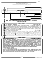
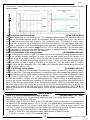
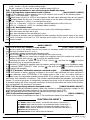
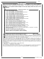
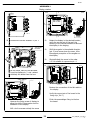
1
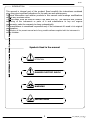
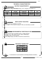
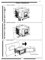
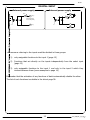
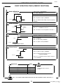
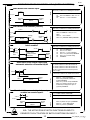
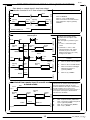
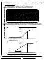
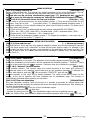
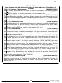
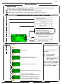
OPERATING AND INSTALLATION MANUAL
CONVERTER
SE 56
SE 56
INDEX
q
Introduction ________________________________________________________________________________pag.3
§
Symbol Used on the manual________________________________________________________________pag.3
q
Technical characteristics _____________________________________________________________________pag.4
§
Electrical characteristics ___________________________________________________________________pag.4
§
Environmental conditions of use ____________________________________________________________pag.4
§
Operative temperature ____________________________________________________________________pag.4
§
Overall dimensions _______________________________________________________________________pag.5
Electrical connections ________________________________________________________________________pag.6
§
Grounding instructions ____________________________________________________________________pag.6
§
Power supply converter ___________________________________________________________________pag.6
§
Terminal block M1 for compact, separate and panel version ______________________________________pag.7
§
Electrical connections sensor-converter _______________________________________________________pag.8
q
Inputs/outputs ______________________________________________________________________________pag.9
§
Expansion modules (no rele module)________________________________________________________ pag.10
§
Expansion modules (rele module) __________________________________________________________ pag.11
§
Digital Input ___________________________________________________________________________ pag.12
§
On/Off output wiring (up to 1250 Hz) - low frequency __________________________________________ pag.15
§
On/Off output wiring (up to 12500 Hz) - high frequency ________________________________________ pag.15
§
Analogical output - 0\4÷20 mA____________________________________________________________ pag.15
q
Start up and maintenance of the instruments _________________________________________________ pag.16
q
How to access at the instrument functions ____________________________________________________
§
Converter visualization pages _____________________________________________________________
§
Converter visualization pages with currency enable ____________________________________________
§
Flags interpretation and led _______________________________________________________________
§
Converter key board _____________________________________________________________________
§
Converters menues _____________________________________________________________________
§
Functions description ____________________________________________________________________
§
Access codes ___________________________________________________________________________
§
Block levels ____________________________________________________________________________
§
Access the configuration menu_____________________________________________________________
q
Programming functions _____________________________________________________________________ pag.27
q
Batch ______________________________________________________________________________________
§
Enable batch ___________________________________________________________________________
§
Programming batch______________________________________________________________________
§
Start / stop batch _______________________________________________________________________
§
Important notes ________________________________________________________________________
q
Alarm messages ___________________________________________________________________________ pag.37
§
Causes and actions to be taken ____________________________________________________________ pag.37
§
Anomalies codes _______________________________________________________________________ pag.37
pag.17
pag.17
pag.17
pag.18
pag.19
pag.20
pag.21
pag.24
pag.26
pag.26
pag.35
pag.35
pag.35
pag.36
pag.36
APPENDIX 1
q
Display rotation ______________________________________________________________________________ pag.38
2
210_EN_BU_4_3_5X.d
oc
SE 56
INTRODUCTION
This manual is integral part of the product. Read carefully the instructions contained
since they give important indications for the safe use and maintenance.
Technical information and relative products in this manual could undergo modifications
without any previous notice.
The flow meter must be used for what it has been built for. The improper use, possible
tampering of the instrument or parts of it and substitutions of any not original
components, make the warranty to decay automatically.
The manufacturer is considered responsible only if the instrument it’s used in his original
configuration.
Reproduction of the present manual and of any possible software supplied with the instrument is
strictly forbidden.
Symbols Used in the manual
ATTENTION
DANGER ELECTRIC SHOCK
WARNING
PRECAUTIONS
3
210_EN_BU_4_3_5X.d
oc
SE 56
TECHNICAL CHARACTERISTICS
ELECTRIC CHARACTERISTICS
Classification of the instrument: class I, IP 67, category of installation II
Power supply
versions
HV
LV
LLV
Power supply
voltage
90÷265 Vac
18÷45 Vac/dc
10÷35 Vdc
Power supply
frequency
44÷66 Hz
0-44÷66 Hz
Pmax
20W/25VA
20W/25VA
20 W
current
max
0,25 A
1,6 A
1,5 A
INPUT/OUTPUT ISOLATION
q
Input/output are insulated up to 500V
The output 4÷20 mA and the output 24 Vdc are electrically connected
ENVIRONMENTAL CONDITIONS OF USE
q
The instrument can be installed inside or outside buildings
Altitude: from –200 a 6000 m (from -656 to 19685 feet)
Humidity range: 0÷100% (IP 67)
Line voltage range: (see table on technical characteristics)
OPERATING TEMPERATURE
CONVERTER
Ambient Temp.
Min.
Max
°C
°F °C °F
-20* -4* 60 140
* For discontinuous use, the installation of a heating resistance is necessary
4
210_EN_BU_4_3_5X.d
oc
SE 56
OVERALL DIEMENSIONS
COMPACT VERSION
146
138
146
170
138
SEPARATE VERSION
146
230
146
138
170
25
138
PANEL VERSION
0
137.
160.0
72.0
80.0
67.0
145.
0
.0
144
5
IP65 (OPTIONAL)
210_EN_BU_4_3_5X.d
oc
SE 56
GROUNDING INSTRUCTIONS
For the correct operation of the meter it’s NECESSARY that sensor and liquid are
equipotential, so ALWAYS connect sensor and converter to the ground
CONVERTER POWER SUPPLY
q
Wall version
q
M3
L
(+)
q
N
(-)
q
Panel version
q
M3
L
(+)
N
(-)
Before connecting the power supply, verify that
the mains voltage falls between the limits
indicated on the tag plate
ATTENTION: the converters on dc power
supply line are not protected against the
inversions of polarity.
For the wiring use only approved conductors,
with fireproof properties.
The power supply line must be equipped with
an external protection for current overload (fuse
or automatic line breaker with limiting capacity
not greater than 10 A).
In the proximity of the instrument Provide a
circuit breaker that must be easily accessible
from the operator and clearly identified.
NOTE: characteristics of meter’s power supply, see
page 4
6
210_EN_BU_4_3_5X.d
oc
SE 56
ELECTRICAL CONNECTIONS
TERMINAL BLOCK M1 FOR COMPACT/SEPARATE VERSIONS
Power supply
IF2 socket
LOCK
1
Signalling LED with light:
interpretation at page 18
2 3 4 5 6 7 8 9 10
11 12 13 14 15 16 17 18 19 20
21 22 23 24 25 26
M3
27 28 29 30 31 32
M1
M2
Dip switch for block levels enabling
Dangerous voltage on block 12-13:
- 60 Vdc Max
- 250 V Max on commutation coils
TERMINAL BLOCK M1 FOR PANEL VERSIONS
Power supply
M2
Dangerous voltage on blocks 12-13:
- 60 Vdc Max
- 250 V Max on commutation coils
26 25 24 23 22 21
32 31 30 29 28 27
M1
20 19 18 17 16 15 14 13 12 11
10 9 8 7 6 5 4 3 2 1
M3
IF2 socket
Dip switch for block levels enabling
7
210_EN_BU_4_3_5X.d
oc
SE 56
ELECTRICAL CONNECTIONS SENSOR TO CONVERTER
SEPARATE VERSION
TERMINAL BLOCK M1
1
2
E1
E2
3 C
4 SH
11 SH
12 B1
C015
C016
ELECTRODES
E1
E2
C
INPUT
SH
+
-
RS485
4-20mA
B
+
A
-
1 2 3 4 5 6 7 8 9 10
13 B2
11 12 13 14 15 16 17 18 19 20
SH
Sudden movements of the electrodes
cable, can cause noises on measure
B1
COILS
B2
SH
+
24V
C
E
OUT1
C
E
OUT2
24V
Max length of cable: m 20
PREAMPLIFER VERSION
Cavo 1
Cavo 2
Cavo 3
Cavo 12
Cavo 13
Cavo 6
Cavo 7
Cavo 8
Cavo 9
Cavo 10
10 9 8 7 6 5 4 3 2 1
From pin 1 to pin 5 cables
connected to the sensor
C014
From pin 6 to pin 10 cables
connected to the converter
10 (preamp.)
1
1 (E1)
9 (preamp.)
2
2 (E2)
8 (preamp.)
3
3 (C)
4
4 (SH)
11
11 (SH)
7 (preamp.)
12
12 (B1)
6 (preamp.)
13
13 (B2)
Max length of the cable C014 : 500 m
8
210_EN_BU_4_3_5X.d
oc
SE 56
INPUT/OUTPUT
LEGENDA
OPTIONAL MODULE (NO RELE MODULE)
q
ME200: 2 programmable on/off outputs
q
ME201: 1 programmable on/off output + 1
high frequency output
q
ME202: 1 0/4…20mA output
programmable on/off output
q
ME203: 1 RS232 port + 2 programmable
on/off outputs
q
ME204: 1 RS232 port + 2 programmable
on/off outputs + 1 0/4…20mA out
q
ME220: see the manual
+
SC: Cable shield, electrically connected to
ground and to the casing
CTS: Input terminal of the signal “CLEAR TO
SEND” of the RS232 port
2
RD: Input terminal of the signal “RECEIVE
DATA” RS232 port
TD: Output terminal of the signal “TRASMIT
DATA” of the RS 232 port
SG: Terminal “SIGNAL GROUND” common to
all signals of the RS232 port
C: Terminal connected with the COLLECTOR of
the transistor of the on/off output
OUT 3
RS 232
E
C CTS RD TD SG
21 22 23 24 25 26
20
(M1)
27 28 29 30 31 32
+
INP2
E
C
OUT 4
SC
+
4..20mA
9
210_EN_BU_4_3_5X.d
oc
SE 56
INPUT/OUTPUT
LEGENDA
OPTIONAL RELE’ MODULE
ME205: 2 relay outputs with 1 NO contact + 1
NC contact each, 2A 60Vac, 60W/125Va
q SC: Cable shield, electrically connected to
ground and to the casing
ME207: 2 relay outputs with 1 NO contact + 1
NC contact each, 2A 250Vac, 60W/125Va
q C: relay – common
q NC: Normally closed contact
q NO: Normally open contact
OUT 3
OUT 4
C
14
(M1)
NC
NO
C
NC
NO
OUT 4
OUT 3
NO
NC
C
NO
NC
C
26 25 24 23 22 21
21 22 23 24 25 26
32 31 30 29 28 27
SC
10
210_EN_BU_4_3_5X.d
oc
SE 56
DIGITAL INPUT
External power supply
Internal power supply
+24
10 K
5 (+)
15
5
10 K
3/40 Vdc (ON)
0/1,5 Vdc (OFF)
6
6 (-)
0
20
The functions referring to the inputs could be divided in three groups:
1)
only assignable functions to the input 1 (page 12)
2)
Functions that act directly on the inputs independently from the select input
(page 13)
3)
only assignable functions to the input 1 and only to the input 2 which they
interact between them (some examples to page 14)
Remember that the activation of any functions of batch automatically disable the other.
The list of such functions is suitable in the tab at page 36.
11
210_EN_BU_4_3_5X.d
oc
SE 56
OPERATION ON INPUT ON/OFF
INPUT OPERATION STAGE (GENERIC FUNCTIONS)
Auto-calibration
Tmin<T<1sec. = autocalibration
T > 1 sec. = Auto zero
AUTOCALIB. OFF
Necessary conditions for enabling the function
3-40 V
POS. 5.7 ENABLED
POS. 5.9 (batch on input 1) DISABLED
0-1,5 V
POS. 5.10 batch functions assign to input 2 (optional)
DISABLED
T
Reset totalizes
Necessary conditions for enabling the function
BLOCK
RESET
3-40 V
POS. 5.1 ÷ 5.4 ENABLED at least one
N.B.: This function is even assignable to the input 2
0-1,5 V
Tmin = 100ms
T
Block totalizes
Necessary conditions for enabling the function
Block totalizes
POS. 5.6 ENABLED
3-40 V
POS. 12.5 (auto-batch) DISABLED
POS. 12.7 (batch consent) DISABLED
0-1,5 V
Totalizers active
Range change
Necessary conditions for enabling the function
Scale 2
POS. 5.8 ENABLE
3-40 V
POS. 5.9 (batch on input 1) DISABLED
POS. 5.10 batch functions assign to input 2
(optional) DISABLED
0-1,5 V
Scale 1
Speed rate
10 Hz
20 Hz
50 Hz
80 Hz
150 Hz
POS. 6.1-6.4 end-batch functions assign to output 2
1 e/o 2 DISABLED
Tmin
220 ms
110 ms
45 ms
30 ms
15 ms
ATTENTION: time T must be
to Tmin
≥
N.B.: THE FUNCTIONS ABOVE INDICATED ARE ENABLED ONLY ON INPUT 1
12
210_EN_BU_4_3_5X.d
oc
OPERATION STAGE ON INPUT 1 OR 2 (BATCH FUNCTION)
Start batch from remote input
Necessary conditions for enabling the function
INPUT
3-40 V
0-1,5 V
Closing
valve
BATCH
Start batch from consent (remote)
Necessary conditions for enabling the function
INPUT
3-40 V
0-1,5 V
Closing
valve
Opening
valve
OUTPUT
Opening
valve
BATCH
Start batch from remote input with autobatch enabled
<5 Sec.
0-1,5 V
Closing valve
quantity to batch
memorized
AUTO-BATCH
Closing
valve
OUTPUT
Opening
valve
BATCH
Start batch from remote input with
automatic selection of formula 00/03
0-1,5 V
INPUT
Start
T
3-40 V
Formula selection
BATCH
Closing
valve
OUTPUT
Opening
valve
INPUT
Start batch from remote input 1 reset p+
enabled on remote input 1
T
3-40 V
Start
POS. 5.9 ENABLED or POS. 5.10 on
batch
POS. 6.1 ÷ 6.4 on batch
POS. 12.7 (CONSENT MODE) ENABLED
Necessary conditions for enabling the function
INPUT
3-40 V 5 Sec.
q
POS. 5.9 ENABLE or POS. 5.10 on
batch
q
POS. 6.1 ÷ 6.4 on end batch
OUTPUT
Opening
valve
SE 56
q
q
q
q
q
q
POS. 5.9 ENABLED or
POS. 5.10 on batch
POS. 6.1 ÷ 6.4 on end batch
POS. 12.5 (auto-batch) ENABLED
POS. 12.7 (consent mode)
DISABLED
T= 100ms ±50ms for select the formula 00
T= 200ms ±50ms for select the formula 01
T= 300ms ±50ms for select the formula 02
T= 400ms ±50ms for select the formula 03
In case of stop batch from remote input the
time of input
pulse must be > 50ms
Necessary conditions for enable the function
POS. 5.9 ENABLE or POS. 5.10 on batch
POS. 6.1 ÷ 6.4 on end batch
POS. 12.6 (automatic selection of
formula) ENABLED
POS. 12.7 (consent mode) DISABLED
POS. 5.10 selection function for the
formula 00/01 assigned to input 2
(optional) DISABLED
T BEETWEEN 1 E 4 = RESET TOTALIZER
T<1 = START E RESET TOTALIZER
Necessary conditions for enabling the function
Opening
valve
Closing
valve
BATCH
OUTPUT
0-1,5 V
POS. 5.9 (batch on input 1) ENABLED
POS. 6.1 ÷ 6.4 on AND BATCH
POS. 5.2 (reset P+) ENABLED
N.B.: THE ACTIVATION OF BATCH FUNCTIONS ON INPUT 2
PREVENTS THE ACTIVATION OF BATCH FUNCTIONS ON INPUT 1
13
210_EN_BU_4_3_5X.d
oc
OPERATION STAGE ON INPUT 1 AND 2 (BATCH FUNCTION)
Start batch on remote input 1 stop from output
selection formula 00 o 01 from remote input 2
BATCH FORMULA 00
BATCH FORMULA 01
3-40 V
BATCH FORMULA 00
Closing
valve
Opening
valve
BATCH FORMULA 01
POS. 5.9 ENABLED
POS. 6.1 or 6.4 on AND BATCH
POS. 5.10 function of formula selection
00/01 assigned to input 2 (optional)
ENABLED
OUTPUT
Closing
valve
INPUT 2
0-1,5 V
Opening
valve
Necessary conditions for enabling the function
INPUT 1
Start
3-40 V
Block totalizer from remote input 1 start batch from
remote input 2
T
INTERRUPTED BATCH
RESTART INTERRUPTED
BATCH
T
3-40 V
Closing
valve
Opening
valve
T
T<1 Sec.
RESET
Start
Start
0-1,5 V
INTERRUPTED BATCH
OUTPUT
NEW BATCH
3-40 V
0-1,5 V
3-40 V
0-1,5 V
Closing
valve
Closing
valve
NEW BATCH
3-40 V
2) T between 1 e 4 Sec = reset
interrupted batch. N.B.: will be
necessary to give a new start
impulse to the input 2 (T< 1Sec)
to begin a new batch
Necessary conditions for enabling the
function
q
POS. 5.6 (Block totalize) ENABLE
q
POS. 6.1 OR 6.4 on END BATCH
q
POS. 5.10 funzione di dosaggio
attribuita ad ingresso 2
(optional) ENABLE
q
POS. 5.2 (P+) ENABLE
The block of the totalizer always determines
the stop of batching. With the T2 reset
function enabled on the input 1 descent front,
the batch totalizer in use goes to zero.
Therefore both the presence of the consent or
a new pulse on the input 2 will determine
The start of a new batch
Necessary conditions for enabling the function
q
q
RESET T2
INPUT 1
INTERRUPTED BATCH
BLOCK
Opening
valve
OUTPUT
INPUT 2
Block and reset totalize from remote input 1
start batch from remote input 2 consent mode
to batch enable
Start
Opening
valve
The block of the totalizer always
determines the interruption of the
batch. Exciting
again the input 2 is possible to get 2
results:
1) T< 1Sec = restart interrupted
batch
INPUT 1
BLOCK
Closing
valve
Opening
valve
Closing
valve
Opening
valve
OUTPUT
Closing
valve
Opening
valve
T<1 Sec.
0-1,5 V
T comprise tar 1 e 4 Sec.
INPUT 2
Start
INPUT 2
Start
3-40 V
SE 56
0-1,5 V
14
q
q
POS. 5.6 (Block totalizer) ABILITATO
POS. 5.10 function of batch assigned to
input 2 (optional) ENABLE
POS. 12.7 (consent mode) ENABLE
POS. 5.2 (P+) ENABLE
210_EN_BU_4_3_5X.d
oc
SE 56
OUTPUTS WIRING
Output on/off 1250 Hz
16 (out1)
18 (out2)
43V
17 (out1)
19 (out2)
Opto-insulated output with collector and
emitter terminals floating and freely
connectable
Maximum switching voltage: 40 Vdc
Maximum switching current: 100mA
Maximum saturation voltage between
collector and emitter @100mA: 1,2V
Maximum switching frequency (load on
the collector or emitter, RL=470Ω,
VOUT=24Vdc): 1250Hz
Maximum reverse current bearable on the
OUT 1/OUT 2 standard - OUT 3/OUT 4 with modules (page 9)
Output on/off 12500 Hz
q
30
q
q
q
43V
q
q
29
q
q
Opto-insualted output with collector and emitter terminals
floating and freely connectable. In order to get the maximum
speed performances it is necessary to connect the emitter to
the common terminal of the outputs (0V), while the load has
to be on the collector. This output is internally connected to
the power supply source 24 Vdc available on the terminal
block.
Maximum switching voltage: 40Vdc
Maximum switching current: 100mA
Maximum saturation voltage between collector and emitter
100mA, load on the collector and internal power supply: 0,3V
Maximum saturation voltage between collector and emitter
100mA, load on the emitter and internal power supply: 3V
Maximum switching frequency, load on the collector and
internal power supply: (RL=470Ω, VOUT=24Vdc): 12500Hz
Maximum switching frequency, load on the emitter or
external power supply: (RL=470Ω, VOUT=24Vdc): 2500Hz
Insulation from the other secondary circuits (except 24V and
4…20mA outputs): 500 Vdc
Only with ME 201 module
Output 0-4÷20mA
+24V INTERNAL
mA
9 (+)
I
0/4..20mA OUT
q
q
q
q
q
Opto-insulated output
Maximum load 1000 ohm
Maximum voltage without load 27 Vdc
Refresh frequency equal to the sample frequency
of the connected sensor
protected against persistent over voltages till 30
Vdc
10 (-)
24V COMMON
The converter detect a loss of load on the 4÷20mA output; to disable this
function set the value "mA Val. Fault" to 0 ( pag 28 Pos. 4.7)
15
210_EN_BU_4_3_5X.d
oc
SE 56
START UP AND MAINTENANCE OF THE INSTRUMENTS
Before starting up the instrument please verify the following:
Power supply voltage must correspond to that specified in the name plate
Electric connections must be done as described at page 8
Ground connections must be done
Verify periodically:
q
q
q
q
q
The integrity of the power supply cables, wiring and other electrical parts
connected
The integrity of the instrument’s housing (this must not have bruises or other
damages that may compromises the hermetical sealing)
The tightening of the sealing elements (cable glands, covers, etc.)
The integrity of the front panel (display and keyboard), damages may
compromise the sealing
The mechanical fixing of the instrument on the pipe or on the wall stand
16
210_EN_BU_4_3_5X.d
oc
SE 56
VISUALIZATION PAGES
The direct exposure of the converter to the solar rays, could damage
the liquid crystals display. N.B. Contrast set see page 32 pos. 8.3
Flow rate value
Analogical bar of flow rate variations
% full scale
Flow direction +/reg.regolazione
See: anomalies codes and
interpretation of flags
Date/time or alarm
*
Direct / reverse totalizer
C=Calibration
S=Simulation
Sampling rate
Flow speed
Push to change visualisation
Scale (1=low); (2=high)
Flow rate value
Time scale (vedi Pos. 3.1)
% full scale
% full scale
Measure units
Active scale
Flow direction
* The maximum digit shown from the totalizer is 999999999 independently from the number of
selected decimal. Beyond this value the totalise are reset.
CONVERTER VISUALIZATION PAGE WITH CURRENCY FUNCTION ENABLE
Flow rate value
Total direct totalizer
Partial reverse totalizer
Currency value
NOTE
The visualization of the pages can be change respect to some functions enabled o disabled
(Pos. 8.4 - 8.8 – 8.10 and batch functions)
17
210_EN_BU_4_3_5X.d
oc
SE 56
Flags interpretation and LED
FLAGS
INTERPRETATION FLAGS
DESCRIPTION
Alarm max activated
Alarm min activated
- Interruption coils circuit
!
- Segnal error
- Empty pipe
C
Calibration running
S
Simulation
Pulse output saturation (
reduce TIME PULSE )
FLAG
M
m
LED
LOCK
1 2 3 4 5 6 7 8 9 10
M3
11 12 13 14 15 16 17 18 19 20
M1
LED INTERPRETATION
PERMANENT LIGHT: initialisation
FLASHING LIGHT ( 1 sec.): normal function
FLASHING LIGHT (<1 SEC.): alarm on
The LED signals the real alarm status only if the display visualizes one of
the visualization pages suitable to page 17
ATTENTION: in the panel version the LED is not visible
18
210_EN_BU_4_3_5X.d
oc
SE 56
KEYBOARD
SHORT PRESSING (< 1 SECOND):
It increases the numeric figure or the parameter selected by the cursor
It goes to the previous subject on the menu
batch start/stop (when enabled)
LONG PRESSING (> 1 SECOND):
It decreases the numeric figure or the parameter selected by the cursor
It goes to the next subject on the menu
SHORT PRESSING (< 1 SECOND):
It moves the cursor rightward on the input field
It goes to the following subject of the menu
It changes the display of the process data
LONG PRESSING (> 1 SECOND):
It moves the cursor leftward on the input field
It goes to the previous subject on the menu
SHORT PRESSING (< 1 SECOND):
It enters /leaves the selected function
It enables the main menu for the instrument configuration
It cancels the selected function under progress
LONG PRESSING (> 1 SECOND):
It leaves the current menu
It enables the totalise reset request (when enabled)
It confirms the selected function
BLIND VERSION
For converter without keyboard (blind version), the
programming of functions is made up by the IF2
serial device:
19
210_EN_BU_4_3_5X.d
oc
SE 56
MENU DEL CONVERTITORE ML210
Some of more use functions are available in immediate way in the “Quick start menu”
pressing the key
. This menu can be disabling by the function 8.6 in the display
menu; in this case, pressing the key
the access will be directly to the main menu.
QUICK START MENU FUNCTIONS
Description function from page 20
Automatic optimization of the parameters (see below)
Access to all functions
The functions “batching setup, regulation setup, flow measure setup” they
instantaneously shape the instrument for the set up operation modifying in optimal way
all the parameters refer to the chosen operation. For enable one of three types of
operation press on the function the key
and then the key
20
to confirm.
210_EN_BU_4_3_5X.d
oc
SE 56
ML210 Functions
(for detail functions with symbol “*”see the manual from page 27)
Attention: The function in grey colour are visualized on display only with other active
functions or with optional modules
1.1
1.2
1.3
1.4
1.5
Insert ND of sensor ( 0-3000 )
Calibration data of sensor visualized on sensor’s label
Sensors model: Enter the first two characters of the serial number of the sensor
Position for insertion sensors: 0=1/8DN, 1=1/2DN, 2=7/8DN
Factory parameter
1.6
1.7
1.8*
1.9*
length of the cable connecting the sensor to the converter
Enables the empty pipe detection feature
Enables the automatic zero calibration system
Enables the automatic calibration procedure of the empty pipe detection
2.1*Full scale value set for range N.1
2.2*Full scale value set for range N.2
2.3* Unit of measure and number of decimal totalizes
2.4* Pulse value on channel 1
2.5* Pulse value on channel 2
2.6* Duration of the pulse generated on channel 1
2.7* Duration of the pulse generated on channel 2
2.8 Full scale freq. for channel 1 (0.1Hz-1000.0Hz) (0.1Hz-10000Hz con modulo opt.)
2.9 Full scale freq. for channel 2 (0.1Hz-1000.0Hz) (0.1Hz-10000Hz con modulo opt.)
2.10Enable/disable the selection of mass units on full scale set
2.11Specific gravity set in kg/dm³
3.1* Time constant
3.2 Filter on the power supply: 0.1s=“ready” measure; 0.5s=filter of noise on the liquid
3.3* Acceleration threshold
3.4* Anomalous signal pick cut off threshold
3.5 Low flow zero threshold: 0-25% of full scale value
3.6 Enable every hour a internal cycle of calibration. The measure it's stopped for 8-15 sec.
3.7* Automatic change of scale
3.8* Energy saving
4.1 Maximum value alarm set for direct flow rate
4.2 Maximum value alarm set for reverse flow rate
4.3 Minimum value alarm set for direct flow rate
4.4 Minimum value alarm set for reverse flow rate
4.5 Hysteresis threshold set for the minimum and maximum flow rate alarms
4.6 Empty pipe detection threshold. It’s automatically set by the function 1.9
4.7*Current output value in case of failure
4.8*Frequency output value in case of failure
4.9*Batch safety timer
21
210_EN_BU_4_3_5X.d
oc
SE 56
5.1* Total direct (positive) flow totalise reset enable
5.2* Partial direct (positive) flow totalise reset enable
5.3* Total reverse (negative) flow totalise reset enable
5.4* Partial reverse (negative) flow totalise reset enable
5.5 Reset totalise of pulse from digital input (see page 12)
5.6 Totalise counting lock command (see page 12)
5.7* Autozero calibration external command
5.8 Range change external command (see function 3.7)
5.9 Batch start/stop external command (see batch functions)
5.10* Functions assigned to input 2
6.1* Output 1 functions
6.2* Output 2 functions
6.3* Output 3 functions
6.4* Output 4 functions
6.5* Duty cycle value for pulses/frequency output
6.6* Choice of the function and the range of current output n.1
6.7* Choice of the function and the range of current output n.2
7.1
7.2
7.3
7.4
7.5
7.6
7.7
7.8
7.9
7.10
7.11
Choice of the communication protocol for the IF2 device
Choice of the communication protocol for the RS232 port
Address value of converter (range 0 – 255)
Speed of the RS485 output (possible choices: 2400, 9600, 19200, 38400 bps)
Speed of the RS232 output (possible choices: 2400, 9600, 19200, 38400 bps)
Print function enables (optional; see manual MI200)
Print of the performed batch
Stampa dei dati ad intervalli regolari ed impostabili
Print of the data process on regular intervals
Address of a further converter connected like a terminal
Start remote connection to the terminal. Connection interrupted after 10sec. of inactivity
8.1 Choice of the language: E= English, I=italian, F= French, S= Spanish
8.2 Updating frequency on the display: 1-2-5-10 Hz
8.3* Display contrast
8.4 Partial totalizer visualization (with batch enable the function is always on)
8.5 Date and time visualization with data logger enable
8.6 Quick start menu visualization
8.7 Enable the change value of the totalizers (see function 5.1-5.4)
8.8* Enable the page of net totalizer (difference between direct and reverse. see page 17)
8.9 Reset the processor of the display (useful in case of particular badly operations of the display)
8.10 Visualizes the values of the partial totalirer in the unit of selected currency
8.11 Choice of the numbers of decimals for the visualization currency value: From 0 to 3
8.12*Value of conversion/currency for direct totalizer
8.13*Value of conversion/currency for reverse totalizer
22
210_EN_BU_4_3_5X.d
oc
SE 56
9.1*
9.2
9.3
9.4
9.5
9.6
9.7
9.8
9.9
Date and time set
Automatic data logger enable
Interval time for the data logging function: 1, 2, 3, 6, 8, 12, 24, 48 hours
Displaying of the data stored in the data logger
Displaying of the last 64 alarms stored in the data logger
Visualization function of minimum and maximum peak of flow rate
Logged data cancel function
Reset all alarm events
Reset all minimum and maximum peak of flow rate stored
10.1* Enable the calibration of the converter
10.2* Converter autotest
10.3* Flow rate simulation enabling
11.1 Level 2 access code enter
11.2 Block level function can be set from 0 to 3
11.3 Load factory data pre-set
11.4 Load user data saved
11.5 Save user data
11.6 Visualisation of the total operation hours of the converter (function not editable)
11.7 Ignore the calibration error during the switch on test
11.8 Ks Coefficient
Menu 12: Menu visualized only with batch active
(see from pag. 35)
12.1 of batch cycles to be done to define the value of compensation. Value 0=OFF
12.2* % limit of compensation threshold
12.3* Compensation value
12.4* Prebatch value
12.5* Auto-batch
12.6* Automatic selection of batch formula
12.7* Static consent of batch
23
210_EN_BU_4_3_5X.d
oc
SE 56
ACCESS TO THE CONFIGURATION MENUES
The access to the configuration menu can take place in two different modes:
q
q
Through the “Quick start menu” where it is possible to access directly to
some of the principal functions
Through the “Main menu” where it is possible to access to all function with
access code ≤ 2
We show below some examples relating to the change of the value in the “Fs1”
function
EXAMPLE: modifying the full scale value from 4dm³/s to 5dm³/s.
from “Quick start menu”
Enter in the “Quick start menu”
Access to the function “Fs1”
Push
repeatedly
Change the value
Confirm the new value
Long push
Main page
24
210_EN_BU_4_3_5X.d
oc
SE 56
EXAMPLE: modifying the full scale value from 4dm³/s to 5dm³/s.
from “Main Menu” (quick start menu enable)
Enter in the “Quick start menu”
Access to the “Main Menu”
X 5 TIMES
Access to the “Scale” menu
Change the value
Access to the function “Fs1”
Push
repeatedly
Long push
Confirm the new value
Main page
Long push
25
210_EN_BU_4_3_5X.d
oc
SE 56
ACCESS CODES
Some functions in the converter are enabled by the
access codes. The information’s of this manual are
related to all the functions available with L2 level.
All the functions available through higher level are
protected and reserved to the service.
FACTORY PRE-SETTINGS
ACCESS CODES
The converter is delivered with access code L2:
Description of the L2 access code
(Menu “11 Internal data” pos. 11.1)
11111
q with code L2 = 00000 you disable the
request of code
NOTE: the availability of the functions is
related to the selected block
and with the "Quick start menu" enable. Press
the key
to access to the "Quick start menu"
from one of the visualization pages
q * with L2 customised (freely chosen by the
user) you can proceed programming all the
functions up to L2 security level, entering the
code itself whenever you need enter the Main
menu
*ATTENTION: take note very carefully of the
customised code you have chosen, since there is
no way for the user to retrieve it if it forgotten
BLOCK LEVELS
the block level enables or disables the access to
the functions of the converter.
The available levels of block are the following:
(Menu “11 Internal data” pos. 11.2)
q
Level 0: it completely disables the access to
the functions. You can perform the following
functions through the keyboard:
§ Changing the display mode
§ Dosing Start/stop
§ Data printing
q
Level 1: it enables the access to the
following functions:
•
Totalise re-setting
•
Dosing functions modifications
q
Level 2: it enables the access to the
following functions:
§ Quick start menu
§ Scale (full enabling)
§ Display (partial enabling)
§ Diagnostics (partial enabling)
q
Level 3: it enables the access to all the
functions of level 2
26
The “Quick start menu” it’s enable by 8.6 function
(display menu); from the “Quick start menu” the
functions may be set without entering any access
code (see example 1 on page 24).
The last function allows to access the main menu.
FACTORY PRE-SETTINGS
BLOCK LEVELS
The converter is delivered with the following
block level:
3
If for several reasons you need to change the
block level, follow the steps:
q Set the dip switch on OFF position
q Access to the function “Block level” of menu
11 (main menu)
q Choose the desired level of block
To enable the selected block level place the DIP
switch on the ON position
When the Dip-switches are on “OFF”, all
functions are available.
LOCK
(OFF)
(ON)
Dip
switch
210_EN_BU_4_3_5X.d
oc
SE 56
FUNCTIONS DESCRIPTION
(description of the functions with access code< 3)
Identification of the function (not visualized on display)
MENU 1.SENSOR
(POS. 1) Nominal diameter of sensor
[ND=
XXXX]
Converter request
Menu visualized on the converter ( from 1 to 11)
Synthetic description of the function
N.B.: follow are detailed description only some functions of the converter
(see note to page 20)
MENU 1.SENSOR
(POS. 1.8) “Autozero” calibration
[AUTOZERO CAL.]
Enables the automatic zero calibration system. To perform the sensor it is absolutely necessary the
sensor is full of liquid and that the liquid is perfectly staying still. Even very small movement of the
liquid may affect the result of this function. When the percentage flow rate value is stable press the
key
. Check the percentage flow rate value goes to zero, otherwise repeat the operation again.
When the value is stable at zero, then press
.
(POS. 1.7) “Empty pipe” calibration
[E.P. CALIBR.]
This function enables the automatic calibration procedure of the empty pipe detection function.
Before performing this function, the sensor has to be completely filled with the liquid. The sensor has
then to be emptied again and then you should press the key
: the operation will have to be
confirmed by pressing the key
or any other key annul the operation. By this function the system
sets the value of a parameter, which could also be manually changed (see function “E.P.thr” menu 4ALARMS).
MENU 2.SCALES
(POS. 2.1-2.2) Full scale n° 1-2
[FS1-2=dm³/S X.XXXX]
Full scale value set for range N.1-2. There are four fields to fill in order to set this parameter, from
left to right: 1) volume unit of measure, 2) type of unit, 3) time unit of measure and 4) numeric
value. The selection is made by positioning the cursor on the field to modify. To change the type of
unit of measure (metric, British or American, mass or volume) the cursor has to be positioned on the
symbol “/” (field N. 2). When the nominal diameter is set to zero it is possible to modify only the
numeric field, since the unit of measure stays at m/sec. The following tables show the units of
measure available and the conversion factor by comparison with 1 dm3 and 1 kg. The converter
accepts any kind of combination of units of measure satisfying both the following conditions:
Numeric field value ≤ 99999
1
/25 fsmax ≤ numeric field value ≤ fsmax.
Where fsmax is the maximum full scale value corresponding to the sensor, equal to a 10 m/sec liquid
speed. The units of measure are shown as appear on the display. The British and American units are
diversified by using capital and small characters. Available units of mass and volume:
27
210_EN_BU_4_3_5X.d
oc
SE 56
cm3
ml
l
dm3
dal
hl
m3
Cubic centimetre
Millilitre
Liter
Cubic decimeter
Decalitre
Hectolitre
Cubic metre
in3
Gal
GAL
ft3
Bbl
BBL
yd3
kgl
KGL
Cubic inch
American gallon
British gallon
Cubic foot
Standard barrel
Oil barrel
Cubic yard
KAmerican gallon
KBritish gallon
G
Kg
T
Oz
Lb
Ton
Gram
Kilogram
Ton
Ounce
Pound
short tons
When a mass unit of measure is set, the specific gravity function is automatically enabled by the
system. The units of measure of time may be chosen among the values:
s=second,m=minute,h=hour,d= day.
(POS. 2.3) Unit of measure and number of decimal totalizes
[UM.tot:dm³X.XXX]
Setting the unit of measure and number of decimals for visualized the totalizes or the volumes to
batch. For set the unit of measure, position the cursor on field of the actual unit of measure; For set
the type of unit, position the cursor on the blank space between the unit of measure and the numeric
value; For set the number of decimal totalizes position the cursor on numeric field and choose one of
the possible combinations: 1000-01.00-001.0-00001.
*(POS.2.4-2.5) Pulse value channel 1 and unit of measure of tot. [IMP1-2=dm³X.XXXXX]
Setting of the pulse volume corresponding to channel 1-2 and of the totalizers measure units. There
are three fields to fill in to set this parameter, from left to right: 1) measure unit, 2) unit type and 3)
numeric value. The selection is performed by positioning the cursor on the field to be modified. To
change the unit type (metric, British or American, mass or volume) just position the cursor on the
blank space between the measure unit and the numeric value. When the nominal diameter is set to
zero it is possible to modify only the numeric field since the measure unit stays at meter (m) or feet
(ft). The possible measure units are those above described
(POS.2.6-2-7) Pulse duration channel 1-2
[TPUL1-2=msXXXX.XX]
Setting of the duration of the pulse generated on channel 1-2. Its value is expressed in milliseconds
and has to be between 0.4 and 9999.99. When the high frequency output is present, then the
minimum value can go down to 0.04 milliseconds.
ATTENTION: since the instrument cannot detect which type of device it is connected to, it is up to
the user to verify the set pulse duration is compatible with the external device processing such pulses.
If, for example, an electro-mechanical pulse counter is connected, then two kind of problems may
occur: if the pulse is too long than the coil may burn or, if it is too short, the counter may not be able
to count and eventually even cause the damaging of the output itself.
MENU 3.MEASURE
(POS. 3.1) Time constant
[TCONST=s XXXX.X]
This parameter affects the integrating filter making the instrument response quicker or slower,
according to the set value. A higher value corresponds to a more stable but slower measure, a
smaller value the opposite. The most common values are from 1 to 5 seconds. The valid range of
value it’s from 0 (integral filter disabled) to 6000.0 seconds. The following diagram shows the
response of the instrument for a flow rate variation from 0 to 100% within the T time constant period
(POS. 3.3) Acceleration threshold
Acceleration threshold set. The acceleration threshold stands for the limit beyond which a flow rate
variation determines an immediate response at the output, without being filtered by the time
constant. This system allows the instrument to have an immediate response in case of big variations
of the flow rate, filtering (and delaying) the response to small variations. The result of that is a very
stable measure, ready to follow the process. The value is set as percentage of the full scale value
from 0 to 125%. If such a value is set to zero any flow rate variation bigger than 0.5% of the full
scale value will immediately affect the outputs. The following diagram shows the instrument response
in two cases: a flow rate variation from 0 to 10% completely absorbed by the time constant effect
and a variation form 10% to 100% exceeding the acceleration threshold and then immediately sent
28
210_EN_BU_4_3_5X.d
oc
SE 56
to the output. In actual fact there is always a minimum time between the measure acquisition and the
outputs update.
(POS. 3.4) Peak cut off threshold
[PEAK THR=% XXX]
Anomalous signal pick cut off threshold set. This parameter allows setting the maximum value of
deviation of the actual measure sample by comparison with the average one. If the new value is
higher than the set limit, than such a value is “cut” to the limit value. This function is used to make
the meter less sensitive to big perturbations on the flow rate measure, as it may happen when there
are solids in suspension in the liquid hitting against the electrodes determining a high electrical noise.
The permitted values of this function range from 0 to 125 % and are referred to the full scale value.
If this parameter is set to zero the peak detection function is disabled and any new measure ample
will be accepted and processed as it is by the converter.
(POS. 3.7) Automatic scale change enable
[AUTORANGE=ON/OFF]
Enables the automatic change of scale. The meter may have two different working ranges in order to
suit to the variable process conditions. In order to get the best results out of this function it is
important range N.2 is bigger than N.1. When the flow rate increases and reaches the 100% of the
full scale 1, then the meter automatically switches to scale 2. When the flow rate decreases again
reaching a value on scale 2 equal to the 90% of full scale N.1, then the active scale is 1 again.
Allowed values for this parameter: ON / OFF. N.B.: the autorange doesn’t allow using the manual
change of range (see pos. 5.8)
(POS. 3.8) Energy saving enable
[E.SAVING=ON/OFF]
This function is used when the instrument is powered by a battery or solar cells, allowing an energy
saving up the 60-80. The energy consumption is controlled by the ratio between the measuring cycles
powering the coils and the cycles without powering the coils. When the flow rate is stable the number
of “off” cycles is higher than the “on” ones, so that the average consumption is strongly reduced. If
the flow rate suddenly changes, then the meter switches on a higher number of measuring cycles, in
order to get a higher response time, switching off the cycles as soon as the flow rate gets back to be
stable. If the flow rate varies below of the “acceleration threshold” (POS.18) percentage value, then
the meter goes on with “off” cycles, but as soon as the flow rate value exceeds such a threshold, the
meter switches on many measuring cycles again. Allowed values for this parameter: ON/OFF N.B.: to
optimise this function it is recommended choose a value for the acceleration threshold within 10÷15
(POS. 3.3)
MENU 4.ALARMS
(POS. 4.7) Current output value in case of failure
[mA VAL.FAULT =% XXX]
Setting of the value the 0/4...20 mA current output has to be in one of the following cases:
empty pipe; coils interrupted; ADC error
The allowed range is from 0 to 120% of the 0..20 mA scale, 120% corresponds to 24 mA and does
not depend on the selected range (0…20 / 4…20 mA). The NAMUR NE43 recommendation asks for a
alarms signalling value for the current output lower than 3.6 mA (<18%) or bigger than 21 mA
(>105%). It would then be preferable to set the value of this function at the 10%, so that the current
value in case of the a.m. cases would be 2 mA, allowing the following diagnostics:
current < 2 mA - 5%: line interrupted, power supply failure or faulty converter;
2 mA -5% ≤ current ≤ 2 mA + 5%: hardware alarm;
29
210_EN_BU_4_3_5X.d
oc
SE 56
4 mA ≤ current ≤ 20 mA: normal working range;
20 mA < current ≤ 22 mA: out of range, measure above 100% f.s.
N.B.: To set this parameter to zero corresponds to disable the alarm
(POS. 4.8) Frequency output value in case of failure
[Hz VAL.FAULT=%XXX]
Setting of the frequency value to assign to the on/off output in one or more of the following cases:
Empty pipe ; Coils interrupted ; ADC error
The allowed range is from 0 to 125% of the frequency full scale value. Although there are not specific
rules regulating cases like this one, it would be convenient to use the failure information as follows:
q 0% Hz ≤ frequency ≤ 100% f.s.: normal working range;
q 100% f.s. < frequency ≤ 110% f.s.: overflow, measure above the 100% of the f.s.;
q 115% f.s. ≤ frequency ≤ 125% f.s.: hardware alarm condition.
(POS. 4.9) Batch safety timer
This function is useful when you need control one or both of the followings condition:
q batch valve open and flow rate is zero
q batch valve closed and flow rate different to zero
When this alarm is activates, they are aborted the batch operation and the power supply of the valve.
The values of function are from 0 to 25.5 seconds and is active only if one or more of the batch
functions are enable.
MENU 5.INPUTS
(POS. 5.1-5.2-5.3-5.4) Totalise + reset enable
[T/P+/-RESET=ON/OFF]
To make the reset of the totalise from the key board it is necessary enable the function 8.7 (modify
tot.) and one of function from 5.1 to 5.4.
From visualisation pages, proceed in the following mode:
1) Push the key
, Set the L2 CODE if required and then push the key
2) Positioning the cursor on value field to modify the numerical value (it’s possible only modify the
totalizer enabled) push the key
to confirm the modified value
3) Positioning the cursor on “RESET TOTALIZ.?” Push the key
and then the key
to confirm
or any other key to cancel this operation.
With function 8.7 disabled it’s possible reset the totalizer pushing the key
from visualization page,
at the required “RESET TOTALIZ.?” Push the key
and then the key
to confirm or any other
key to cancel this operation
(POS.5.7)“Autozero” calibration external command enable
[CALIBRATION=ON/OFF]
When this function is active, applying a voltage on the on/off input terminals the meter performs a
autozero calibration cycle. ATTENTION: if the voltage pulse is less 1 sec., the meter performs a
calibration cycle for compensate possible thermal drifts. If the voltage pulse is more 1 sec, the meter
performs a zero calibration of measure. This function enables/disables the automatic zero calibration
system. To perform the sensor it is absolutely necessary the sensor is full of liquid and that the liquid
is perfectly staying still. Even very small movement of the liquid may affect the result of this function,
and, consequently, the accuracy of the system.
(POS. 5.8) Range change external command enable
[RANGE CHANGE=ON/OFF]
Range change external command enables. When this function is enabled, applying a voltage on the
on/off input terminals the meter switches to the second measuring range (Fs2).
N.B.: the autorange doesn’t allow using the manual change range (see pos. 3.7)
(POS.5.10)Functions assigned to input 2
[ING.2=XXXXXX]
Choice of the function to associate the input 2 The functions are listed in the table below.
FUNCTION FOR INPUT 2
OFF: DISABLE
T+ RESET: RESET TOTAL DIRECT TOTALIZER FOR DIRECT FLOW RATE (+)
P+ RESET: RESET PARTIAL DIRECT TOTALIZER FOR DIRECT FLOW RATE (+)
T- RESET: RESET TOTAL REVERSE TOTALIZER FOR REVERSE FLOW RATE (-)
P- RESET: RESET PARTIAL REVERSE TOTALIZER FOR REVERSE FLOW RATE (-)
BATCH: START/STOP BATCH
MD SELECTION: STATIC SELECTION OF FORMULA
30
210_EN_BU_4_3_5X.d
oc
SE 56
MENU 6.OUTPUT
(POS. 6.1-6.2-6.3-6.4) Function corresponding to on/off output 1-2-3-4 [OUT1=XXXXXX]
Choice of the function corresponding to digital Output 1. The functions are listed in the table to the
next page
The output 3-4 are optional and the output 4 it’ the only output, which can reach a 12.5
KHz frequency.
FUNCTION FOR OUTPUT 1, 2,3,4
OFF: DISABLED
#1 IMP+: PULSE ON CHANNEL 1 FOR POSITIVE FLOW RATE
#1 IMP-: PULSE ON CHANNEL 1 FOR NEGATIVE FLOW RATE
#1 IMP±: PULSE ON CHANNEL 1 FOR POSITIVE AND NEGATIVE FLOW RATE
#2 IMP+: PULSE ON CHANNEL 2 FOR POSITIVE FLOW RATE
#2 IMP-: PULSE ON CHANNEL 2 FOR NEGATIVE FLOW RATE
#2 IMP±: PULSE ON CHANNEL 2 FOR POSITIVE AND NEGATIVE FLOW RATE
#1 FREQ+: FREQUENCY CHANNEL 1 FOR POSITIVE FLOW RATE
#1 FREQ-: FREQUENCY CHANNEL 1 FOR NEGATIVE FLOW RATE
#1 FREQ±: FREQUENCY CHANNEL 1 FOR POSITIVE AND NEGATIVE FLOW RATE
#2 FREQ+: FREQUENCY CHANNEL 2 FOR POSITIVE FLOW RATE
#2 FREQ-: FREQUENCY CHANNEL 2 FOR NEGATIVE FLOW RATE
#2 FREQ±: FREQUENCY CHANNEL 2 FOR POSITIVE AND NEGATIVE FLOW RATE
SIGN: FLOW DIRECTION OUTPUT (ENERGISED = -)
RANGE: RANGE INDICATION OUTPUT (ENERGISED = SCALE 2)
MAX AL+: MAX DIRECT FLOW RATE OUTPUT(ENERGISED = AL. OFF)
MAX AL-: MAX REVERSE FLOW RATE OUTPUT(ENERGISED = AL. OFF)
MAX AL±: MAX DIRECT/REVERSE FLOW RATE OUTPUT(ENERGISED = AL. OFF)
MIN AL+: MIN DIRECT FLOW RATE OUTPUT(ENERGISED = AL. OFF)
MIN AL-: MIN REVERSE FLOW RATE OUTPUT(ENERGISED = AL. OFF)
MIN AL±: MIN DIRECT/REVERSE FLOW RATE OUTPUT(ENERGISED = AL. OFF)
MAX+MIN±: MAX AND MIN FLOW RATE ALARM OUTPUT (ENERGISED = AL. OFF)
EMPTY PIPE: EMPTY PIPE ALARM OUTPUT (ENERGISED = FULL PIPE)
OVERFLOW.: OUT OF RANGE ALARM OUTPUT (ENERGISED = FLOW RATE OK)
HW ALARM: CUMULATIVE ALARM OUTPUT interrupt coils, empty pipe, measure error (ENERGISED = NO ALARMS
BATCH AL: BATCH ALARM
EXT. COMM.: ONLY AVAILABLE WITH DATA LOGGER MODULE
BATCH SIN.: AT THE AND OF BATCH THE OUTPUT CHANGE STATUS
END BATCH.: END BATCH OUTPUT (ENERGISED =BATCH IN PROGRESS)
PREBATCH.: PREBATCH OUTPUT (ENERGISED = PREBATCH IN PROGRESS)
(POS. 6.5)duty cycle value for pulses/frequency output
[OUT.1=XXXXXX]
The duty cycle function define the time ratio between ON and OFF state when frequency output are
used: 50% it mean that the ON phase will be the same of OFF phase, 60% it mean that the phase
ON will be 60 % and phase OFF will be 40% of the total cycle time.
When pulses outputs are used , the duty cycle define the OFF phase because the ON phase it’s
already set with the function "PULSE DURATION"( see menu “SCALE” ) . In this case if is setting for
example the duty cycle at 50% and the pulse duration to 50ms, the OFF phase will be the same of
ON phase. The formula for calculate the minimum time of the OFF phase and the time of total cycle
is the following:
T. total cycle= 100 x (pulse duration in ms)/ (duty cycle)
T. OFF phase = T. total cycle - pulse duration
N.B.: If the value of the function is set to 0 the issue of the pulses happens in synchronous mode with
the flow rate therefore when is uses the function in frequency DOESN'T set the duty cycle to 0.
31
210_EN_BU_4_3_5X.d
oc
SE 56
(POS. 6.6-6.7) Function and the range of current output n.1-2
[OUT.mA1-2=X÷XX±]
Choice of the function and the range of current output N.1-2. The current output N.1 is optional and
it is mounted on the main board. There are three fields to modify for this function:
q Scale zero: 4 or 0 mA ; Full scale: 20 or 22 mA
q Field: + = positive, - = negative, ± = both, -0+ = central zero scale
The values corresponding to the scale points are shown in the following chart:
POSSIBLE FIELD
OutmA = 0 ÷ 20 +
OutmA = 0 ÷ 22 +
OutmA = 4 ÷ 20 +
* OutmA = 4 ÷ 22 +
OutmA = 0 ÷ 20 OutmA = 0 ÷ 22 OutmA = 4 ÷ 20 OutmA = 4 ÷ 22 OutmA = 0 ÷ 20 ±
OutmA = 0 ÷ 22 ±
OutmA = 4 ÷ 20 ±
OutmA = 4 ÷ 22 ±
OutmA = 0 ÷ 20 –0+
OutmA = 0 ÷ 22 –0+
** OutmA = 4 ÷ 20 –0+
OutmA = 4 ÷ 22 –0+
CURRENT VALUES IN mA ASSOCIATE TO THE % VALUE OF FULL SCALE
REVERSE FLOW VALUE
ZERO
DIRECT FLOW VALUE
≤ -110%
-100%
0%
+100%
≥+110%
0
0
0
20
20
0
0
0
20
22
4
4
4
20
20
4
4
4
20
22
20
20
0
0
0
22
20
0
0
0
20
20
4
4
4
22
20
4
4
4
20
20
0
20
20
22
20
0
20
22
20
20
4
20
20
22
20
4
20
22
0
0
10
20
20
0
1
11
21
22
4
4
12
20
20
4
4.8
12.8
20.8
22
In hardware alarm conditions “HW ALARM” (interrupted coils, empty pipe, measure error) the current
value is programmed by the function “mA VALL. FAULT” (pos. 4.7) and it is expressed as percentage
of a fixed current range, where: 0% = 0 mA e 110% = 22 mA.
* Example 1: out 4÷22 +
I (mA)
22 mA
20 mA
4 mA
-110% F.S.
-100% F.S.
** Example 2: out 4÷20 –0+
+100% F.S. +110% F.S.
zero
I (mA)
20 mA
12 mA
4 mA
-110% F.S.
-100% F.S.
+100% F.S. +110% F.S.
zero
32
210_EN_BU_4_3_5X.d
oc
SE 56
MENU 8.DISPLAY
(POS. 8.3) Display contrast set
[CONTRAST=X]
Display visual contrast set. The contrast can change according to the room temperature. The set
values are from 0 to 15. The entered value has effect only when leaving the function itself.
Contrast also can be set from visualization pages (pag. 17) pushing the key
for 8
second or more. In this way the contrast set that will be visualized at release of the key.
(POS. 8.12-8.13) Conversion factor for flow rate totaliser
[EUR/dm³+ =X]
Set the value of conversion/currency for direct totalise( positive ). There are three set fields for this
parameter, from left to right:
1) monetary token, 2 ) default/personalized monetary token, 3 )
conversion coefficient. For the selection setting the cursor over the field to modify. The mode set of
monetary token could be two:
1.
Choice of one of the 7 predetermined monetary tokens (standard ISO 4217-REV81):
EUR = Eur ; USD = USA ; dollar CAD = Canadian dollar ; AUD = Australian dollar ; GPB =
English pound ; CHF = Swissfranc ; JPY = Japanese yen.
2.
Choice three free characters (number or letter ) . To change the characters , the cursor has to
be positioned on the symbol “/” (field N. 2)
MENU 9.DATA LOGGER
(POS. 9.1) Date and time set
[· = dd/mm/yy hh:mm]
Date and time set. If the real time clock optional module is present, then the time setting is kept also
when the power supply is off, otherwise it is frozen till the power supply is back. For example, if the
power supply has been off for one hour, when switched on the instrument will be one hour late. The
calendar is valid till year 2091. N.B.: date and time are visualized on display only if the data logger is
enable (Pos 9.2).
MENU 10. DIAGNOSTIC
(POS. 10.1) Meter “calibration”
[CALIBRATION]
Enable the calibration of the meter. The activation of this function happens pressing the key
during the visualization of the function. Will be visualized the following question: " EXECUTE?" press
for more of two second the key
to proceed . Press any other key to delete the operation
(POS. 10.2) “Autotest” function enable
[SELF TEST]
Meter autotest function. This function stops the normal functions of the meter and performs a
complete test cycle on the measure input circuits and on the excitation generator. To activate this
function, after select it, push key
, at the question: “EXECUTE?” push the key
For start autotest, or any other key for delete operation. The result of the test is shown on the
display. At the end of operation will have visualized one of visualization page. This function is
automatically performed when switching on the device.
(POS. 10.3) Flow rate simulation
[SIMULATION]
Flow rate simulation enabling. With this function it is possible to generate an internal signal that
simulates the flow rate, allowing the outputs and all the connected instruments test. After enabling it,
the flow rate simulation can be:
- set: by pushing the key
from one of four visualization pages
- started: by pushing the key
after set it
- finished: by pushing the key
from visualization pages and then by pushing the key
.
N.B.: the enable of flow rate simulation disable the contrast regulation with the key
(Pos. 8.3)
33
210_EN_BU_4_3_5X.d
oc
SE 56
MENU 12.BATCH
Menu visualized only with batch active (output on batch and/or pos. 5.9 enable or 5.10
on batch)
(POS. 12.1) Number of batch samples
[N.SAMPLES=XXX]
Number of batch cycles to be done to define the value of compensation. This function allows to
automatically determine the average value for automatic compensation of system delay (POS. 9.3) .
Set to ZERO this function for manually introduction of the compensation value.
(POS. 12.2) % limit of compensation
[DIFF.THR=%XXX]
This value defines the percentage of maximum difference between the compensation value set (see
pos. 12.3) and the average compensation value defined with the function 12.1. Over this threshold
the new compensation value will be automatically set (if Number of batch samples is different from
zero)
(POS. 12.3) Compensation value
[V.COM.=XX.XXX]
This value, expressed in the same selected volume unit of measure, is the result of the difference
between the batch value set and the quantity of product really supplied due to the system delays:
closing valves, stop pumps, stop motors, etc. Attention: if you need to set manually the value of
compensation, preset to ZERO the Number of batch samples (POS. 12.1)
(POS. 12.4) Prebatch value
[V.PRE.=XX.XXX]
set the volume of liquid at which you want to enable the pre-batch. When the pre-batch volume “V
Pre” is reached the output (if enabled) is de-activated. This value is constant for all quantities to be
batched and must be set in current volume unit of measure. The pre-batch function is useful when
you need fast and accurate fillings.
(POS. 12.5) Enable/disable auto-batch function
[AUTO BATCH=ON/OFF]
Applying a voltage on the on/off input terminals for more than 5 second the valve controlled by the
meter stands open while the voltage is applied on the input. When the product has reached the
desired volume/level, removing the voltage from the input, the meter closes the valve and memorizes
the supplied product volume in the current memory batch (see "BATCH FUNTIONS"); the value
obtained with this procedure will be the volume supplied in every following batch. In order to modify
this value, repeat the operations above. This procedure set the safety timer at a value 1.25 times
greater than the time used to reach the batched quantity; after that the counter will be reset.
(POS. 12.6) Automatic selection of batch formula
[BM AUTO SEL=ON/OFF]
The function allows the automatic selection of the first 4 formulas depending on the duration of the
pulse of the batch start (see page 11 "Input operation stage"). This function is active only if the
function cons. mode (POS. 12.7) has not enabled. Besides, activating this function, the automatic
compensation of the batch volume is also excluded (the value of the parameter "N.medie" (POS.
12.1) will be automatically set to zero). However the manual compensation is possible introducing the
opportune value on the parameter "V.com" (POS. 12.3)
(POS. 12.7) Static consent of batch
[Cons. mode=ON/OFF]
The function enable the start and the stop of the dosing using a static signal, instead of an impulsive,
applied to the input (see pag. 11 "Digital input), this signal will have to stand applied all through the
batch. This function automatically disables the functions "BM AUTO SEL" (POS. 12.6) and " AUTO
BATCH" (POS. 12.5).
34
210_EN_BU_4_3_5X.d
oc
SE 56
BATCH FUNCTION.
ENABLE BATCH
Enable one of the following functions to enable and program the batch on the converter:
q POS. 5.9-5.10: START/STOP batch from input
q POS. 6.1-6.2: assign one of the functions to one of two output
Some examples of operation of such functions are visualized from page 11
VISUALIZATION PAGE WITH BATCH FUNCTION ENABLE
Programming formula n°
product Name
Batch in progress
Visualizations:
1) batch off: n° batch effected
2) batch on: decrease safety timer
3) programming: programming safety timer
indefinite if timer=0 timer disabled
Programming batch quantity
Visualization batched product
From the visualization pages
PROGRAMMING BATCH
For each formula you can
associate:
Input key code
Choose the formula number for associate
quantity batch (between 00 and 15)
Input quantity product for each batch
Product quantity
Product name
Maximum time for
batch (safety time for
each formula)
After activating the batch
function from visualization
page at pages 47, proceed
as in the aside example.
q
q
q
Input product name for batch (max 8 characters.)
Input maximum time for batch
If timer = 0, safety timer disabled max time set
= 6000 sec.
N.B. if to one output is assigned the function of
batch alarm, to the attainment of the maximum
time, beyond to the interruption of the batch,
will have activated also the alarm output
35
210_EN_BU_4_3_5X.d
oc
SE 56
START STOP BATCH
START: it is possible activate the start of batch in two different way:
from remote input: assigning the functions of start/stop batch to the input 1 (POS.
5.9) or input 2 (POS. 5.10) and using the input/s like visualized from page 12.
from keyboard: short pressing of the key
N.B.: the start of batch from keyboard is always on the descent front (release of the
key) and is not available with the function of batch consent (POS. 12.7)
1.
2.
STOP: the stop of batch can be due to three events:
1.
2.
keyboard or remote input (manual stop): short pressing of the key
end of batch: in this case the stop of batch will have activated from a output signal to
the attainment of the batch quantity
maximum time of batch: if a maximum batch time has been set and this is exceeded,
the batch in progress is stopped independently from the batched quantity
3.
Notes:
q during the batch the symbol of the active batch
visualized on video.
q
and the name of the formula are
When the batch outputs are enable, pushing for more of 5 sec. the key
, the outputs
will remain energized till the key is released. On the display, in place of the CT and ST
totalisers the following messages will appear:
!! VALVE !!
!! OPENED !!
IMPORTANT NOTES
The start of the batch disables any function listed below:
POS 5.10
POS 6.1÷6.4
BM AUTO SEL
BLOCK TOTALIZER
DISABLE
* DISABLE
POS 3.7-5.8
POS 3.8
POS 5.7
CALIBRATION
POS 5.10
DISABLE
POS 5.9
ENERGY SAVING
POS 5.9
AUTO BATCH
BM AUTO SEL
CONS. MODE
INPUT 1 ON START/STOP
BATCH
INPUT 2 ON START/STOP
BATCH
BM SELECT
OUTPUT ON END BATCH
AUTO BATCH
POS 12.5
POS 12.6
POS 12.7
POS 12.1
AUTO RANGE CHANGE OR
FROM INPUT
POS 5.6
INPUT 1 ON START/STOP
BATCH
POS 12.6
N. SAMPLES
POS 12.5
* SE UTILIZZATO INGRESSO 1
** VALORE A ZERO
DISABLE
DISABLE
DISABLE
DISABLE
DISABLE
DISABLE
*DISABLE
** DISABLE
DISABLE
DISABLE
** DISABLE
DISABLE
AGISCE SU
To optimize the performances of the meter used as a batch instrument, it is recommended to set it
as prompt as possible according to the plant requirements, choosing the opportune values of time
constant (pos. 3.1) and acceleration threshold (pos. 3.2).
36
210_EN_BU_4_3_5X.d
oc
SE 56
Alarm messages, causes and actions to be taken
Messages
ANOMALIES
ACTION TO TAKE
NO ALARMS
All works regularly
MAX ALARM
The flow rate is higher than the maximum threshold set
Check the maximum flow rate threshold set and the
process conditions
MIN ALARM
The flow rate is lower than the minimum threshold set
Check the minimum flow rate threshold set and the
process conditions
FLOW RATE >FS
The flow rate is higher than the full scale value set on the
instrument
Check the full scale value set on the instrument and
the process conditions
PULSE/FREQ>FS
The pulse generation output of the device is saturated and cannot
generate the sufficient number of impulses
Set a bigger unit of volume or, if the connected
counting device allows it, reduce the pulse duration
value
The measuring pipe is empty or the detection system has not
been properly calibrated
Check whether the pipe is empty or perform again
the empty pipe calibration procedure
EMPTY PIPE
-----
Batch interrupted for the followings condition:
BATCH ALARM
q Timer batch expired before the end of the batch
Verify:
q Batch valve open and flow rate to zero for a time longer q Presetting
to the safety timer set
q System condition
q Batch valve closed and flow rate different from zero for
INPUT NOISY
The measure is strongly effected by external noise or the cable
connected the converter to the sensor is broken
Check the status of the cables connecting the sensor,
the grounding connections of the devices or the
possible presence of noise sources
EXCITATION FAIL
The coils or the cable connecting the sensor are interrupted
Check the connecting cables to the sensor
CURR. LOOP
OPEN
The 0/4...20mA output on board or the optional one are not
correctly closed on a valid load
a time longer to the safety timer set
P.SUPPLY FAIL
Verify the load is applied to the output (max 1000
ohm).
To disable the alarm,set the “mA VAL.FAULT” value (
menu alarm ) to 0.
Verify that the power supply is that indicated on the
label
Power supply different from that indicated on the label.
Anomalies codes
CODES
0001
0002
0004
0008
0010
0020
0040
0080
0200
ANOMALIE DESCRIPTIONS
problem with watch-dog circuit
wrong configuration work data in eeprom
wrong configuration safety data in eeprom
defective eeprom
defective keyboard (one or more key are pushed during the test)
Power supply voltage (+3.3) is out of range
Power supply voltage (+13) is too low (<10V)
Power supply voltage (+13) it’s too high (>14V)
timeout calibration input (input circuit is broken)
ACTION TO TAKE
ADDRESSING TO SERVICE
0400
Gain input stage is out of range
Check the status of the cables connecting the sensor to
the converter, the grounding connections of the devices
or the possible presence of strong and anomalous noise
sources
0800
Interruption on the coils circuit
Check the status of the cables connecting the sensor to
the converter
0C00
Cumulative alarm 0800 + 0400
see single code
37
210_EN_BU_4_3_5X.d
oc
SE 56
APPENDIX 1
Display rotation
Fixing screw
of board
Pic.4
1
3
Pic.5
4
Pic.1
2
q
Unscrew the screws suitable in pic. 1
Take off the
flat cable
Pic.2
Display
q
Rotate the display in the desired location,
verify the correct set of the seal, the
cleaning of the contact surfaces of and set
the display in the lodging.
q
Shift the angular in the suitable direction
(pic. 5) and screw down the scew, till to
the support perception of the angular on
the display
q
Shut definitely the screw in the order
1-2-3-4 suitable in represents pic. 4
Pic.6
Pic.7
Lift the board, take off the flat cable
from the display pic. 2 and extract
definitely the board from the box
4 allen spanner
Display
Restore the connection of the flat cable to
the display
Verify the correct set of the board in the
fixing clip ( Pic.7 )
Pic.3
Finish the assemblage fixing to the box
the board
Unscrew the fixing screw of display to
allow the shift of the angular and the
extraction of the display
N.B.: don't unscrew entirely the screw
38
210_EN_BU_4_3_5X.d
oc
SE 56
DECLARATION OF CONFORMITY
According to ISO / IEC Guide 22 and EN 45014
Product’s name: Electromagnetic flow meter series’
Converter model: SE 56
Option: all applicable
Sensors model: SO 501 – SO 600 – SO 1000 – SO 2410 – SO 2500 – SO
3700 – SO 3770 – SO 5000
BURKERT declares that the above mentioned products satisfy the
following requirements:
Safety
EN61010, dielectric strength = 4 kV, installation category II, IP65
EMC
EMC reference :
Immunity: EN 61326-1
Emission: EN 61326-1
Test :
q
q
q
q
q
q
q
q
EN55011 (150 kHz – 30 MHz): Group 1, class B
EN55011 (30 MHz – 1GHz): Group 1, class B
IEC 1000-4-2: 4 kV CD, 8 kV AD
IEC 1000-4-3 (f = 80 MHz – 1 GHz, antenna at 3 m, AM modulation 1kHz
80%): 10 V/m
IEC 1000-4-4: 4 kV on all ports
IEC 1000-4-5 (2kV diff/2kV common mode)
IEC 1000-4-6 (f = 150 kHz – 80 MHz, AM modulation 1 kHz 80%): 10 V
IEC 1000-4-11
39
210_EN_BU_4_3_5X.d
oc
FILE NAME:
210_EN_BU_4_3_5X.doc
The last three character of file name , identify the sw version which the manual is
refer . the sw version is visualized during switch on of converter