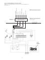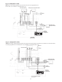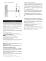
1
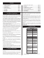
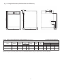
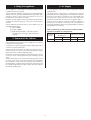
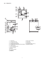
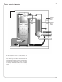
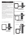
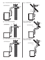
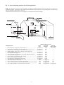
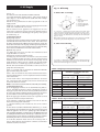
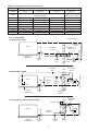
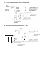
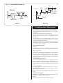
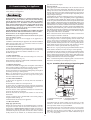
GREENSTAR II HE OIL
12/22
ROOM SEALED BF FLOOR STANDING OIL-FIRED
CONDENSING PRESSURE JET APPLIANCE
INSTALLATION AND
SERVICING INSTRUCTIONS
POWER ON
TEMP
T30.30275.03
GREENSTAR
HE 12/22
LOCK OUT
BOILER OUTPUT
Hot Water and Central Heating
12/22 MINIMUM 12 kW (41,000 Btu/h)
MAXIMUM 22 kW (75,000 Btu/h)
THESE INSTRUCTIONS APPLY TO UK MODELS ONLY
THESE INSTRUCTIONS ARE TO BE LEFT WITH THE APPLIANCE
Contents
1.
2.
3.
4.
5.
6.
7.
8.
9.
10.
11.
12.
13.
14.
15.
16.
Installation Regulations ...........................................Page 2
General Information .................................................Page 2
Technical Data...........................................................Page 2
Siting the Appliance .................................................Page 4
Removal of the Cabinet............................................Page 4
Air Supply..................................................................Page 4
Flue System...............................................................Page 7
Oil Supply ..................................................................Page 10
Heating and Hot Water System...............................Page 13
Electrical ....................................................................Page 14
Installation ................................................................Page 18
Commissioning the Appliance ................................Page 19
Instructions to the User ...........................................Page 20
Routine Cleaning and Inspection............................Page 20
Short Parts List..........................................................Page 23
Fault Finding .............................................................Page 25
system causing the combustion air to be drawn through a duct
from outside. The sealed burner cover gives excellent acoustic
noise reduction and alleviates the need for an air brick to be
located in the boiler room.
1. Installation Regulations
1.1 General installation information and advice may be obtained
from the Oil Firing Technical Association for the Petroleum
Industry (OFTEC). Training courses are also offered by OFTEC,
leading to inclusion on their list of registered engineers.
1.2 The appliance should be installed by a competent person. The
person installing the appliance should be aware of the Health and
Safety at Work Act and take appropriate action to ensure that the
regulations are adhered to. In order to give optimum efficiency
and trouble free operation the appliance should be commissioned
by a qualified engineer. OFTEC recommends the use of registered
engineers for the commissioning of oil-fired burners.
1.3 The manufacturers notes must not be taken, in any way, as
overriding statutory obligations.
1.4 The compliance with a British Standard does not, of itself,
confer immunity from legal obligations. In particular the
installation of this appliance must be in accordance with the
relevant requirements of the following British Standards and
regulations in respect of the safe installation of equipment.
Because the balanced flue system does not rely on the cabinet
panels to form the room seal, combustion readings can be taken
from the test point on the condenser heat exchanger and the cabinet panels can be easily removed during installation thereby preventing any damage.
2.4 The boiler is factory set to the mid-range output and can be
altered, if necessary, by adjusting the burner as specified in Table
2. This appliance is only suitable for use with 28 second Kerosene
heating oil.
NOTE: It is a mandatory requirement of the building
regulations that only 28 second kerosene is used on low level
discharge flues.
3. Technical Data
Table 1
BS 5410: part 1& 2: Code of practice for Oil Fired Boilers.
BS 799: part 5: Specification for Oil Storage Tanks.
BS 7593: Code of Practice for treatment of water in domestic hot
water central heating systems.
BS 5449: part 1: Specification for forced circulation hot water
central heating for domestic premises.
BS 5955: part 8: Specification for the installation of
thermoplastic pipes and associated fittings for use in domestic
hot and cold water services and heating systems.
BS 7291: Thermoplastic pipes and associated fittings for hot and
cold water for domestic purposes and heating installations in
buildings.
BS 7074: part 1: Application, selection and installation of
expansion vessels and ancillary equipment for sealed water
systems.
BS 7671: IEE Wiring Regulations, current edition.
The Building Regulations Part J and L1 England and Wales; Part F
and Part J Section III Scotland; Part L and Part F Northern Ireland.
Local water company bye-laws.
The Control of Pollution (Oil) Regulations.
1.5 To ensure that the installation will perform to the highest
standards, the system and components should conform to those
mentioned in the instructions.
SPECIFICATIONS
Model
POWER SUPPLY
HEATING FLOW
HEATING RETURN
FUEL LINE
MINIMUM FLUE
REQUIREMENT
12/22
230/240V 50 Hz
22mm
22mm
1
/4" BSP
Balanced Flue Kit
Page 8
Below 100°C
30m (98 ft. )
PRIMARY WATER CAPACITY 20 litres (4.4 gal.)
HEARTH TEMPERATURE
MAXIMUM STATIC HEAD
WEIGHT
121 Kg (267 lbs)
BURNER
Electro Oil
Sterling 40
EXIT FLUE GAS
MASS FLOW
2. General Information
2.1 These instructions cover room sealed balanced flue (RS) appliances only.
CONTROL THERMOSTAT
RANGE
50°C minimum
cut in to 80°C
maximum cut out
CONTROL THERMOSTAT
DIFFERENTIAL
5°C
COMBUSTION PRODUCTS
SAFETY THERMOSTAT
BREAK POINT
120 + 0/ – 6°C
IP RATING
2.2 The Worcester Greenstar HE Oil appliance covered in these
instructions has been designed to serve domestic central heating
and hot water requirements ranging from 12 kW to 22 kW.
40 kg/hr
*SEDBUK RATING
20
90.7%
BAND A
* The value is used in the UK Government Standard Assesment Proceedure (SAP) for
2.3 This RS balanced flue appliance forms a fully room sealed
energy ratings for dwellings.
2
Fig. 1. Principal Dimensions (All Dimensions are millimetres)
65
205
89
POWER ON
TEMP
244
374
777
785
LOCK OUT
HE 12/22
858
GREENSTAR
623
585
12/22 Table 2. Electro Oil Bentone Sterling 40 Burner (See Fig. 27)
RS Balanced Flue Appliance
NOMINAL BOILER RATING AT NORMAL OPERATING TEMPERATURE
Fuel
28 Sec. Kerosene
28 Sec. Kerosene
28 Sec. Kerosene
Nozzle
0.40 80°EH
0.45 80°EH
0.50 80°EH
Pump
Pressure
(p.s.i.)
150
150
150
Fuel Flow
Rate
Kg/h
l/h
1.24
1.55
1.46
1.83
1.68
2.10
Flue Gas
Temp.
°C
60
70
80
%CO2
10.5-11.0
11.0-11.5
11.5-12.0
Approx.
Air
Setting
2
3
5
kW
14.7
17.3
22.0
Appliance
Input
Output
Btu/hr
kW
Btu/hr
50,000
14.1 48,000
59,000
16.6 57,000
75,000
21.1 72,000
Note: These figures are given for guidance only, it is essential therefore that the settings are adjusted to give the correct CO2 value.
3
4. Siting the Appliance
6. Air Supply
4.1 The appliance is not suitable for external installation unless
a suitable enclosure is provided.
4.2 The appliance should be positioned on a non-combustible
solid base as near to the flue termination point as possible. Care
should be taken to ensure that the appliance is level; use
packing at the corners where necessary.
4.3 The rear of the appliance must be positioned so that the flue
terminal can safely discharge the flue gases as described in
Section 7.
4.4 The following clearances must be left to allow access for
installation and servicing:
(a) Above 600mm
(b) In front - 600mm
(c) Right and left hand side – sufficient for panel
removal and access to pipe connections where
required.
6.1 The appliance does not require a separate vent for
combustion air.
6.2 Installation in cupboards or compartments requires
permanent vents for cooling purposes, one at high level and one
at low level, either direct to outside air or to a room. Both vents
must pass to the same room or be on the same wall to the
outside air. The minimum air vent free area is given in Table 3.
6.3 There must be sufficient clearance around the appliance to
allow proper circulation of ventilation air. The clearances
required for Installation and Servicing will normally be adequate
for ventilation. See Section 4.4.
Table 3. Minimum Air Vent Free Area for Room Sealed
appliances installed in a compartment.
Appliance
model
5. Removal of the Cabinet
12/22
For installation and servicing of the appliance the cabinet
should be removed as follows:
5.1 Remove the cabinet top panel by lifting squarely upwards to
release the four stud connections.
5.2 Remove the front panel by pulling the upper part of the
panel forwards to release the studs and lifting the panel
upwards to release it from its supporting ledge.
5.3 Remove electrical cover plate by unscrewing the two screws
at the rear of the connector protecter plate and hinge up and
away.
5.4 The control box can be removed by undoing the two screws
in the top access cover, two screws in the front, two ball studs in
the top and the screw in the heat exchanger. The thermostat
phials should be carefully removed from the phial pocket and
the control box placed in a safe place taking care not to kink the
thermostat capillary tubes.
4
Ventilation to room or
internal space
High Level
187cm2
Low Level
187cm2
Ventilation to outside
High Level
93.5cm2
Low Level
93.5cm2
Fig. 2. Components
16
14
13
15
13
12
7
17
3
1
13
14
15
1
3
12
2
4
11
16
5
6
10
6
7
8
9
1)
Control panel
13) Auto air vent connection
14) Heating flow
2) Condenser drain point
3) Secondary heat exchanger
15) Heating return
4) Combustion product test point
16) Combustion products flue exit
5) Secondary heat exchanger inspection/cleaning port 17) Electrical cover plate
6) Condensate drain
7) Heat exchanger drain point
8) Burner air inlet pipe
9) Oil Burner
10) Lock out reset button
11) Sight glass
12) Boiler shell
5
Fig. 3. Principle of Operation
Heating
circuit
return
Heating
circuit
output
The Greenstar HE Oil 12/22 is a sealed exhaust circuit condensation boiler.
Air is drawn in by the burner's fan from outside the
appliance through the hose connected to the air inlet
and combustion product evacuation concentric tube.
The boiler shell equipped with a system of removable baffles, is linked to a stainless steel secondary
heat exchanger located directly on the heating
return.
6
Fig. 5. Extended Horizontal Flue
7. Flue System
A flue system provided by Worcester Bosch, must be fitted in
accordance with BS5410:Part 1 and the Building Regulations.
The appliance is supplied ready for installation to a balanced
flue system by the simple addition of one of the flue terminal kit
options shown in Figs. 4 to 13.
Details of the installation procedure are included in the Flue
Terminal Instructions supplied with the terminal kit.
125mm
125mm
(5")
(5")
7.1 Siting the flue terminal
1. The flue terminal must be located in a suitable position, as
shown in Fig.14, such that the products of combustion can be
freely dispersed without the possibility of the gases entering the
dwelling or that of a neighbouring dwelling.
2. Discharge of flue gases into car ports or narrow passageways
is not recommended.
3. The terminal must not cause an obstruction nor the discharge
cause a nuisance as a result of either flue gases or terminal
noise.
4. If a terminal is fitted less than 2 metres above a surface to which
people have access, a suitable terminal guard must be fitted.
A suitable guard is available from Worcester Heat Systems, Part
Number 7 716 190 009, or alternatively a proprietary terminal
guard may be used provided it leaves 75mm clearance all
around the terminal.
The guard should have suitable corrosion resistance due to the
acidic content of the flue gases.
1000 - 5000mm
1000 - 5000mm
(39.09")
(39.09" -- (195.45")
195.45")
Fig. 6. Horizontal Flue with one 90° Bend
125mm
125mm
(5")
5. The terminal guard must be evenly spaced about the flue
terminal and secured using screws so that the terminal guard
can be removed for maintenance to the flue terminal..
6. In certain weather conditions. The terminal may steam and
siting where this could cause a nuisance should be avoided.
7. Take care to ensure that combustion products do not enter
ventilated roof voids.
500
500 -- 4000mm
4000mm
(19.7" -- (157.5")
157.5")
(19.7")
Fig. 7. Horizontal Flue with two 90° Bends
Fig. 4. Standard Horizontal Flue
2
Total straight length 1+2
Total straight length 1+2
must
notnotexceed
must
exceed 3000mm
3000mm
125mm
125mm
(5")
(5")
125mm
125mm
(5")
(5")
1
1000mm
1000mm
(39")
(39")
180mm
7
Fig. 8. Flue with one 90° and two 45° Bends
Fig. 11. Vertical Flue
2
Total
straight length 1+2+3
Total straight length 1+2+3
must
not
3000mm
must
notexceed
exceed 3000mm
300mm
minimum
125mm
125mm
(5")
(5")
3
125mm
125mm
(5")
(5")
Diameter
Diameter
1150 - 5000mm
1150
- 5000mm
1
180mm
180mm
Fig. 12. Vertical Flue with
two extra 90° Bends
Fig. 9. Flue with two 90° Bends
2
Total
straight
1+2
Total
straight length
length 1+2
must
not
must
notexceed
exceed 3000mm
3000mm
300mm
minimum
2
Total straight
length
Total straight
length1+2+3
1+2+3
mustexceed
not exceed
3000mm
must not
3000mm
125mm
125mm
(5")
(5")
125mm
(5")
125mm (5") Diameter
3
1
1
180mm
180mm
Fig. 13. Vertical Flue with
two extra 45° Bends
2
Fig. 10. Flue with one 90° and two 45° Bends
Total
length
1+2+3
Total straight
straight length
1+2+3
must
3000mm
mustnot
not exceed
excced 3000mm
2
Total straight length 1+2
Total
straight4000mm
length 1+2+3
must not
exced
125mm
125mm
(5")
(5")
3
must not exceed 4000mm
125mm
(5")
125mm (5") Diameter
3
1
1
180mm
180mm
8
300mm
minimum
Fig. 14. Flue terminating positions for oil-fired appliances
NOTE: The dimensions given are for general guidance only. Other surrounding buildings or objects may affect the clearance of
combustion products. An alternative flue terminal position should be sought when there is any possibility of a nuisance being
caused by inadequate dispersal of flue products.
Terminals should be positioned so as to avoid products of combustion entering into buildings.
P
O
M
Boundry
M
N
C.D.
F
B
J
A
Window
H
K
E
Boundry
Flue
Terminal
G
F
F
L
Minimum Distance (mm)
Open
Low-Level
Vertical
Flue
Discharge
Balanced Flue
Terminal Position
A
B
C
D
Directly below an opening, air brick, window, etc. ..........................................
Horizontally to an opening, air brick, window, etc. ........................................
Below a gutter or sanitary pipe if combustible material protected. ..............
Below a balcony, eaves, gutter or drainage without protection
to combustible material. ......................................................................................
E From vertical sanitary pipework.. .......................................................................
F From an internal or external corner or boundry along side terminal. ..........
G Above ground or balcony level. ..........................................................................
H From a surface or boundry facing the terminal. ..............................................
J
From a terminal facing the terminal. .................................................................
K Vertically from a terminal on the same wall. ...................................................
L Horizontally from a terminal on the same wall. ..............................................
M Above an intersection with the roof. .................................................................
N From a vertical structure on the side of the terminal......................................
O Above a vertical structure less than 750mm from the side of the terminal.
P From a ridge terminal to a vertical structure on the roof................................
9
Not allowed
Not allowed
Not allowed
Not allowed
Not allowed
Not allowed
Not allowed
Not allowed
Not allowed
Not allowed
Not allowed
600
750
600
1500
600
600
75
600
300
300
300
600
1200
1500
750
Not applicable
Not applicable
Not applicable
Not applicable
Not allowed
''
''
''
''
''
''
''
''
''
732
750
732
Not applicable
8. Oil Supply
Fig. 15. Oil Pump.
A. Danfoss BFP 11 Oil Pump.
(See Fig. 16).
8.1 Plastic or steel tanks should be installed to BS5410.
A steel tank should also conform to BS799: part 5 and be arranged
with a slope of 1 in 24 away from the outlet valve with a sludge
cock at its lower end.
8.2 Do not use galvanised steel tanks or pipework for the oil
supply system.
8.3 Do not use soldered joints on the oil supply pipework as this
could cause a hazard in the case of a fire.
8.4 The burners on all appliances are supplied so as to be
connected to a single pipe gravity feed system. Details of how to
convert the burners to a double-pipe sub-gravity feed system
are shown in Fig. 15.
8.5 Oil Supply System
(a) Single Pipe System
If a single pipe system is employed then the tank must be positioned
such that the oil level does not exceed 4 metres above the level of
the burner oil pump and in addition the oil level must be at least 0.3
metres above the level of the oil pump. Should it prove impossible to
site the tank below the 4 metres maximum oil level a head breaking
device must be installed between the tank and the burner.
(b) Double Pipe System
If a double pipe system is used then the maximum suction
height allowable is 3.5 metres.
(c) Single Pipe Suction Lift with De-aerator
If a single pipe suction lift with a de-aerator is used, the oil tank
must be positioned below the burner. An inlet and return loop
should be created between the de-aerator and oil pump. The oil
pump should be connected as for a double pipe system. Details
of how to convert to a double pipe system are shown in Fig. 15.
Oil inlet and return flexible hoses should be connected to the oil
pump inlet and return ports.
Table 6 is a general guide to determine the maximum allowable
pipe run when using a de-aerator.
Table 6 does not override the de-aerators manufacturers instructions and should only be used in conjunction with the manufacturers instructions.
If a non-return valve is not incorporated within the de-aerator
unit, a non-return valve should be fitted in the oil line between
the oil tank and the de-aerator.
NOTE: If a de-aerator is used it should be fitted externally to the building.
8.6 Oil Supply Pipework
a) The oil supply pipe diameter can be determined using Tables 4,
5 and 6 depending on whether a single or double pipe system or
single pipe system with de-aerator is being installed. Selection of
the correct pipe diameter will depend on the position of the oil storage tank relative to the burner and the length of the pipe run.
b) The oil supply pipe should be laid as level as possible to avoid
air pockets and unnecessary friction losses.
c) The following components should be fitted in the fuel line
between the storage tank and burner:
1. A manual isolating valve installed as close to the tank as
possible.
2. A fire valve in accordance with BS5410 as shown in Fig. 16. The fire
valve should be fitted externally with a fire detection element located
within the appliance case. Use of a capillary type valve will allow a
neat and simple installation. A suitable valve is the KBB manufactured
by Teddington Controls Limited. Alternatively a fusible link or electrical system may be used. Under no circumstances should a combination isolating/fire valve be used as the sole fire protection device.
3. An oil filter should be fitted close to the oil storage tank. If
there is doubt about the internal oil line condition, a further filter
should be fitted near the boiler.
3
6
5
4
A
1. Inlet
2. Return
3. Bleed and pressure
gauge port
4. Vacuum gauge port
5. Pressure adjustment
6. Nozzle outlet
1
2
To convert to a double pipe system: Remove the pump front
cover, remove the changeover screw (A) nearest to ports 1 and 2,
and the horseshoe washer underneath. Replace the changeover
screw back into the threaded hole. Connect the flow and return
pipes to 1 and 2.
Note: When removing the pump front cover ensure that a suitable
receptacle is placed below the pump to catch the oil residue.
B. Suntec AS47C Oil Pump.
3
4
5
B
3
1
A
To convert to a double pipe system, remove the return port plug (2)
and insert the grub screw (A) provided into the threaded hole (B).
Connect flow and return pipes to (1) and (2).
2
TABLE 4 Single Pipe Gravity Feed System
HEAD (metres)
MAXIMUM ALLOWABLE PIPE RUN
(metres)
0.5
1.0
1.5
2.0
2.5
3.0
3.4
4.0
8 mm inside dia. pipe 10 mm inside dia. pipe
(10 mm O.D. copper)
(12 mm O.D. copper)
12
30
25
69
37
91
49
100
62
100
74
100
87
100
99
100
TABLE 5 Double Pipe Sub-Gravity Feed System
10
HEAD (metres)
MAXIMUM ALLOWABLE PIPE RUN
(metres)
0
0.5
1.0
1.5
2.0
2.5
3.0
3.5
8 mm inside dia. pipe 10 mm inside dia. pipe
(10 mm O.D. copper)
(12 mm O.D. copper)
50
100
44
100
38
95
32
80
26
66
20
50
14
37
8
22
TABLE 6 Single Pipe Suction Lift with De-aerator
MAXIMUM ALLOWABLE PIPE RUN FROM TANK TO DE-AERATOR (metres)
5.0 (kg/h)
100
95
80
70
60
45
35
25
6 mm inside dia. pipe
(8 mm O.D. copper)
55
45
40
35
30
25
15
10
10.0 (kg/h)
10.0 (kg/h)
26
23
20
17
14
11
8
5
8 mm inside dia. pipe
(10 mm O.D. copper)
100
100
90
75
65
50
35
20
Fig. 16. Oil Supply.
Wall
Full base
(for plastic tanks)
Filter
Isolating
valve
Isolating
valve
Non return
valve
(b) Double pipe system.
Oil tank
Fire detection
element
Fire valve to
BS 5410
Filter
Non return
valve
Isolating
valve
Wall
Fire detection
element
Isolating
valve
Isolating
valve
Burner
Burner
150 mm
Full base
(for plastic tanks)
Isolating
valve
Fire valve to
BS 5410
Wall
(c) Single pipe lift system with de-aerator.
Fire detection
element
De-aerator
Oil tank
Filter
Fire valve to
BS 5410
Full base
(for plastic tanks)
H = 0.3 m (1 ft) minimum
Oil tank
Paper element
oil filter
Isolating
valve
Burner
Isolating
valve
11
H = 4 m (13 ft) maximum
Maximum oil level
(a) Single pipe system
H = 3.5 m (11.5 ft) maximum
0
0.5
1.0
1.5
2.0
2.5
3.0
3.5
2.5 (kg/h)
H = 3.5 m (11.5 ft) maximum
Fuel
Flowrate
HEAD
(metres)
Fig. 17. Typical Open Vent Fully Pumped System (Honeywell ‘Y’ plan).
Fig. 18. Typical fully pumped sealed system (Honeywell ‘Y’ plan).
Automatic
air vent
Domestic hot
water
cylinder
Diverting
valve
Safety valve
Pressure
gauge
Pump
Boiler
Expansion
Vessel
To system filling device (see Fig.14)
Automatic bypass valve to be fitted
where thermostatic radiator valves
are fitted on all radiators
12
N.B. A drain cock should be
installed at the lowest point of
the heating circuit
Radiator
Fig. 19. System filling and make-up
Heating
return
Make up
vessel
Auto air
vent
Non return
valve
Stop
cock
30mm (12in) min.
above highest
point of the system
Fill point.
Heating return
Method 1
Method 2
9. Heating and Hot Water System
9.1 The appliance is suitable for connection to all conventional indirect hot water systems utilising an indirect double feed cylinder.
9.2 The flow and return connections are located at the rear of
the appliance.
9.3 There is no requirement for a system bypass.
9.4 The pressure jet burner fitted to the appliance has full
automatic control and hence there is no requirement for heat
leak radiators.
9.5 The primary system should be flushed and treated in
accordance with the recommendations of BS 7593:1992 before
the system is handed over to the user.
9.6 The pump should be set in accordance with the heating load
requirements to give a flow and return differential temperature
of 11°C under full load conditions.
Open Vent Primary System.
(See Fig.17).
The following points are for guidance only. The system
installation should be carried out in accordance with BS 5449:
Part 1.
1. System Pipework
The first metre of pipework from all appliance connections must
be in copper; afterwards copper or plastic pipe can be used. The
plastic pipe must be manufactured to BS 7291 and installed to
BS 5955 part 8. It is important to protect the system
components; the plastic pipe specified must be resistant to the
ingress of oxygen.
2. Feed and Expansion System
The feed and expansion pipes must rise continuously from the
appliance and must be of the minimum diameter shown in Fig 17.
The cistern must be arranged to provide a minimum static head
of 1 metre above the top of the highest point in the heating
circuit.
3. Filling and Venting
Air in the appliance is expelled through the vent pipe or
dissipated into the system. Manual air vents should be fitted at
any high points in the system.
There is a connection on the appliance for connecting an auto
air vent.
Sealed Primary System
The appliance is supplied with a manual reset thermostat and is
suitable for use with a sealed primary system.
General
The system should be installed in compliance with the
13
requirements of BS5449: Part 1. The boiler must be fitted with a
spring loaded safety valve set to operate at 3 bar (45 psi) and
the pipe connections made throughout the system must be
capable of sustaining a pressure of up to 3 bar.
Copper pipework must be used through out when installing the
appliance on a sealed system.
The following is a list of major items which must be fitted to the
system:
1. Safety valve – 3 bar
2. Pressure gauge – 0 to 4 bar.
3. Expansion vessel
4. Automatic air vent.
If the system is fully pre-wired at a junction box remotely from
the boiler it can be connected to the boiler. The diagram shows
connection details of two proprietary systems (Honeywell and
Invensys).
The WHS facia mounted programmer can be fitted instead of an
external timer to the remote junction box. Remove the link plug
(8 to 9) and connect the programmer plug into the time clock
connector. Connect terminal 1 from the boiler terminal block to
the 'HOT WATER ON' on the remote 10 way junction box.
Connect terminal 2 from the boiler terminal block to the
'HEATING ON' on the remote 10 way junction box..
NOTE: A “Y” Plan requires a live feed from 'HOT WATER OFF '
switch position. In order to achieve this, using a WHS programmer, remove the orange wire from terminal 9 and pull back
through the tie wraps. Ensure the brown wire is firmly secured in
terminal 9. Connect the orange wire to terminal 6 and connect
terminal 6 on the boiler terminal block to the 'HOT WATER OFF'
connection at the remote 10 way junction box.
10.8 Honeywell “S” Plan
(See Fig. 23).
The “S” plan provides complete control on installations having
pumped circulation to both the domestic hot water and radiator
circuits.
The domestic hot water and radiator circuits are independently
controlled by two motorised valves via a cylinder thermostat
and a room thermostat. Both thermostats switch the water
circulator and the boiler on and off.
10.9 Honeywell “Y” Plan
(See Fig. 24).
The “Y” Plan provides complete control on installations having
pumped circulation to both the domestic hot water cylinder and
radiator circuits.
The domestic hot water and radiator circuits are controlled by a
3 port motorised valve via a cylinder thermostat and a room
thermostat. Water flow is diverted to either circuit or to both
circuits at the same time. Both thermostats switch the water
circulator and the boiler on and off.
Note: The “Y” plan requires a live feed from the hot water “off”
switch position. In order to achieve this, using a WHS
programmer, remove the orange wire from terminal 9 and pull
back through the tie wraps. Do not attempt to cut the tie wraps.
Ensure that the brown wire is firmly secured in terminal 9.
Connect the orange wire to terminal 6.
10.10 Frost Protection
(See Fig. 25).
For full frost protection a single pole double switch thermostat
should be fitted so that both the boiler and the circulating pump
circuits are energised under frost conditions. Frost protection
will be lost if there is no power supply to the boiler.
10. Electrical
(See Figs. 20 to 25).
10.1 The wiring between the appliance and the electrical supply
shall comply with current IEE Wiring Regulations and any local
regulations which apply.
10.2 To gain access to the electrical terminal strip.
1. Isolate the mains electrical supply.
2. Remove the cabinet top panel by pulling squarely
upwards.
3. Release the two screws securing the terminal connector
protector plate and remove.
10.3 Mains Wiring
Mains supply – 230V AC ~ 50 Hz 5A External Fuse to BS1362.
LIVE - Brown, NEUTRAL - Blue, EARTH - Green/Yellow
Mains Cable: 0.75mm2 (24 x 0.20 mm) to BS 6500 Table 16.
The boiler and system controls must be supplied using a single
fused supply.
The mains supply cable should be connected into the terminals
marked L (Live), N (Neutral) and E (Earth) on the appliance
terminal strip and securely held in the cable clamp located in
the left-hand side of the electrical tray base. Feed the cable
between the side panel and the boiler insulation jacket and
route to the connection point avoiding any hot surfaces.
The appliance must be earthed.
10.4 Programmer
(See Fig. 21).
A plug in, colour co-ordinated, 2 channel electronic programmer
is available from Worcester Heat Systems Limited. Full
instructions covering installation and operation of the
programmer are included with the kit. (See Fig. 21a)
The programmer will give fully independent central heating (CH)
and hot water (HW) programmes when the switch on the rear of
the unit is set to P.
If an external programmer is to be fitted to the boiler the link
plug should be removed from the programmer terminal strip.
(See Fig. 21b). The LIVE, NEUTRAL and EARTH wires should be
connected to the LIVE, NEUTRAL and EARTH terminals on the
main terminal strip and the switched lines connected to
terminals 1 and 2.
NOTE: The mains supply cable should not be connected to an
external time switch when a frost thermostat is fitted to the
Greenstar HE standard wiring block.
NOTE: Under no circumstances should the timer be connected
to a separate electrical supply. Safety is assured from a single
fused supply to the boiler.
10.5 Safety Check
In the event of an electrical fault after the installation of the
appliance, the electrical system shall be checked for short
circuits, fuse failure or incorrect polarity of connections.
10.6 Pre-wired Remote “Y” or “S” Plan systems
(See Fig. 22).
14
Fig. 20. Wiring Diagram (Standard).
Mains supply 230V 50Hz
5 Amp.
E N L
Earth
Stud
Brown
Green/Yellow
Blue
White
Grey
Blue
Green/Yellow
Brown
Flue Overheat
thermostat
Manual reset
thermostat
Time clock
white
connector
L N E E N 1 2 3 4 5 6
7 8 9 10
Brown
Blue
Green/Yellow
Brown
Orange
Brown
Blue
Brown
Brown
Black
Blue
Mains on
neon
(1)
(C)
Control
thermostat
Lockout
neon
Plug in
1 2 3 4 5 6 connector
1 2 3 4 5 6
Green/Yellow
Black
Brown
Blue
Plug in connector
1 2 3 4 5 6 7
N
89
E
Satronic control box
TF832.3
Fig. 21. Programmer Connections
(a) Internal Programmer
7 8 9 10
(b) External Programmer
Grey
White
Brown
Blue
Pre-wired time clock
terminal strip socket
(Located in boiler
electrical cover).
Brown
Grey
White
Pre-wired time clock
terminal strip plug
(Connected to time
clock leads).
CH
HW
Blue
Programmer
15
Fig. 22. Pre-wired Remote ‘Y’ Plan or ‘S’ Plan.
Remote Pre-wired
Junction Box
External Timer
Pump
System Water Valves
Room Stat
Tank Stat
Mains Wiring
230V 50Hz (5 amp fuse)
NOTE: When using a WHS programmer set the switch on the rear of the programmer to ‘P’.
Remove link 1 to 3
NOTE: If a frost thermostat is required it
can be wired to the remote junction box.
NOTE: The 10 way junction box must be
a terminal block type and current rated
to at least 5 amps.
10 WAY JUNCTION BOX
OUTSIDE BOILER
INSIDE BOILER
Earth
Neutral
Permanent Live
Green/Yellow
Blue
Brown
Black
Switched Live
L N E E N 1 2 3 4 5 6
7 8 9 10
Optional
Worcester
Programmer
HEAT SYSTEMS
HOT
WATER
ADVANCE
SELECT
Burner Socket
16
OFF
TWICE
ONCE
ON
LOCK SET?
TUE
PM
YES
OFF
TWICE
ONCE
ON
HEATING
ADVANCE
SELECT
Fig. 23. Honeywell ‘S’ Plan.
NOTE: When using a WHS programmer set the switch on the rear of the programmer to ‘P’.
Remove link 1 to 3 and link 2 to 4 and make link 3 to 4
N
Room thermostat
Heating Valve. Honeywell V4043H
Brown
Grey
Brown
Pump
Blue
Blue
Green/Yellow
Blue
Brown
Green/Yellow
Orange
E NL
7 8 910
L N E E N 1 2 3 4 5 6
Grey
Blue
Green/Yellow
L
N
E
Orange
Hot Water Valve
Honeywell V4043H
Brown
Cylinder
Thermostat
Optional
Worcester
Programmer
HEAT SYSTEMS
HOT
WATER
ADVANCE
SELECT
OFF
TWICE
ONCE
ON
TUE
LOCK SET?
PM
OFF
TWICE
ONCE
ON
HEATING
ADVANCE
YES
SELECT
Burner Socket
Fig. 24. Honeywell ‘Y’ Plan.
NOTE: When using a WHS programmer remove the orange wire from terminal 9 and connect to terminal 6. Set the switch on the
rear of the programmer to ‘P’. Remove link 1 to 3 and link 2 to 4 and make link 3 to 5.
Blue
Room thermostat
N
Pump
E NL
2
3 4
5
7 8 9 10
6
Orange
L N E E N 1
Grey
White
Brown
Blue
Green/Yellow
Blue
Brown
Brown
E
N
Green/Yellow
Blue
Grey
Orange
White
C
2
1
HEAT SYSTEMS
HOT
WATER
ADVANCE
SELECT
OFF
TWICE
ONCE
ON
LOCK SET?
TUE
PM
YES
Burner Socket
17
OFF
TWICE
ONCE
ON
HEATING
ADVANCE
SELECT
Mid Position Valve
Honeywell V4073A
Cylinder
Thermostat
Optional
Worcester
Programmer
(c) Single pipe system oil supply pipe.
1. Bend a piece of 10mm or 12mm copper tube (as selected) to
the correct profile to allow the pipe to be fed down the side of
the appliance. The pipe may be routed along either the right or
left hand side of the boiler as required. When using 12mm pipe
fit a 12mm to 10mm compression coupling and connect to the
valve with a short piece of 10 mm pipe, otherwise connect direct
to the valve.
Note: never use soldered joints on oil supply pipes as this could
cause a hazard in the case of a fire.
2. Route the pipe back to the oil supply tank ensuring that it is
hard against the boiler, to allow installation of the side panel.
3. With the isolating valve in the correct orientation tighten the
back-nut.
4. Turn the isolating cock fully clockwise to close the valve.
5. Open the main oil supply valve at the tank and check for any
leaks.
6. Place a suitable container below the bulkhead fitting and
open the valve.
7. Draw off at least 2.5 litres of oil until a steady flow of clear
uncontaminated oil can be seen and turn off the isolating valve.
Note: This method may not be possible on some installations
where a sub-gravity system is used. Where this problem arises
bleed the system using the oil pump as described in Section 12
and remove and clean the oil pump filter to remove any debris
collected as a result of installation.
11.6 Replace the electrical control panel and side panels in
reverse order to the removal procedure of Section 5 and connect
the electrical supply as described in Section 10.
11.7 Condense drain connection
When connecting the condensate drain to the waste water
drain, it is essential to maintain a downwards slope towards the
waste drain.
Note: The maximum production of condensate is 1.5 L/h. This
flow rate does not require any specific treatment.
Fig. 25. Frost Protection.
11. Installation
11.1 After unpacking the appliance it is recommended that the
top and front cabinet panels are removed, as described in Section
5, and stored in a safe place to avoid damage during installation
and allow easy inspection for any leaks after the system has
been filled.
11.2 Remove the burner as described below and store in a safe
place until the appliance is ready for commissioning.
1. Remove the air tube from the burner by loosening the jubilee
clip and pulling the tube up and away.
2. Remove the 13mm nut at the top of the burner and pull the
burner out, taking care not to put any tension on the electrical
cable.
11.3 Flue system installation.
Install the appliance flue system as described in Section 7.
11.4 Heating system installation.
Before the appliance is fitted to the heating system
flush the system and mains water supply.
1. Plumb the boiler into the central heating system.
2. Check that all unused sockets have been plugged.
3. Fit the auto air vent to the boiler.
4. Fill the system and vent all radiators and high points to
remove air from the system.
5. Check the boiler and all pipework connections for leaks.
11.5 Oil supply installation.
(See Fig. 16).
NOTE: Never route the oil supply pipe/hose directly below the
combustion chamber base.
NOTE: Connection of rigid copper pipe to the oil pump is not recommended. Connection to the oil pump should be made with
flexible oil hoses.
(a) Single pipe suction lift with de-aerator.
For connection of single pipe suction lift with de-aerator follow
the procedure as for a double pipe system as described below.
(b) Double pipe system oil return pipe.
1. fit the oil return pipe, from the tank, down the left hand side
of the boiler along the base. Terminate the end approximately
200mm from the front of the base.
2. Connect a flexible hose, of the same type as the one supplied, to
the pipe using a suitable adaptor.
Ensure that the connections are properly sealed.
3. Fit the oil supply pipe as described in the following section.
18
port. Re-lock the bleed port.
Two Pipe System
A two pipe system will automatically vent the air back to the oil
tank. Turn on the boiler thermostat and allow the burner to run
through to lockout. Wait two minutes and reset the burner control box. Repeat the procedure untill the burner fires and runs in
a steady state. This may take several attempts depending on the
oil pipe length and height.
12.10 Adjust the air shutter and pump pressure to the settings recommended in Table 2. After a pre-ignition period of approximately
15 seconds the burner should ignite. Flame sensing is carried out by
means of a photocell mounted in the burner body. Should the boiler
fail to establish a normal firing pattern (or should flame failure occur
during running), the absence of a flame is sensed and the control box
is monitored to a safe lockout condition and the boiler is shut down.
The lockout indicator light in the boiler control panel will illuminate
indicating that the burner has gone to lockout. In this instance wait
two minutes and press the red lockout reset button mounted in the
burner control box. Another start sequence is then initiated. Repeat
the procedure until a flame is established.
12. Commissioning the Appliance
Ensure that no foreign matter is left in the system as this could
cause damage to the appliance.
Benchmark Water Treatment: For optimum performance after
installation, this boiler and its associated central heating
system should be flushed in accordance with the guidelines
given in BS7593:1992 - Treatment of water in domestic hot
water systems. Full instructions are supplied with proprietary
cleansers sold for this purpose. If an inhibitor is to be used
after flushing, it should be used in accordance with the
inhibitor manufacturers instructions.
Suitable flushing agents and inhibitors are available from Betz
Dearborn Tel: 0151 4209563 and Fernox Tel: 01799 550811.
Instructions for use are supplied with these products.
Note: Persistent lockout when running indicates a fault and a
Service Engineer should be consulted.
IMPORTANT: Any system cleanser must be flushed from the system
before an inhibitor is added.
12.11 Run the boiler for approximately 3 minutes and switch
off checking that there is no after-spurting from the nozzle. This
can be detected by oil saturation on the blast tube. If afterspurting occurs remove the burner from the boiler, unscrew the
nozzle, and while holding the burner in a vertical position, fill the
nozzle holder with oil. Refit the burner and continue to run the
boiler for three minute periods until after-spurting stops.
12.1 Check that the electrical supply to the appliance is
switched off.
12.2 When commissioning the appliance after initial installation
follow the procedure from 12.3, otherwise remove the burner
first as described in Section 14.3.
12.3 Prepare the heating system
1. After initial installation and checking for leaks, as previously
described, drain down the system sufficiently to add a flushing
agent. Flush the system in accordance with BS 7593:1992.
2. Refill the system.
Note: Use of a “T” piece pressure gauge manifold will increase the
oil line volume and hence increase the degree of after-spurting.
12.12 Run the boiler for a further 15 minute period and then finally fine tune the air shutter setting to give the CO2 level specified in
Table 2. During this period some smoke will be emitted due to the
burning of the organic binder in the base insulation board. Smoke
readings will therefore be inaccurate at this point.
12.4 Check the Burner
1. Check that the nozzle and electrode settings are correct for
the relevant burner. (See Fig. 27).
2. Check that the nozzle lies central with the combustion head hole.
3. Check for any visible defects.
Note: A combustion product sampling point is located on the
front of the condensing heat exchanger (see Fig. 26).
Fig. 26. Secondary heat exchanger inspection ports
12.5 Replace the burner
1. Connect the flexible oil supply hose and tighten sufficiently to
form a good seal. Where a double pipe system is being used connect the oil return flexible hose to the return pipe fitting.
2. Insert the burner into the burner mounting flange and tighten
the locking nut using a 13mm spanner.
Note: It is important that a good seal is made between the
burner and the boiler to prevent the escape of the flue gases
from the combustion chamber.
1
4
12.6 Check the installation
1. Check that the appliance is correctly wired as described in
Section 10.
2. Check that the baffles are correctly located.
3. Check that the combustion product high limit thermostat
phial is correctly located in the thermostat pocket positioned in
the top front of the condensing heat exchanger.
4. Check that the water high limit thermostat is located in the
pocket on the main heat exchanger.
5. Check that all of the air-ways to the burner are clear of any
obstruction.
12.7 Fit a pressure gauge and manifold to the burner pump at
the point indicated in Fig. 15.
12.8 Turn on the electricity to the appliance.
3
1
4
3
1
2
1. Inspection/cleaning port
3. Washer
12.9 Bleed the burner
3
4
2. Combustion test point
4. Test point screw
12.13 Check that the smoke reading is in the range 0-1. If this
cannot be achieved then check that the burner head is set
correctly and the nozzle is in good condition.
Single pipe systems only
Release the fuel bleed port on the manifold and place a suitable
receptacle beneath. Turn on the boiler thermostat. Set the
programmer to heating and hot water and allow the burner to
run through to lockout. Wait two minutes and reset the burner
control box. Repeat the procedure at least three times or until a
steady stream of oil, without air, is exhausted from the bleed
12.14 Check that the flue temperature does not exceed the
value specified in Table 2. If this is the case then check that the
baffles are correctly located. If the baffles are correctly located
then reduce the pump pressure since nozzle variations of up to
+ or – 15% may occur.
19
12.15 Remove the oil pressure gauge and manifold and check
all oil system joints for any signs of leakage.
14. Routine Cleaning and Inspection
12.16 Allow the burner to run for a further five minutes and
then recheck the CO2 level and adjust the air setting if required.
Check that the smoke number is in the range 0-1. Repeat the
fine tuning procedure if found necessary.
14.1 The following should be carried out at least once per year
to ensure efficient, trouble free operation.
1. Carry out a pre-service check noting any operational faults.
2. Check and clean the burner.
3. Check and clean the air intake tube and the air intake grille at
the end of the terminal.
4. Check and clean the baffles.
5. Check and clean the heat exchanger surface.
6. Check the heat shield.
7. Check the combustion chamber base insulation board.
8. Check and clean the secondary heat exchanger and baffles.
9. Check that the flue system is unobstructed and clean as necessary.
10. If the appliance has been installed in a compartment check
that the ventilation areas are clear.
11. Clean all oil filters.
Some of the servicing points are covered more fully in the
following instructions:14.2 Pre-Service Check
1. Remove the cabinet front and top panels as described in
section 5 .
2. Operate the appliance and system, noting any faults which
may need to be corrected during the service.
14.3 Cleaning the Burner
IMPORTANT: Disconnect the electrical supply at the mains
before commencing any servicing. Turn off the oil at the service cock.
1. Remove the burner.
(a) Isolate the oil supply.
(b) Remove the 13mm nut at the top of the burner and pull the
burner out, taking care not to put any tension on the electrical
cable.
12.17 Refit the cabinet top and front panels in the reverse order
to that described in Section 5.
12.18 When the heating circuit has reached full operating
temperature check the whole system for any leaks.
12.19 Add a suitable proprietary corrosion inhibitor such as
Fernox or Sentinel. This will inhibit corrosion, protect the circulating pump and valves reducing the possibility of "kettling" noises
resulting from deposits of scale and sludge in the boiler. Refer to
the product manufacturers instructions for further information.
13. Instructions to the User
13.1
Hand the users instructions and Benchmark Log
Book to the user or purchaser for retention and instruct them in
the efficient and safe operation of the appliance and the heating/hot water system.
13.2 Advise the user or purchaser of the precautions necessary
to prevent damage to the heating/hot water system and to the
building in the event of the heating system remaining
inoperative during frost conditions.
13.3 Finally advise the user or purchaser that for continued
efficient and safe operation of the appliance it is important that
adequate servicing is carried out by a qualified engineer at least
once per year.
Worcester Heat Systems Limited will be pleased to discuss and
offer a comprehensive maintenance contract.
13.4 Set the system controls to the users requirements.
Fig. 27. Burner.
ELECTRO OIL BENTONE STERLING
BURNER
BURNER HEAD
4,7-5,7
(-0,5)-(+0,5)
2,5-3,1
7,0-8,0
20
14.6 Clean the Boiler (See Fig. 29)
1. Remove the boiler top access plate (3) by releasing the bolts
(2) with a 6mm Allen key and check the fibreglass rope seal.
Replace the seal if necessary.
2. Remove the flue deflector (4).
3.Remove the main baffle assembly (5), clean and check its
condition. Replace if considered to be badly corroded.
4. Thoroughly clean all of the heat exchanger surfaces using a stiff
wire brush and vacuum clean all loose debris from the combustion
chamber. Take care not to damage the base insulation!
5. Check the heat shield.
6.Check the condition of the combustion chamber base
insulation and replace if there is any sign of significant damage.
7. Check and clean the flue.
8. Reassemble all parts and be sure:
not to reverse them
to position the flue deflector with its
locating screw towards the front of the
boiler.
to position the cast iron plate against marker
opposite the locating screw.
2. Clean the fan impeller using the following procedure:
(a) Remove the air adjustment cover.
(b) Separate the main body of the burner from the burner front
by removing the M6 allen screw (located beneath the air
adjustment screw), using a 5mm allen key.
(c) Note the position of the air damper adjustment and check
the air damper moves freely.
(d) Check the air path to the burner head is clear.
(e) Clean both sides of the fan impeller and remove any debris
from the burner housing.
(f) Check the impeller rotates freely.
(g) Re-assemble the components.
Fig. 28. Mechanical Shut-off Valve.
Fig. 29. Boiler shell and baffles.
3
2
2
2
2
4. Inspection of Mechanical Shut-off Valve. (See Fig. 28)
a) Remove the nozzle.
b) Fasten an M5 screw, with a minimum length of 30mm, into the
threaded hole (A) and pull the screw to withdraw the check valve.
c) Check that the nozzle holder is clear of any debris and clean if
necessary.
d) Check that the 3 holes in the check valve are clear of any
debris. Discard the check valve if the holes cannot be cleared or
if the unit is defective and replace with a new one.
e) Replace in the reverse order.
5. It is strongly recommended that the oil atomising nozzle is
replaced at each service.
3
3
2
4
6
5
1 2
1
1
1. Heat exchanger
2. Cover screws
3. Cover
4. Flue deflector
5. Baffle assembly
6. Locator pin
6. Check and reset the electrodes, where necessary, as shown in
Fig. 27.
7. Replace the combustion head and check that the nozzle lies
central to the combustion head and the head settings are as
shown in Fig. 27.
8. Withdraw the photocell from its housing and clean.
9. Remove and clean the oil pump internal filter using kerosene
or white spirit. The internal filter is accessed by removing the oil
pump cover on the Danfoss BFP 11 and Suntec AS47C as
indicated in Fig. 15.
10. It is recommended that the standard flexible oil line is
replaced at each yearly service to prevent the possibility of a
leak due to ageing.
11. Re-assemble the burner components.
12. Check the sponge O-ring seal located around the
combustion head and replace if necessary. It is imperative that
this seal is in good condition since failure will cause the flue
gases to escape.
14.4 Remove the paper element from the external oil filter and
replace. If the filter contains a washable element then
thoroughly clean in Kerosene or white spirit and re-assemble
into the filter.
Fig. 30. Secondary heat exchanger.
4
5
6
55
8
7
4
4
1
1
1
3
2
14.5 Clean the air duct tube.
1. Remove the air duct from the burner.
2. Shine a light down the air duct and inspect for any sign of
debris and clean where necessary using a flexible hose
connected to a vacuum cleaner. A short length of garden hose
would be suitable for this purpose.
3. Reconnect the air duct tube.
1. Secondary heat exchanger
2. Combustion products screw
3. Inspection port
4. Wing nut
5. Cover
21
6. Seal
7. Stainless steel tubes
8. Baffles
14.9 Recommission the Burner.
1. Connect the flexible oil supply hose to the isolating valve and
tighten sufficently to form a good seal. Where a double pipe
system is being used connect the oil return flexible hose to the
return pipe fitting.
2. Insert the burner into the burner mounting flange. Push the
burner firmly forward to compress the gasket and tighten the
locking nut with a 13mm spanner.
Note: It is important that a good seal is made between the
burner and the boiler to prevent the escape of the gases from
the combustion chamber.
3. Turn on the oil supply at the service cock.
4. Recommission the burner as described in Section 12.
14.7 Secondary Heat Exchanger. (See Fig. 30)
Clean the secondary heat exchanger.
Remove the wing nut (4) and heat exchanger cover (5).
Remove each baffle (8), clean and check condition. Use the
brush provided to clean each tube in the heat exchanger (7).
Wash any debris away by flushing with water.
Remove inspection plug (3) at base and clean as necessary.
Replace plug.
Replace baffles and cover, securing with wing nut, ensuring a
good seal is made.
14.8 Fire Valve.
Check that a fire valve is fitted to the incoming oil line with the
body located outside the premises and the detection element
located within the appliance case. Test the operation of the fire
valve to ensure that the mechanism operates and that the oil
supply is completely isolated.
22
15. Short Parts List
Key
No.
Item
Ref.
1
2
3
4
5
6
7
8
9
10
11
12
13
14
15
16
17
18
19
20
21
22
23
24
25
26
27
28
29
30
31
32
33
34
35
36
37
38
39
40
41
42
43
44
45
46
47
48
49
50
51
52
53
54
55
56
57
58
59
60
61
BOILER
ELECTRICALBOX
BOILER
BOILER
BOILER
BOILER
ELECTRICALBOX
BOILER
BOILER
BOILER
BOILER
BOILER
BOILER
BOILER
BOILER
BOILER
ELECTRICALBOX
ELECTRICALBOX
ELECTRICALBOX
CONDENSER
CONDENSER
CONDENSER
CONDENSER
BOILER
ELECTRICALBOX
BOILER
BOILER
BOILER
CONDENSER
BOILER
BOILER
BOILER
BOILER
CONDENSER
BOILER
BOILER
BOILER
BOILER
BOILER
BOILER
CONDENSER
BOILER
BOILER
BOILER
BOILER
BOILER
BOILER
ELECTRICALBOX
BOILER
ELECTRICALBOX
BOILER
BOILER
BOILER
BOILER
BURNER
ELECTRICALBOX
ELECTRICALBOX
ELECTRICALBOX
ELECTRICALBOX
ELECTRICALBOX
ELECTRICALBOX
Part
Front Panel Equipped FCX Greenstar HE Oil 12/22
Casing for Clock Housing
Right Panel Equipped FCX Greenstar HE Oil 12/22
Right Panel Insulation FCX Greenstar HE Oil 12/22
Cable Channel
Insulation for Boiler Shell
Facia Assembly Complete
Back White FCX Greenstar HE Oil 12/22
Swirlers
Combustion Chamber
Mineral Wool 90KG Disk Diameter 262x20
Fastening Angle
Glass Fibre Insulation LG 950- Cast Plate
Glass Fibre Insulation D. 280 x 20 (300°C)
Boiler Shell Cover - Cast Iron
Top Equipped FCX Greenstar HE Oil 12/22
Facia Panel
Stat Bracket
Control Box and Facia Assembly Complete
Condensing Unit Cover
Top Seal for Condensing unit
Fastening Flange for Condensing Unit Top Cover
Condensing Unit Complete
Seal AMF34 D. 18.6 x 12 2mm Thickness
Control Knob
Panel Left Hand Equipped FCX Greenstar HE Oil 12/22
Left Hand Side Panel Insulation FCX Greenstar HE Oil 12/22
'O' Ring Nitrile 50 x 4 70 Shore
Cleaning Cap for Condensing Unit Equipped
Boiler Shell Cover Equipped FCX Greenstar HE Oil 12/22
Sealing AMF34D 30 x 21x 3
Pipe Return FCX Greenstar HE Oil 12/22
Pipe Flow FCX Greenstar HE Oil 12/22
Sealing on Condensing Unit Flange
Insulation for Condensing Unit
Boiler Shell Return
Mineral Cardboard Washer D. 25 x 8.5 x 3
Adaptor Air/Flue D. 80/125 FCX Greenstar HE Oil 12/22
Silicone Seal D. 162 x 85 x 4
Air Hose D. 80 LG1500
U-Trap 1-1/2 40mm
Drain Valve with Cap M1/2 - M 3/4
Boiler Shell Equipped FCX Greenstar HE Oil 12/22
Nut for Flange 1"
Stainless Steel washer 30.4 x 25, 5 x 0,3
Sight Glass Pyrex D. 30 x 5
White Plinth FCX Greenstar HE Oil 12/22
Neon Indicator Light
Condenser Spirals
Control Thermostat
Cast Iron Bend 90° F3/8 - F3/8
Automatic Air Vent
Flange seal
Fixing Flange 11883001
Bentone Burner ST108-WO
Electrical Box Assembly
Control Box Panel
Cable Grip D=6.5 mm Black
Safety Thermostat 110 CAP 1.5M TG400
Safety Thermostat 120 CAP 1.5M TG400
Electrical Box Cover White
23
Manufacturer’s Reference
WHS
Part No.
Y 72.31765
W 72.31736
Y 72.31770
V 72.31770
V 72.31775
F 30.26702
W72.31779
V 72.31776
V 72. 08493
V 72.08531
F 30.11048
V 72.28378
V 70.09239
F 20.28379
H 00.28364
Y 72.31767
130. 31780
V 72.31716
W72.31778
V 72.08509
V 72.09520
V 72.26826
V 72.30129
E 20.06892
L71. 31740
Y72.31772
Y72.31773
E 00.08776
V 72.28241
V 72.28389
E 20.03889
U 72.31715
U 72.31714
E 20.26827
F 30. 28106
U 72. 26786
F 01. 00588
V 72. 29545
E 20.28092
U 65.29493
A 20. 31685
K 50.11590
V 72. 31760
K 20. 03004
B 59. 00692
T 20. 00582
V 72. 32025
C 90. 03244
V 72.12096
L 71. 31740
K10. 03620
L 90. 24635
L 05. 08845
L 05. 29169
L 05. 30133
W 72. 31784
W 72. 31788
A 90. 27098
L 71. 11583
L 71. 11584
V 72. 31784
8 716 105 396 0
8 716 148 124 0
8 716 105 397 0
8 716 105 398 0
8 716 105 399 0
8 716 103 265 0
8 716 105 400 0
8 716 105 401 0
8 716 103 268 0
8 716 103 269 0
8 716 103 270 0
8 716 103 271 0
8 716 103 272 0
8 716 103 273 0
8 716 103 274 0
8 716 105 402 0
8 716 105 403 0
8 716 102 716 0
8 716 105 404 0
8 716 103 279 0
8 716 103 280 0
8 716 103 281 0
8 716 103 282 0
8 716 103 283 0
8 716 141 087 0
8 716 105 405 0
8 716 105 406 0
8 716 103 287 0
8 716 103 288 0
8 716 103 289 0
8 716 103 290 0
8 716 105 407 0
8 716 105 408 0
8 716 103 293 0
8 716 103 294 0
8 716 103 295 0
8 716 103 296 0
8 716 103 297 0
8 716 103 298 0
8 716 103 299 0
8 716 105 409 0
8 716 103 301 0
8 716 103 307 0
8 716 103 303 0
8 716 103 304 0
8 716 103 305 0
8 716 105 411 0
8 716 103 321 0
8 716 103 308 0
8 716 142 309 0
8 716 104 539 0
8 716 104 538 0
8 716 140 796 0
8 716 140 014 0
8 716 103 406 0
8 716 105 413 0
8 716 104 414 0
8 716 104 415 0
8 716 103 323 0
8 716 103 324 0
8 716 105 416 0
24
LOCKOUT
INDICATED BY RED LAMP ON CONTROL BOX
To Re-set wait 2 minutes and press re-set button
Ignition failure
Oil at
oil pump.
Air adjustment fault.
CO2 should be
as specified in
tables 2 to 9.
Flame detection fault.
Photocell
filmed over.
Clean.
No oil at
oil pump.
Photocell
faulty.
Replace.
Burner motor fails
to operate.
Intermittent
lockout.
Faulty control box.
Replace if
necessary.
Bad electrical
connection.
Downdraught.
Check control box
connections.
No oil in tank.
Check tank and
replenish if
necessary.
Air in pump.
Bleed pump.
Filters or oil line
blocked. Check
filters from tank
to boiler and clean
if necessary.
Nozzle blocked.
Replace nozzle.
Pulsation
on start.
Intermittent flame
detection fault.
See flame detection
fault.
Extend flue above
Fit a downdraught
eaves, or if possible cowl if flue cannot
above roof apex or
be extended.
adjacent obstructions.
Faulty pump or
faulty pump drive.
Replace if necessary.
Faulty check valve
(Fig.29).
Replace if necessary.
Check motor across
mains supply.
IGNITION FAILURE
Control box fault.
Replace if necessary.
BURNER FAILS TO START
PULSATION ON START
25
Boiler does not respond to a call for heat.
Electrode
settings
incorrect.
See installation
instructions.
Faulty ignition
transformer.
Replace
if necessary.
Open circuit
ignition.
Electrodes
broken.
Electrical connections
not properly
made in
control box.
Faulty control box.
Replace control box.
Boiler thermostat
faulty. Check by
linking out high
limit, control,
and
exhaust thermostats.
Programmer
open circuit.
Check by linking
1 and 2 on the
connector.
High tension
leads faulty.
Faulty control
box. Replace
if necessary.
Air intake blocked.
Check air intake is clear.
Incorrect combustion
settings. Readjust as in
installation instructions.
Oil pressure incorrect.
Incorrect components
Adjust to recommended
used on combustion
pressure settings.
head. Check with installation
instructions.
FAULTY BOILER OPERATION
Pump noise.
Worn motor bearings.
Replace motor.
Air in pump.
Worn pump.
Replace.
Fan out of balance.
Replace fan.
Faulty boiler thermostat.
Replace if necessary.
Flue overheat thermostat
locked out.
Check flue for blockage.
Check baffles are fitted
External controls not
operating correctly.
Target wall incorrectly
positioned or faulty
(where fitted).
OIL SMELLS
Boiling.
Flue
Temperature.
Combustion Faulty nozzle.
Replace nozzle.
settings
incorrect.
Set up as in
installation
instructions.
HIGH SMOKE NUMBER
Faulty nozzle.
Replace nozzle.
Noisy operation.
Flue draught
incorrect.
Check flue
draught.
Short cycling.
Short circuit boiler thermostat.
Take out of circuit to check.
Thermostat bulb not fully
home in pocket.
Ensure bulb is
pushed fully home.
Boiler thermostat
differential incorrect.
Should be 5°C ± 1.5°C.
Boiler rating incorrect.
If overrated heat load
satisfied very quickly.
Fumes on start-up.
Blocked flue.
Check flue with gauge.
Oil soaked hearth.
Numerous lockouts.
Cure the lockout
condition.
Faulty burner
operation.
Odour in boiler room.
Oil leaks pipe fittings.
Take apart and
remake if necessary.
Leaks at tubing connectors.
Ensure end of
tubing is secure.
16. Fault Finding
No oil delivery
from nozzle.
Check oil supply
at oil pump.
26
27
Worcester Heat Systems Limited, Cotswold Way, Warndon, Worcester WR4 9SW.
Telephone: (01905) 754624. Fax: (01905) 754619.
Technical Helpline: (0990) 266241.
This booklet is accurate at the date of printing but will be superseded and should be disregarded if specifications and/or appearances are changed in the interests
of continued improvement.
All goods sold are subject to our official Conditions of Sale, a copy of which may be obtained on application.
PUBLICATION TTGB: 8 716 114 728a 11/07