1
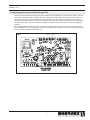
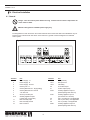
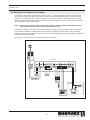
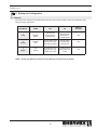
Installation & Operating Manual
3916067 01.13
ADC100 Draft Control
USA
CAN
Product Information .......................... Chapter 1+2
Mechanical Installation ......................... Chapter 3
Electrical Installation ............................. Chapter 4
Start Up and Configuration .................. Chapter 5
Maintenance and Troubleshooting ...... Chapter 6
Job Name:
Installer:
Installation Date:
READ AND SAVE THESE INSTRUCTIONS!
ENERVEX Inc.
1685 Bluegrass Lakes Pkwy.
Alpharetta, GA 30004
P: 770.587.3238
F: 770.587.4731
T: 800.255.2923
[email protected]
www.chimneyfans.com
3916067 01.13
1. Product Information
1.1Function................................................................................................3
1.2Shipping................................................................................................3
1.3Warranty................................................................................................3
2. Specifications
2.1 Dimensions & Capacities.......................................................................4
3. Mechanical Installation
3.1Location.................................................................................................5
3.2 Mounting the Control Unit.....................................................................5
3.3 Connection of the Proven Draft Switch..................................................6
3.4 Installation of the Chimney Probe..........................................................6
3.5 Adjusting the Fan Speed and Post Purge Time.....................................7
4. Electrical Installation
4.1General.................................................................................................8
4.2 Connection Diagram.............................................................................9
4.3 Wiring of a Gas Fireplace....................................................................10
4.4 Wiring of a Gas Fireplace With a Damper........................................... 11
4.5 Wiring of 3-Phase Fan........................................................................12
5. Startup and Configuration
5.1General...............................................................................................13
5.2 Sequence of Operation.......................................................................14
5.3 Operating Pressure.............................................................................15
6. Maintenance and Troubleshooting
............................................................................................................15
Symbol Legend:
The following terms are used throughout this manual to bring attention
to the presence of potential hazards or to important information
concerning the product.
Caution: Indicates an imminent hazardous situation
which, if not avoided, may result in personal injury or
property damage.
Danger: Indicates an imminent hazardous situation
which, if not avoided, will result in death, serious injury or
substantial property damage.
TO REDUCE THE RISK OF FIRE, ELECTRICAL SHOCK OR INJURY TO PERSONS,
OBSERVE THE FOLLOWING:
How to use this manual
1. Use this unit in the manner intended by the manufacturer. If you have questions, contact the manufacturer at the address or telephone number listed on the front of the manual.
2. Before servicing or cleaning the unit, switch off at service panel and lock service panel to prevent power from being switched on accidentally.
3. Installation work and electrical wiring must be done by a qualified person(s) in accordance with applicable codes and standards.
4. Follow the appliance manufacturer’s guidelines and safety standards such as those published by the National Fire Protection Association (NFPA), and the American Society for Heating, Refrigeration and Air Conditioning Engineers (ASHRAE), and the local code authorities.
5. This unit must be grounded.
This installation manual does not contain any system design
documentation. System design documentation is available from any
authorized ENERVEX representative.
Accessories, fans and variable frequency drives are not covered by
this manual. Please refer to these component’s individual manuals.
2
3916067 01.13
1. Product Information
1.1 Function
Use
The ENERVEX ADC100 Draft Control is a fan speed and appliance control used to control draft for a gas appliance such as a fireplace, stove or furnace. It may be interlocked with the appliance and is for use in systems where modulation is not required. It controls the speed of a fan to maintain proper draft and
pressure in a chimney system. The ADC100 is for use with ENERVEX model RS or GSV fans and is a component in the residential EcoDamper..
Function
The ADC100 control comes with the PDS1.
The PDS is a required safety function used to ensure a negative pressure is maintained in the chimney. It also prevents appliance operation during an electrical or mechanical failure in the system. The ADC100 can operate the chimney fan in manual or automatic mode. Manual mode allows the user to adjust the speed of the fan at any time using the potentiometer on the board. In Automatic Mode, the ADC100 will ignore the potentiometer and ramp the fan up until the PDS closes. If the PDS opens, the control will ramp up the fan until there is enough draft to re-close the switch.
The ADC100 can be interlocked with up to two appliances. Connections are made at the Auxiliary In and Auxiliary Out terminals. A 24VDC out connection is available. When an appliance is interlocked to the control, a post-purge function becomes available. The post purge keeps the fan running for a set time after the last appliance shuts down to evacuate any remaining flue gases. The post purge time on the ADC100 is adjustable from 0-3 minutes via a potentiometer on the control board.
Construction
The housing is NEMA 1 rated ABS plastic.
Code Compliance
System installation must conform to the requirements of the authority having jurisdiction. When required by the authority having jurisdiction, the installation must also conform to the NFPA31, NFPA54 or NFPA211.
The damper relay allows a damper actuator to be interlocked directly to the control. The control ensures that the damper is open before releasing the appliance for operation. If at any point the control has sensed total failure, the ADC100 will go into an alarm for 30 seconds and will attempt a retry. In the event of a mechanical or electrical failure, the damper fails to the open position.
All electrical wiring must be in accordance with the requirements of the authority having jurisdiction or, in absence of such requirements, with the National Electric Code, NFPA 70.
1.2 Shipping
ADC100 includes the control unit, PDS1, stack probe and silicone tubing.
* If other components are shipped, they will appear as separate items on the packing list.
1.3 Warranty
2-Year Factory Warranty. Complete warranty conditions are available from ENERVEX, Inc.
3
3916067 01.13
2. Specifications
2.1 Dimensions & Capacities
ADC100 Control
Power supply
Amperage
Operating temperature
Control signal
Control relay
Output
Post Purge Time
Alarm Delay Time
Dimensions
Weight
Chimney Probe
Dimensions
C
V
A
°F/°C
mA
A in/mm
B in/mm
C in/mm
lbs/kg
1x120VAC
6.3
-4 to 122 / -20 to 50
max. 10
Max. 120 VAC / 8A
10-120
0-10
0-3 Minutes
15 Seconds
9.6 / 244
6.3 / 160
3.5 / 90
2.6 / 1.2
D in/mm
E in/mm
4.25 / 108
3.50 / 89
VAC
VDC
ADC100
B
A
E
D
ADC100
4
3916067 01.13
3. Mechanical Installation
3.1 Location
The ADC100 Control Unit must be installed indoors.
As shown in the diagram below, the control will be wired directly to a 120/1/60 VAC power supply. The control will also be connected to the fan, appliance and damper (if used). For detailed wiring information, see Chapter 4.
ADC100
Fig. 1
ADC100
ADC100
DAMPER
(SOLD
SEPARATELY)
ENERVEX
PDS1
ENERVEX
3.2 Mounting the Control Unit
The ADC100 control may be mounted directly to a wall. To mount, remove the cover and locate the (4) mounting holes. Using the hole-pattern shown below, mount the control using #6 screws. Once it is attached, wire the unit in accordance with Chapter 4.
Fig. 2
8.9 in
(227 mm)
4 MOUNTING HOLES
5.0 in
(127 mm)
5
3916067 01.13
3.3 Connection of the Proven Draft Switch and Stack Probe
The Proven Draft Switch (PDS) must be installed indoors, in the vertical position (pre-drilled knockouts face down). Mount the control upright to a wall or other flat surface. Do NOT lay the control down or mount horizontally.
A Proven Draft Switch (PDS) must be used with the ADC100 control as a system safety device. The PDS monitors the pressure inside the stack and signals the control to shut down the appliance if insufficient draft exists. A stack probe senses the pressure read by the PDS and is connected via silicone tubing.
The silicone tubing supplied with the PDS should be connected to the NEGATIVE (-) port of the PDS. This is the bottom port on the switch. The standard tube length is 6 feet. The distance can be extended up to 25 feet by using 1/4” rigid plastic or copper tubing as temperature allows (not supplied).
Fig. 3
C
NC
NO
+
-
NEGATIVE PRESSURE PORT
3.4 Installation of the Chimney Probe
The probe must be installed between the appliance and the exhaust fan. If a damper is used in the system, the probe should be installed between the appliance and damper.
Locate the probe at least a distance three (3) vent diameters away from any elbow, tee or damper. For fireplace installations, the probe should be installed close to the fan inlet. See Fig. 5.
To produce an accurate pressure reading, the probe should be installed flush with the inner wall of the chimney or stack. If double walled stack is used, the probe should be flush with the inner most wall.
Fig. 4
DAMPER
CHIMNEY
PROBE
6
CHIMNEY
PROBE
3916067 01.13
3.5 Adjusting the Fan Speed and Post Purge Time
There are two potentiometers located on the main control board of the ADC100. To increase the fan speed, rotate the potentiometer labeled Fan Spd clockwise. Alternately, rotating the potentiometer counterclockwise will decrease the fan speed. In Manual mode, the potentiometer can be adjusted at any time during normal operation to increase or decrease the fan speed. When the control is in Automatic mode, the potentiometer is only used to set the initial speed of the fan. After that, the control will automatically adjust the fan speed to ensure the PDS stays closed during appliance operation.
A second potentiometer, labeled PG Time, is located on the bottom right corner of the control board. The post purge time is adjustable from 0 (no post purge) to 3 minutes. Turning the knob clockwise increases the post purge time while turning it counter-clockwise decreases the time.
Fig. 5
Purge Time Fan Speed
7
3916067 01.13
4. Electrical Installation
4.1 General
Danger: Turn off electrical power before servicing. Contact with live electric components can
cause shock or death.
ADC100 is designed for 1x120VAC power supply only.
The designations for each terminal on the control board are shown below. Note that some installations may not require the use of all terminals. Also shown in this section is a general connection diagram for an ADC100 control system.
Fig. 6
XTP
26 27 28
+24V 0-10 GND
Terminal
Use Terminal
1 Power Supply - L1
14-15
2 Power Supply - N
16-17
3 Power Supply - Ground
18-19
4 Chimney Fan- L1
20
5 Chimney/Exhaust Fan - N (regulating)
21
6 Chimney/Exhaust Fan- Ground
22-23
7 + 24 VDC Out
8 Ground (-24 VDC) Out
24-25
9-10 Auxiliary Appliance Input 1
(10-240 VAC or 5-30 VDC)
26
11 PDS- Normally Open
27
12 PDS- Normally Closed
28
13 PDS- Common
29-30
8
Use
Damper Relay
Damper Prove
VFD Relay
0-10 VDC Output
0 VDC Output (Gnd)
Auxiliary Appliance Output 1
(Max Amperage 250 VAC 8 A)
Auxiliary Appliance Input 2
(10-240 VAC or 5-30 VDC)
XTP- +24 VDC Out - Not Applicable
XTP In (0-10 VDC) - Not Applicable
XTP In (0 VDC) - Not Applicable
Auxiliary Appliance Output 2
(Max Amperage 250 VAC 8 A)
3916067 01.13
4.2 Connection Diagram
The connection diagram shown in Fig. 7 below shows typical connections for a single phase fan. If a 3-phase fan is used, a VFD must be connected between the fan and control.
Fig. 7
ADC 100
ENERVEX
To Fireplace
9
3916067 01.13
4.3 Wiring of a Gas Fireplace
To interlock the ADC100 with a gas fireplace as shown in Fig. 8, connect the Auxiliary In terminals 9 and 10 on the control board to a wall switch. Either by using line voltage or use board voltage from terminals 7 and 8 as depicted in figure 8. Connect the gas valve or ignition to Auxiliary Out at terminals 22 and 23. The Auxiliary Out is a normally open dry contact that closes when the PDS closes and releases the fireplace for operation. The Auxiliary In terminals are rated for maximum 250/125 VAC/VDC. Place a jumper between terminals 16 and 17 if the damper is not used.
Note: See Fig. 10 in Section 4.5 for connection of 3-phase fan with VFD.
Fig. 8
ADC 100
XTP
26 27 28
10
3916067 01.13
4.4 Wiring of a Gas Fireplace with a Damper
To interlock the ADC100 with a gas fireplace as shown in Fig. 9, connect the Auxiliary In terminals 9 and 10 on the control board to a wall switch. Either by using line voltage or use board voltage from terminals 7 and 8 as depicted in figure 8. Connect the gas valve or ignition to Auxiliary Out at terminals 22 and 23. The Auxiliary Out is a normally open dry contact that closes when the PDS closes and releases the fireplace for operation. The Auxiliary In terminals are rated for maximum 250/125 VAC/VDC.
NOTE: If an electronic ignition control is used with the fireplace, do NOT interlock it with damper actuator. Damper actuator should interlock with the ADC100 control only.
To interlock the damper to the control, connect the actuator to terminals 14 and 15 as shown in Fig. 9. The actuator must include an endswitch to enable the damper prove function. The damper prove function is a dry contact that closes when the damper proves open. Connect the Common and Normally Open terminals of the actuator endswitch to terminals 16 and 17 on the board.
Note: See Fig. 10 in Section 4.5 for connection of 3-phase fan with VFD.
Fig. 9
ADC 100
XTP
26 27 28
11
3916067 01.13
4.5 Wiring a 3-Phase Fan
Connect a 3-phase fan to the control system via a variable frequency drive (VFD). The VFD receives external 3-phase power (208-230 or 400-480 VAC). A 0-10 VDC signal from the ADC100 is converted to a 0-60 Hz signal from the VFD to modulate the fan speed. Any appliance(s) or damper should be connected as shown in Fig 8 and 9.
Fig. 10
ADC 100
XTP
26 27 28
12
3916067 01.13
5. Startup and Configuration
5.1 General
Dip switches are located on the control board to allow the user to specify certain functions of the ADC100. Verify settings using the table below.
ON
DEFAULT
POSITION
DIP SWITCH
NAME
OFF
1
(Left)
MANUAL
RESET
Automatic reset
at power failure or
insufficient draft
2
(Center)
MANUAL
ADJ
Automatic Mode-control
speeds up fan if PDS
opens during operation
Manually adjust
fan speed using
potentiometer
OFF
3
(Right)
PDS
CHECK*
No monitoring to see
if the PDS was in NC
position prior to start
The PDS must be
in NC position prior
to start
ON
Manual reset at
power failure or
insufficient draft
NOTE: Do NOT turn PDS check off unless requested by the factory technical support.
13
OFF
3916067 01.13
5.2 Sequence of Operation
The sequence of operation flow chart is shown in figure 11 below.
Fig. 11
De- Energize
All for Retry
Idle State
Maintain Flashing State
for 30 seconds
Aux In Enabled
One Flash
Alarm
Taking longer than
90 seconds
Open Damper
Damper Open Proof
Two Flash
Alarm
Initial PDS Proof
Taking longer than
180 seconds
VFD and Fan
Enabled
Initial PDS Proof
Three Flash
Alarm
Loss of PDS Proof
for 15 seconds
Four Flash
Alarm
Loss of Damper Open Proof
Aux Out
Enabled
PDS Proof
Aux Out
Disabled
Alarm Stages
Flashes 1 - if damperprove does not close 90 seconds after auxin, go into alarm for 30 seconds, followed by a full retry
Flashes 2 - if initial pdsprove does not close 180 seconds after damperprove, go into alarm for 30 seconds, followed by a full retry
Flashes 3 - if pds loses proof for 15 seconds after initial pdsprove, auxouts de-energize, stay in alarm until pdsprove returns and auxout will re-energize
Flashes 4 - if at any point after auxout proves the damperprove is removed, the board immedialy goes into alarm for 30 seconds, followed by a full retry
Flashes 5 - *must have sw3 on* if pds is proved prior to auxin, board will go into alarm and no further states can be achieved until proof is removed
Start
1. A call for heat from the appliance energizes the ADC100 inputs at terminals 9 and 10.
Sequence 2. If a damper is connected, it begins to open. Once open, the damper prove contact closes (Terminals 16 and 17).
3. The ADC100 begins to ramp up the fan.
4. The Proven Draft Switch closes when adequate draft is achieved and ADC100 adjusts fan to speed setting on the potentiometer.
5. The ADC100 control releases the appliance for operation by closing dry contact between terminals 22 and 23 (and terminals 29 and 30).
Operating
Sequence
Manual Mode:
1. Fan runs at a constant speed and can be adjusted during normal operation using the potentiometer.
2. If the Proven Draft Switch opens, a 15 second timing cycle starts.
3. If the Proven Draft Switch has not been made within 15 seconds, the auxiliary out contact opens and an alarm condition exists.
4. If the Proven Draft Switch closes, the control automatically resumes normal operation at set speed.
14
3916067 01.13
Automatic Mode:
1. Fan runs at speed setting of the potentiometer but cannot be adjusted using the potentiometer during operation.
2. If the Proven Draft Switch opens, the fan begins to ramp up.
3. If PDS closes, fan speed remains at that speed.
4. If the PDS has not closed by the time the fan has ramped up to 100% speed, a 10 second timing cycle begins.
5. If PDS does not close within 15 seconds the auxiliary out contact opens and an alarm condition exists.
6. If the Proven Draft Switch closes while the control is in alarm, the fan will resume the original speed setting.
Shutdown
Sequence
1. The call for heat signal from the appliance is turned off.
2. Fan output continues at pre-set speed for the set post purge time (0-3 minutes).
3. Fan output is set to zero.
5.3 Operating Pressure
The operating pressure of the ADC100 Control is determined by the PDS switch. The PDS-1 used with the ADC100 has a pressure setting of 0.05” W.C. +/- 0.03” W.C. As long as the pressure is within this range, the fireplace and/ or appliance will continue to operate. Should the pressure fall outside of this range, it may be necessary to adjust the fan speed. The user may use a manometer or other device to read the pressure inside the stack.
For fireplaces, a standard smoke/ flame test should be performed before normal operation (specified in appliance manual). This test will determine if the fan is running at the correct speed.
6. Maintenance and Troubleshooting
Observation
Problem
Solution
Heating appliance/
fireplace cycle on and off
- Potentiometer setting is too low
- Turn potentiometer clockwise to increase fan speed.
Fan is ‘hunting’
(increasing speed and
then decreasing speed
constantly)
- Fan speed control is set too low.
- Increase potentiometer setting.
Fan will not come on
- ADC100 is not wired correctly
- Draft in chimney fluctuates.
- There may be sufficient natural
draft
- Fan is not working
Heating appliance or
fireplace will not come
on
- Fan is not working
- No power to the ADC100
- Proven draft switch is not
properly connected to the
chimney.
- PDS is not working
- Move Stack Probe closer to fan.
- Check wiring and correct
- If the PDS is closed when the start signal is applied,
sufficient natural draft exists for the fan to run. The
ADC100 can run the fan even during these conditions if
dipswitch #1 is set to the ON position to initialize a PDS
check during the start up sequence.
- Check the fan and if necessary, repair or replace. Verify
all wiring to fan and control is correct and control is
receiving external power.
- Check the fan and if necessary, repair or replace. Verify
all wiring to fan and control is correct and control is
receiving external power.
- Make sure the probe is properly inserted into the stack,
so the tip of the probe is flush with the inside of the
chimney.
- Replace relay or switch
Heating appliance/
fireplace will not shut off
- ADC100 is not wired correctly
- Check wiring and correct.
15
3916067 01.13
ENERVEX Inc.
1685 Bluegrass Lakes Pkwy.
Alpharetta, GA 30004
P: 770.587.3238
F: 770.587.4731
T: 800.255.2923
[email protected]
www.enervex.com