1
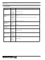
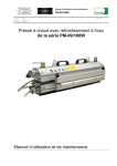
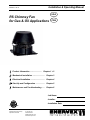
Installation & Operating Manual 3000270 05.12 RS Chimney Fan for Gas & Oil Applications USA CAN Product Information ........................ Chapter 1 + 2 Mechanical Installation ......................... Chapter 3 Electrical Installation ............................. Chapter 4 Start Up and Configuration .................. Chapter 5 Maintenance and Troubleshooting ...... Chapter 6 Job Name: Installer: ERTEK INT Installation Date: CM C LISTED US ENERVEX Inc. 1685 Bluegrass Lakes Pkwy. Alpharetta, GA 30004 P: 770.587.3238 F: 770.587.4731 T: 800.255.2923 [email protected] www.chimneyfans.com 3000270 05.12 1. Product Information 1.1Function................................................................................................3 1.2Shipping................................................................................................3 1.3Warranty................................................................................................3 2. Specifications 2.1 Dimensions and Capacities...................................................................4 2.2 Planning Ahead.....................................................................................5 3. Mechanical Installation 3.1 Transport Safety Device........................................................................6 3.2 Single Fan on Steel Chimney................................................................6 3.3 Single Fan on Brick Chimney................................................................7 3.4 Multiple Fans on Steel Chimney............................................................8 3.5 Multiple Fans on Brick Chimney - Oversized Flue................................8 3.6 Installation for High Temperatures.........................................................8 3.7 Wall Mounting of Chimney Fan..............................................................9 3.8 Installation of Proven Draft Switch (PDS)..............................................9 4. Electrical Installation 4.1General...............................................................................................10 4.2 Wiring Diagram for Single Fan with FSC............................................10 4.3 Wiring Diagram for Two Fans with FSC.............................................. 11 4.4 Wiring Diagram for Single Fan with ADC 100..................................... 11 5. Start-Up and Configuration 5.1 System Testing....................................................................................12 5.2 Adjusting the Chimney Fan Speed......................................................12 5.3 Adjusting the Proven Draft Switch Setting..........................................12 6. Maintenance & Troubleshooting 6.1 Prior to Cleaning.................................................................................13 6.2 Care and Cleaning..............................................................................13 6.3 Chimney Cleaning Intervals ...............................................................13 6.4 Troubleshooting..................................................................................14 Symbol Legend: The following terms are used throughout this manual to bring attention to the presence of potential hazards or to important information concerning the product. Danger: Indicates an imminent hazardous situation which, if not avoided, will result in death, serious injury or substantial property damage. ! ! TO REDUCE THE RISK OF FIRE, ELECTRICAL SHOCK OR INJURY TO PERSONS, OBSERVE THE FOLLOWING: Caution: Indicates an imminent hazardous situation which, if not avoided, may result in personal injury or property damage. How to use this manual 1. Use this unit in the manner intended by the manufacturer. If you have questions, contact the manufacturer at the address or telephone number listed on the front of the manual. 2. Before servicing or cleaning the unit, switch off at service panel and lock service panel to prevent power from being switched on accidentally. 3. Installation work and electrical wiring must be done by a qualified person(s) in accordance with applicable codes and standards. 4. Follow the appliance manufacturer’s guidelines and safety standards such as those published by the National Fire Protection Associations (NFPA), and the American Society for Heating, Refrigeration and Air Conditioning Engineers (ASHRAE), and the local code authorities. 5. This unit must be grounded. This installation manual does not contain any system design documentation. System design documentation is available from any authorized ENERVEX representative. Accessories and controls are not covered by this manual. Please refer to these component’s individual manuals. 2 3000270 05.12 1. Product Information 1.1 Function Use The RS Chimney Fan is a chimney top mounted ventilator that is designed to provide large flue gas volume capacities. It is designed and intended for use with residential gas or oil fired central space heating systems, for volume water heating or for combination space heating/volume water heating. It is also suitable for use with gas-fired fireplaces, stoves, BBQ’s or residential pizza ovens. This product is developed to prevent draft problems from occurring by creating a mechanical draft in venting systems and thereby also increasing the capacity and efficiency of a venting system. The use of the RS Chimney Fan is not restricted to any type of chimney, because the fan creates a negative pressure (below atmospheric) in the chimney or vent. Code Compliance Installations must conform to requirements of the authority having jurisdiction. Where required by the authority having jurisdiction, the installation must also conform to the Standard for Draft Equipment and The National Fuel Gas Code, ANSI Z223.1/NFPA 54. All electrical wiring must be in accordance with the requirements of authority having jurisdiction or, in the absence of such requirements, with the National Electrical Code, NFPA70. Listing The Model RS is tested and listed to UL Standard 378, Standard for Draft Equipment. The fan is manufactured at an ISO9001 certified plant and bears the European CE compliance label. The chimney fan must be interlocked with the connected appliance(s) to insure proper combustions and to avoid flue gas spillage. 1.2 Shipping The packing list (attached to one of the packages) clearly lists all items in the shipment and each package has a label showing the contents. Check the list against all materials on the job site for completeness. NOTE: All single phase fans are shipped with a capacitor and junction box connected via conduit. The capacitor is located INSIDE the junction box. Please do not discard. 1.3 Warranty ENERVEX products are warranted for a period of two (2) years following the date of invoice. Replacement or repair will be at ENERVEX’s discretion, provided factory inspection shows a defect in material or workmanship. Complete warranty conditions are available from ENERVEX. 3 3000270 05.12 2. Specifications 2.1 Dimensions & Capacities Model RS 009 RS 012 Discharge RS 014 RS 016 Horizontal Fan Type Axial Vane Motor Type Totally enclosed, Variable speed, Class H Voltage V AC 1x120 RPM 1600 CFM 0.0 Ps 450 950 1400 1950 Amperage Amps 0.5 1.2 1.4 3.9 Motor Output Weight Dimensions A BxB C D E Temperature Rating HP 1/30 1/10 1/7 1/3 kW 0.025 0.08 0.1 0.25 lbs 29 37 47 61 kg 13 17 21 28 in 10.2 11.5 13.1 16.0 mm 259 292 334 407 in 11.7 14.3 16.6 18.8 mm 296 364 422 478 in 10.8 13.5 15.5 17.4 mm 275 344 395 441 in 3.0 3.3 3.9 3.9 mm 75 85 100 100 in 9.4 11.6 13.5 15.4 mm 238 294 342 391 Interm. 575°F/300°C Cont. 482°F/250°C 1 Junction Box 2Conduit/cord 3Motor 4 Motor Housing 5 Cooling Plates 6 Bird Screen 7 Base Plate 8 Locking Nut 9Inlet 10 Axial Vane 11Hinges 12Capacitor (inside junction box) Capacity Sound Data Model Lw dB (measured in accordance with ISO 3744) Lp dB(A) 125Hz 250Hz 500Hz 1000Hz 2000Hz 4000Hz 8000Hz RS 009 54 50 47 43 38 31 25 21 RS 012 64 60 55 52 48 42 34 30 RS 014 75 69 65 62 57 51 44 41 RS 016 81 76 72 69 64 58 52 47 4 3000270 05.12 2.2 Planning Ahead ! 1. Observe proper combustion air requirements. 2. Provide a firm support system for the chimney fan. 3. Determine the type of system involved. 4. Observe proper safety measures are taken to assure safe use of the wood burning appliances Combustion Air Requirements: Provisions for combustion air must be in accordance with applicable local codes. If the heating system is installed in an unconfied space, adequate air vill be available via normal infiltration. If the heating system in installed in a confined space, (a space with a volume less than 50 cubic feet per 1,000 Btu/hr of input for all fuel burning equipment) or building construction is unusually tight, adequate air for combustion must be provided by two openings: one located about 6” below the ceiling, the other about 6” above the floor. Each opening must have a minimum free area as follows: 1. One square inch per 4,000 Btu/hr of input when communicating directly with the outside or through a vertical duct. 2. On square inch per 2,000 Btu/hr when communication through horizontal ducts to the outisde. 3. One square inch per 1,000 Btu/hr when ventilation air is provided by openings in doors, etc. to adjoining spaces having adequate infiltration. Support system for the chimney fan: Prior to installation of the chimney fan, it must be assured the chimney can safely carry the weight of the chimney fan. A steel chimney should be well supported at the roof penetration point. If the chimney extends more than 20’ above the roof, the chimney and the fan should be secured by wires attached on the chimney and on the roof at 2 to 3 different points. Brick chimneys usually do not need any kind of support to carry the weight of the chimney fan. System Type Direct connect oil or gas appliances (no draft hood) normally do not require any mechanical draft adjustment. However, if there are long horizontal breechings and far between the appliances, it is a good idea to install mechanical vent dampers, so adjustments of the draft can be easily made. Draft hood systems could generally speaking have vent dampers installed. The vent dampers are used to balance the system and assure that only a minimum of dilution air is pulled through the draft hoods. Safety Devices Local codes usually require installation of safety devices, when mechanical draft is provided in an oil or gas fueled system. Make sure a differential pressure switch (proven draft switch) is installed to assure that no appliance will fire unless there is a proven draft. ! Adequate fresh air must be provided for combustion; otherwise, improper operation and inadequate venting of deadly flue gases may result. 5 3000270 05.12 3. Mechanical Installation 3.1 Transport Safety Device If a transport safety device is present, remove it from the vane and make sure that the vane can revolve without hindrance. RS 14/16: Before mounting, the transport safety device on the hinges must be removed. 3.2 Single Fan on Steel Chimney Step 1: Prepare fan location If a stack cap is already installed, it must be removed. The steel chimney adapter (SCA) slides right into the chimney, where the long collar engagement ensures safe anchoring. If necessary, the adapter can be secured by means of long self-tapping stainless steel screws into the side of the collar through the chimney wall. ! If the steel chimney is air cooled, a special adapter for such chimney must be used. Measure the inside diameter of the flue and cut a corresponding hole in the center of the fiber mat. If the flue is so big that the throat in the adapter has been reduced to fit the throat of the fan, the hole in the fiber mat should correspond to the throat. The aluminum foil on the fiber mat must face upward (against fan base). Step 2: Preparation of fan Locate the installation brackets in the grooves on the underside of the fan base, using the bolts and nuts supplied to secure the brackets. Note that the bolts shall be installed from the bottom side in the two inner holes. Adjust the final position of the installation brackets ensuring that there is a small gap between the brackets and the flue wall/adapter throat. Tighten the nuts. If the brackets touch the flue wall, it may create some vibration noise. Step 3: Attaching the fan The chimney fan is now ready for installation on the top of the chimney. Place the fiber mat with the aluminum foil facing upwards on the top of the adapter, and place the fan on top of the mat. High temperature silicone can be applied on the side of the mat, but is not required. It can also be painted. It is not necessary to bolt the fan to the chimney. ! Caution: Under conditions with extremely strong winds surrounding the top of the chimney, the chimney fan must be secured by steel wires supplied with the fan. 6 3000270 05.12 3.3 Single Fan on Brick Chimney Step 1: Prepare fan location The installation procedure is the same whether the flue is round or square. If a clay tile flue liner is installed, it might stick up a few inches. Cut it back so it is flush with or no more than 1/2 inch above the chimney crown. Measure the inside diameter of the flue, cut a corresponding hole in the fiber mat leaving a minimum distance of 3/4” to any side of the fiber mat. The aluminum foil on the fiber mat must face upwards (against fan base). Step 2: Preparation of fan Locate the installation brackets in the grooves on the underside of the fan base using the bolts and nuts supplied to secure the brackets. Note that the bolts shall be installed from the bottom side in the two inner holes. Adjust the final position of the brackets ensuring that there is clearance between the brackets and the flue wall. If the brackets touch the wall, it may generate some vibration noise. Step 3: Attaching the fan The chimney fan is now ready for installation on the top of the chimney. Place fiber mat with the aluminum foil facing upwards on the top of the chimney, and place the fan on top of the mat. High temperature silicone can be applied on the side of the mat, but is not required. It can also be painted. It is not necessary to bolt the fan to the chimney. ! Caution: Under conditions with extremely strong winds surrounding the top of the chimney, the chimney fan must be secured by steel wires supplied with the fan. 7 3000270 05.12 3.4 Multiple Fans on Steel Chimney If two or more chimney fans are required to create sufficient draft, installation procedures are the same as for single fan installation on a steel chimney. The only difference is that the fans are sitting next to each other on the top of the chimney. A special adapter plate is required. When installing multiple fans, it is extremely important that the fans are of the same model and size, and they must be controlled in tandem by one (1) motor speed control. 3.5 Multiple Fans on a Brick Chimney - Oversized Flue If two or more fans are required to create sufficient draft, a special adapter plate is required. The adapter plate should be made of stainless steel (14 GA or thicker), depending on the size and the fan models used. The two holes in the plate should match the throat diameter of the fan model used and the distance from center to center should be at least equal to the fan width (dimension “B” in 1.5. Dimensional Data). The adapter should be sealed with silicone and bolted onto the top. When installing multiple fans, it is extremely important that the fans are of the same model and size, and they must be controlled in tandem by one (1) motor speed control. A similar approach should be taken if the flue size exceeds the fan base dimensions. The adapter plate should be sized so it covers the flue and secured. A hole should be cut in the center of the plate and the fan mounted centered over the hole. 3.6 Installation for High Temperatures If the fan is used for applications where the flue gas temperatures exceed 400°F at the flue exit, and does not exceed 650°F, dilution bolts must be used. Dilution bolts will cause cool air to dilute the warm flue gas, by lifting the fan and leaving space so the cool air can get in under the fan base. The dilution bolts should be installed in the outer holes in the fan base. The dilution bolts are adjustable and should be adjusted so the flue gas temperature does not exceed 400°F when discharged through the fan. When using dilution bolts the fan’s actual capacity is reduced and a stronger model may be required. The fiber mat is not required when using dilution bolts. 8 3000270 05.12 3.7 Wall Mounting of Chimney Fan When mounting the chimney fan on a wall, the installation instructions for installation on a steel chimney should be followed. Use of the adapter SCA can make the installation easier, but is not a requirement. To ease installation, detach the fan base by removing the bolts holding the hinges together. Center the fan base over the outlet and bolt the base onto the wall with the hinges pointing upwards. After mounting the base securely, attach the fan motor housing by reassembling the fan hinges. Seal with silicone all around the fiber mat to prevent rain from entering the flue. Bolt Bolt 3.8 Installation of Proven Draft Switch (PDS) A safety system must be interlocked with the appliance(s). The safety system could utilize a Proven Draft Switch, a thermal switch or a flow switch. The device must be interlocked with the heating appliance so it shuts down in case of insufficient draft, fan failure or power failure. Please refer to the PDS Installation Manual if this control is used. For more information on alternative safety systems, please contact ENERVEX, Inc. The figure shows the location of the probe for the PDS. Location is important to make sure there is enough pressure or draft available for the switch to work. ! A safety device that prevents the heating appliance operation, in case of a power failure or inadequate draft situation, must be installed. 9 3000270 05.12 4.Electrical Installation 4.1 General Danger: Turn off electrical power before servicing. Contact with live electric components can cause shock or death. All electrical wiring must be in accordance with requirements of authority having jurisdiction or, in absence of such requirements, with National Electrical Code NFPA 70 — latest edition. If an external electrical source is utilized, system must be electrically grounded in accordance with requirements of the authority having jurisdiction or, in the absence of such requirements, with the National Electrical Code NFPA 70 — latest edition. RS 9 RS 12 RS 14 RS 16 Power requirements for the system depends on the fan size. Electrical requirements are: 1 x 120 V/60Hz 1 x 120 V/60Hz 1 x 120 V/60Hz 1 x 120 V/60Hz 0.4 Amps 1.2 Amps 1.4 Amps 3.9 Amps The chimney fans have a split capacitor motor with infinitely variable speed. The fan speed control supplied is rated 1x120V/60 Hz and 5 Amps. It has an adjustable low voltage set point of min. 65 V +/- 5 V. Notice: If any of the original wire supplied with the system must be replaced, use similar wire of the same temperature rating. Otherwise, insulation may melt or degrade, exposing bare wire. 4.2 Wiring Diagram for Single Fan with Fan Speed Control The wiring diagram below shows the wiring of the chimney fan and how it is connected to the fan speed control. COM TR GREEN BLACK RED WHITE 24 VAC WEATHERPROOF BOX FAN MOTOR ORANGE PROVEN DRAFT SWITCH HOT TH 24V GAS VALVE N 120/1/60 L NOTES: 1 FAN SPEED CONTROL All wiring must be in flexible or rigid metal conduit THE DISCONNECT MEANS AND CIRCUIT PROTECTION ARE TO BE PROVIDED BY THE INSTALLER OF THIS DEVICE LEGEND: 24 VAC 120 VAC 10 3000270 05.12 4.3 Wiring Diagram for Two Fans with Fan Speed Control The diagram below shows the wiring of two chimney fans and how they are connected to the fan speed control. PROVEN DRAFT SWITCH 24 VAC GREEN BLACK WEATHERPROOF BOX WHITE ORANGE FAN MOTOR RED GREEN BLACK WEATHERPROOF BOX 24V GAS VALVE WHITE ORANGE HOT TH RED COM TR FAN MOTOR N 120/1/60 L FAN SPEED CONTROL NOTES: WEATHERPROOF BOX All wiring must be in flexible or rigid metal conduit 1 THE DISCONNECT MEANS AND CIRCUIT PROTECTION ARE TO 2 BE PROVIDED BY THE INSTALLER OF THIS DEVICE LEGEND: 24 VAc 120 VAC 4.4 Wiring Diagram for Single Fan with ADC 100 The diagram below shows the wiring of a single chimney fan when used in conjunction with an ADC 100-P or ADC 100-E Control. ADC 100 24 VAC COM TR HOT TH 24V GAS VALVE OR IGNITION 11 3000270 05.12 5. Start-Up and Configuration 5.1 System testing Before any adjustments are made to the system, follow these procedures: 1. Turn the chimney fan ON and make sure that it is operating. Increase and decrease the speed of the fan by adjusting the fan speed control to make sure it is operating properly. 2. Turn the fan OFF and make sure the pressure switch opens, so the power to the circuit, it controls, is disconnected. Danger: Check other heating appliances (water heater, furnace, fireplace etc.) for proper operation while the chimney fan is operating. Make sure no flue gases are spilling out as this can lead to carbon monoxide poisoning. 5.2 Adjusting the Chimney Fan Speed Start up all appliances. Use the fan speed control to set the speed of the chimney fan so no back pressure is experienced anywhere in the system. Check the system for flue gas spillage. Mark this setting on the fan speed control cover. 5.3 Adjusting the Proven Draft Switch Setting Remove the snap-on cover from the conduit enclosure by loosening its retaining screw. Turn the slotted Adjustment Screw clockwise to raise the set point pressure and counter clockwise to lower the set point. Set the adjustment to its lowest position. With all appliances operating, reduce the speed of the fan to the set point, where the appliance(s) starts to spill flue gas. Increase the speed of the fan gradually to the point where there is no more spillage. Raise the switch’s set point so it opens. Return the fan speed to the original setting marked on the cover. The system is now adjusted so the flue gas spillage will disconnect the heating appliance(s). The procedure described here may not cover all Proven Draft Switches, so please review the Installation Manual for the switch being used. 12 3000270 05.12 6. Maintenance & Troubleshooting 6.1 Prior to Cleaning Remove butterfly nut or screw from each hinge prior to cleaning. Remove Butterfly Nut or Screw from each Hinge 6.2 Care and cleaning The Chimney Fan System is designed for prolonged use. The fan should be inspected at least once a year when the chimney is inspected. Fuel residues and other deposits should be removed from the fan blades and the bottom of the motor housing. The top of the fan is hinged and can be opened in order to ease the cleaning. ! Warning: Do not open the motor housing unless power to the chimney fan has been disconnected. 6.3 Chimney cleaning intervals It is extremely important to keep the chimney flue clean from products of combustion and deposits. Unburned oil residues can cause a chimney fires. Cleaning intervals depend on the use of the appliance. The more the appliance is used, the more often the chimney flue needs cleaning. As there are no firm guidelines for cleaning intervals, have the chimney inspected on a regular basis (every quarter or so) to determine what the interval should be. Then follow this interval. No matter how much used, a chimney flue should be cleaned and inspected at least once every year. NOTE: The chimney should be cleaned by a trained professional. We recommend using a “Certifed Chimney Sweep” certified by Chimney Safety Institute of American. You can find a Certified Chimney Sweep at www.csia.org or www.ncsg.org or by calling (317) 837-5362 or (317) 837-1500. 13 3000270 05.12 6.4 Troubleshooting Observation Problem Solution There is no power going to the fan - The circuit breaker may be off - Fan speed control is off - Bad electrical connections - Check the circuit breaker - Bad electrical connections - The fan speed control’s low voltage setting is too low - The fan speed control is bad - Check and correct problems with connections. Pay special attention to the wiring in the junction box - The motor run capacitor may be bad. - Creosote may stick - Check capacitor and replace if necessary The fan seems to work fine, but there is not enough draft - The fan may be undersized - Replace with a larger fan The fan vibrates - The motor shaft may be bent - The hinges may be bent - Replace motor - The flue is undersized. - The fan is oversized and running too fas - There is not much to do about it - Foreign matter may be stuck - Motor bearings may be worn out - Remove matters There is power to the fan but it is not operating There is power to the fan but it hums and does not turn There is airflow noise from the draft hood Mechanical noise can be heard - Turn fan speed contron on - Check and correct problem - Increase the setting with the plastic screw on the fan speed control’s front plate - Replace the fan speed control - Clean fan - Straighten out hinges - Reduce the fan speed - Replace bearings 14 3000270 05.12 Notes 15 3000270 05.12 ENERVEX Inc. 1685 Bluegrass Lakes Pkwy. Alpharetta, GA 30004 P: 770.587.3238 F: 770.587.4731 T: 800.255.2923 [email protected] www.chimneyfans.com