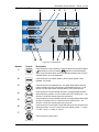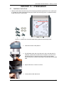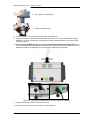
1
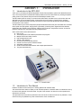
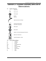
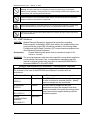
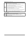
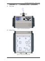
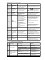
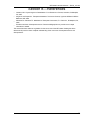
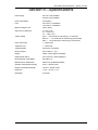
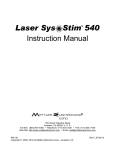
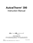
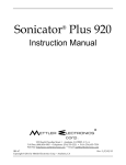
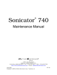
MTD 4000 Mettler Traction Decompression Instruction Manual THIS MANUAL APPLIES TO SOFTWARE VERSION 2.0 OR GREATER Distributed by: ® 1333 South Claudina Street Anaheim, CA 92805, U. S. A. Toll free: (800) 854–9305 • Telephone: (714) 533–2221 • FAX: (714) 635–7539 Web Site: http://www.mettlerelectronics.com • Email: [email protected] IR9–61 Copyright © 2010, 2014 by Mettler Electronics Corp.—Anaheim, CA Rev.M_11/19/14 Mettler Electronics Corp. — Rev.M_11/19/14 2 MTD 4000 Instruction Manual — Rev.M_11/19/14 Table of Contents Section Title 1 1.1 1.2 1.3 1.4 1.5 1.6 1.7 Introduction Introduction to the MTD 4000 Introduction to This Manual Safety Precautions Caution Shipping Damage Package Contents Limited Warranty 5 5 5 6 6 6 6 6 2.1 2.2 Symbol Glossary and List of Abbreviations Symbol Glossary List of Abbreviations 9 9 9 3.1 3.2 3.3 3.4 3.5 Indications, Safety Concerns, Contraindications and Precautions Indications Safety Concerns EMC Guidelines Contraindications Precautions 11 11 11 12 16 16 4.1 4.2 4.3 4.4 4.5 Controls and Functions Front View Bottom View Side View Rear View Control Panel 17 17 17 18 18 19 5.1 5.2 5.3 5.3.1 Installation Installation Instructions Installation Notes Changing the Factory Settings Changing the Force Units (F-0) 21 21 22 24 24 6.1 6.2 6.3 6.4 6.5 6.6 6.7 Operating Instructions General Operating Instructions Setting Up the Continuous Mode Setting Up the Intermittent Mode Changing Parameters During Treatment in the Continuous Mode Changing Parameters During Treatment in the Intermittent Mode Saving a Treatment Setup Recalling a Saved Treatment Setup 25 25 25 26 26 27 28 28 7.1 7.2 7.3 7.4 Maintenance and Troubleshooting Cleaning the MTD 4000 Routine Maintenance Error Codes Troubleshooting the MTD 4000 29 29 29 29 30 8 References 33 9 Specifications 35 10 10.1 10.2 Accessories Ordering Information MTD 4000 Accessories 37 37 37 2 3 4 5 6 7 Page 3 Mettler Electronics Corp. — Rev.M_11/19/14 Illustrations No. Title 1.1 The MTD 4000 4.1 Front View of the MTD 4000 17 4.2 Bottom View of the MTD 4000 17 4.3 Side View of the MTD 4000 18 4.4 Rear View of the MTD 4000 18 4.5 Control Panel 19 5.1 Bottom View of the MTD 4000 Showing Placement of Mounting Holes 21 5.2 Rear View of the MTD 4000 Showing Connectors and Switches 22 5.3 F-0 Controls and Displays 24 6.1 Continuous Mode Display 25 6.2 Intermittent Mode Display 26 6.3 Saving a Treatment Setup 28 4 Page 5 MTD 4000 Instruction Manual — Rev.M_11/19/14 Section 1: 1.1 Introduction Introduction to the MTD 4000 Thank you for purchasing the MTD 4000 (Mettler Traction Decompression) system from Mettler Electronics Corp. The microprocessor controlled MTD 4000 provides cervical or lumbar traction by exerting therapeutic pulling forces on the patient's body with enhanced reliability and ease of use. The MTD 4000 system is an easy to use device that offers static, intermittent, and cyclic traction with user definable hold, rest, and treatment times. It gently pulls the cervical spine or lumbar spine in opposite directions to draw the soft tissue around the cervical or lumbar joints and separate the distance between bone sections of the vertebra. The MTD 4000 may be used to help relieve peripheral radiation/sciatica and pain associated with: herniated discs, spinal root impingement, bulging discs, hypomobility, protruding discs, degenerative disc disease, degenerative disc disease, facet syndrome, posterior facet syndrome, compression fractures, acute facet problems, radicular pain, discogenic pain and prolapsed discs. Some of the features of the MTD 4000 are: Easy to use Active displays show all treatment parameters and progress. Multiple sensors and safety controls High strength traction rope Smooth, quiet operation Fits almost any existing table platform Clinician can save up to ten treatment setups Adjustable Hold/Rest times Continuous and Intermittent traction with multiple speed selection Two year limited warranty Figure 1.1—The MTD 4000 1.2 Introduction to This Manual Read the contents of this manual prior to treating patients with the MTD 4000. This manual has been written to assist you with the safe operation of the MTD 4000. It is intended for use by the owners and operators of the MTD 4000. The goal of this manual is to direct the correct operation and maintenance of this unit. The specifications and instructions presented in this manual are in effect at the time of its publication. These instructions may be updated at any time at the discretion of the manufacturer. 5 Mettler Electronics Corp. — Rev.M_11/19/14 1.3 Safety Precautions The MTD 4000 operates with high voltages. Servicing of the MTD 4000 should be performed by qualified biomedical technicians with training in traction service or it should be returned directly to the factory. To maximize safety during use, the unit should be plugged into a grounded wall outlet of proper voltage. Service may be obtained from the manufacturer by sending the MTD 4000 in its original shipping container to: Mettler Electronics Corp., 1333 South Claudina Street, Anaheim, CA 92805, ATTN: Service Department. (Telephone toll free: (800) 854–9305) This service may also be performed by qualified biomedical engineers or technicians trained in traction calibration. NOTE: All warranty repairs must be performed by Mettler Electronics Corp. or by a service facility authorized by Mettler Electronics to perform warranty repair work. 1.4 Caution Federal law restricts the sale of this device to, or on the order of a physician, dentist, veterinarian or any other practitioner licensed by law of the state in which he practices. Use of controls or adjustments or performance of procedures other than those specified herein may result in hazardous exposure to traction forces. Treatment should be administered only under the direct supervision of a health care professional. 1.5 Shipping Damage Your new MTD 4000 is shipped complete in one carton. Upon receipt, please inspect the carton and the unit for visible and hidden damage. If any damage is discovered, hold all shipping materials, including the carton, and call the shipping agent who delivered the unit. The carton in which your new MTD 4000 was received is specially designed to protect the unit during shipping. Please retain all shipping materials in the event that you will need to return your unit for servicing. NOTE: All repairs must be performed by Mettler Electronics Corp. or by a service facility authorized by Mettler Electronics to perform repair work. 1.6 Package Contents Your new MTD 4000 comes complete with all the necessary components to perform traction therapy. Below is a list of items that are included in the shipping carton. 1. MTD 4000 2. New style patient safety switch (ME 40005) 3. Traction rope with hook (ME 40002) 4. Detachable, hospital grade line cord, (ME 40003) 5. Three long and one short mounting screws and four split washers 6. Instruction Manual 1.7 Limited Warranty The MTD 4000 generating unit is warranted against defects in materials and workmanship for a period of two years from date of purchase. During the applicable warranty period Mettler Electronics Corp. will, at its discretion, either repair or replace the Product without charge for these types of defects. For service under this warranty, the Product must be returned by the buyer within the applicable warranty period to Mettler Electronics Corp. Shipping charges to and from Mettler Electronics Corp. under this warranty must be paid by the buyer. The buyer must also include a copy of the sales receipt or other proof of the date of purchase. If the Product is returned without proof of the date of purchase, it will be serviced as an out–of–warranty product at Mettler Electronics Corp.’s prevailing service rates. Alteration, misuse, or neglect of the Product voids this warranty. Except as specifically set forth above, Mettler Electronics Corp. makes no warranties, express or implied, including without limitation any implied warranty of merchantability or fitness for a particular purpose, with respect to the Product. If any implied warranties apply as a matter of law, they are limited in duration to one year. Mettler Electronics Corp. shall not be liable for any indirect, special, consequential or incidental damages resulting from any defect in or use of the Product. Any legal action brought by the buyer relating to this warranty must be commenced within one year from the date any claim arises and must be brought only in the state or federal courts located in Orange County, California. 6 MTD 4000 Instruction Manual — Rev.M_11/19/14 Some states do not allow limitations on how long an implied warranty lasts, or the exclusion or limitation of incidental or consequential damages, so the above limitations or exclusions may not apply to the buyer. This warranty gives the buyer specific legal rights, and the buyer may also have other rights which vary from state to state. 7 Mettler Electronics Corp. — Rev.M_11/19/14 8 MTD 4000 Instruction Manual — Rev.M_11/19/14 Section 2—Symbol Glossary and List of Abbreviations 2.1 Symbol Glossary I Power On. O Power Off. Time symbol Minutes Seconds Adjust time and force settings Continuous mode symbol Intermittent mode symbol Start symbol Stop symbol Attention, consult Accompanying Documents Refer to the instructions Type BF Equipment—Class I 2.2 A Kg Lb LED Min RH Sec Ser No. V W List of Abbreviations — — — — — — — — — — Amperes kilograms pounds Light Emitting Diode Minutes Relative Humidity Seconds Serial Number Volts Watts 9 Mettler Electronics Corp. — Rev.M_11/19/14 10 MTD 4000 Instruction Manual — Rev.M_11/19/14 Section 3 — Indications, Safety Concerns, Contraindications and Precautions 3.1 Indications The MTD 4000 traction device provides traction and mobilization of skeletal structures and skeletal muscles. The MTD 4000 may be used to relieve peripheral radiation/sciatica and pain associated with: Protruding discs Bulging discs Herniated discs Degenerative disc disease Posterior facet syndrome Acute facet problems Radicular pain Prolapsed discs Spinal root impingement Hypomobility Degenerative joint disease Facet syndrome Compressions fractures Joint pain Discogenic pain The MTD 4000 achieves these effects through decompression of intervertebral discs, that is, unloading due to distraction and positioning. 3.2 Safety Concerns Be cautious of the following when setting up or using the MTD 4000: Read this operation manual carefully before treatment. Please contact Mettler Electronics Corp. if this operation manual is incomplete. If the MTD 4000 functions or operates abnormally, please contact Mettler Electronics Corp. or your distributor for service. Clinicians should instruct their patients to power off device by pressing the patient safety switch, if they experience any discomfort. The MTD 4000 may be susceptible to interference originating from shortwave or microwave diathermy devices operating in close proximity to it. Avoid operating the MTD 4000 adjacent to and simultaneously with operating shortwave or microwave devices. When a traction session is completed, clean the harness, table and chair, which came in direct contact with patient’s skin according to the manufacturer’s cleaning instructions. Avoid use of the MTD 4000 in unclean environments. When the MTD 4000 is in use, make certain to maintain good ventilation around the unit to avoid heat buildup. Avoid use of this device on soft or uneven surfaces since that may potentially block the ventilation holes. When you are not using this device, place it in the Standby mode to save power. Avoid spilling liquids into the unit. This may damage the device or harm the patient. Avoid using this device in conjunction with other equipment on the same patient. Power off and remove power cord before cleaning the MTD 4000. 11 Mettler Electronics Corp. — Rev.M_11/19/14 Do not store in direct sunlight. Warning: The MTD 4000 may be susceptible to interference originating from shortwave diathermy units operating in close proximity to it. Avoid operating the MTD 4000 adjacent to and simultaneously with operating shortwave devices. Please use device in a dry environment. Water, steam, and other liquids will have significant deleterious effects on the electronic components. When using an extension cord with this device, do not use the same extension cord with other devices simultaneously to prevent surges, shorts, and possible electrically-caused fires. Please do not open the MTD 4000. Mettler Electronics reserves the right to repair and service only unopened devices. 3.3 EMC Guidance Medical Electrical Equipment needs special precautions regarding Electromagnetic Compatibility (EMC) and needs to be installed and put into service according to the EMC information provided in the following tables. Portable and mobile Radio Frequency (RF) communications equipment can affect Medical Electrical Equipment. Accessories: Hospital Medical grade power cord of a maximum length of 120 inches or 3 meters WARNING: The use of accessories, other than those specified, except those supplied or sold by Mettler Electronics Corp., Incorporated as replacement parts for internal or external components, may result in increased EMISSIONS or decreased IMMUNITY of the MTD 4000. CAUTION: Guidance and manufacturer’s declaration – electromagnetic emissions The MTD 4000 is intended for use in the electromagnetic environment specified below. The customer or the user of the MTD 4000 should assure it is used in such an environment. Emissions Test Compliance Electromagnetic environment-guidance RF emissions CISPR 11 Group 1 The MTD 4000 must emit electromagnetic energy in order to perform its intended function. Nearby electronic equipment may be effected. RF emissions CISPR 11 Class B Harmonic emissions IEC 61000-3-2 Applicable The MTD 4000 is suitable for use in all establishments other than domestic and those directly connected to the public low-voltage power supply network that supplies buildings used for domestic purposes. Voltage fluctuations/flicker emissions IEC 61000-3-3 Applicable 12 MTD 4000 Instruction Manual — Rev.M_11/19/14 Guidance and manufacturer’s declaration – electromagnetic immunity The MTD 4000 is intended for use in the electromagnetic environment specified below. The customer or the user of the MTD 4000 should assure that it is used in such an environment. Immunity test IEC 60601 test level Compliance level Electromagnetic environment –guidance Electrostatic discharge (ESD) IEC 61000-4-2 ±6 kV contact ±8 kV air ±6 kV contact ±8 kV air Floors should be wood, concrete or ceramic tile. If floors are covered with synthetic material, relative humidity should be at least 30%. Electrical fast transient/burst IEC 61000-4-4 ±2 kV for power supply lines ±1 kV for input/output lines ±2 kV for power supply lines ±1 kV for input/output lines Mains power quality should be that of a typical commercial or hospital environment. Surge IEC 61000-4-5 ±1 kV differential mode ±2 kV common mode ±1 kV differential mode ±2 kV common mode Mains power quality should be that of a typical commercial or hospital environment. Voltage dips, short interruptions and voltage variations on power supply input lines IEC 61000-411 <5% UT (>95% dip in UT) for 0.5 cycle 40% UT (60% dip in UT) for 5 cycles 70% UT (30% dip in UT) for 25 cycles <5% UT (>95% dip in UT) for 5 seconds <5% UT (>95% dip in UT) for 0.5 cycle 40% UT (60% dip in UT) for 5 cycles 70% UT (30% dip in UT) for 25 cycles <5% UT (>95% dip in UT) for 5 seconds Mains power quality should be that of a typical commercial or hospital environment. If the user of the MTD 4000 requires continued operation during power mains interruptions, it is needed that the MTD 4000 be powered from an uninterruptible power supply. Power frequency (50/60 Hz) magnetic field IEC 61000-4-8 3 A/m 3 A/m Power frequency magnetic fields should be at levels characteristic of a typical location in a typical commercial or hospital environment. NOTE UT is the A.C. mains voltage prior to application of the test level. 13 Mettler Electronics Corp. — Rev.M_11/19/14 Guidance and manufacturer’s declaration – electromagnetic immunity The MTD 4000 is intended for use in the electromagnetic environment specified below. The customer or the user of the MTD 4000 should assure that it is used in such an environment. Immunity test Conducted RF IEC 61000-4-6 Radiated RF IEC 61000-4-3 IEC 60601 test level 3 Vrms 150 kHz to 80 GHz 3 V/m 80 MHz to 2.5 GHz Compliance level 3V 3 V/m Electromagnetic environment guidance Portable and mobile RF communications equipment should be used no closer to any part of the MTD 4000, including cables, than the recommended separation distance calculated from the equation applicable to the frequency of the transmitter. Recommended separation distance d = 1.2√P d = 1.2√P 80MHz to 800 MHz d = 2.3√P 800MHz to 2.5 GHz where P is the maximum output power rating of the transmitter in watts (W) according to the transmitter manufacturer and d is the recommended separation distance in meters (m). Field strengths from fixed RF transmitters, as determined by an electromagnetic site survey, a should be less than the compliance level in each frequency range.b Interference may occur in the vicinity of equipment marked with the following symbol: NOTE 1 At 80 MHz and 800 MHz, the higher frequency range applies. NOTE 2 These guidelines may not apply in all situations. Electromagnetic propagation is affected by absorption and reflection from structures, objects and people. a Field strengths from fixed transmitters, such as base stations for radio (cellular/cordless) telephones and land mobile radios, amateur radio, AM and FM radio broadcast and TV broadcast cannot be predicted theoretically with accuracy. To assess the electromagnetic environment due to fixed RF transmitters, an electromagnetic site survey should be considered. If the measured field strength in the location in which the MTD 4000 is used exceeds the applicable RF compliance level above, the MTD 4000 should be observed to verify normal operation. If abnormal performance is observed, additional measures may be necessary, such as reorienting or relocating the MTD 4000. b Over the frequency range 150 kHz to 80 MHz, field strengths should be less than 3 V/m. 14 MTD 4000 Instruction Manual — Rev.M_11/19/14 Recommended separation distances between portable and mobile RF communications equipment and the MTD 4000 The MTD 4000 is intended for use in an electromagnetic environment in which radiated RF disturbances are controlled. The customer or the user of the MTD 4000 can help prevent electromagnetic interference by maintaining a minimum distance between portable and mobile RF communications equipment (transmitters) and the MTD 4000 as recommended below, according to the maximum output power of the communications equipment. Rated maximum output power of transmitter W Separation distance according to frequency of transmitter m 150 kHz to 80 MHz d = 1.2√P 80 MHz to 800 MHz d = 1.2√P 800 MHz to 2.5 GHz d = 2.3√P 0.01 0.12 0.12 0.23 0.1 0.38 0.38 0.73 1 1.2 1.2 2.3 10 3.8 3.8 7.3 100 12 12 23 For transmitters rated at a maximum output power not listed above, the recommended separation distance d in meters (m) can be estimated using the equation applicable to the frequency of the transmitter, where P is the maximum output power rating of the transmitter in watts (W) according to the transmitter manufacturer. NOTE 1 At 80 MHz and 800 MHz, the separation distance for the higher frequency range applies. NOTE 2 These guidelines may not apply in all situations. Electromagnetic propagation is affected by absorption and reflection from structures, objects and people. Guidance and manufacturer’s declaration No. Mode Of Operation Essential Performance Degradation Allowed 1 Unit tested to 230 VAC for CE Unit tested to 120 VAC for US/Canada Unit designed to be failure safe in abnormal condition 2 Unit provides automatic traction. Reset allowed as long as failure safe 15 Mettler Electronics Corp. — Rev.M_11/19/14 3.4 Contraindications Do not use traction on patients with structural disease due to tumors or infection (e.g., osteomyelitis, spinal caries, and ankylosingspondylitis). Do not use on patients with joint instability, hypermobility or spinal fracture. Do not use on patients who have rods or screws in the spine (fusion with internal fixation). Do not use traction on patients with osteoporosis. Traction should not be administered to individuals who are or may be pregnant. Do not use on patients with severe cardiovascular disease, vascular compromise, aortic aneurysm or severe respiratory disease. Do not use traction on patients where movement is contraindicated. Do not use on patients with acute sprains, strains or inflammation that could be aggravated by traction. Stop traction if there is an increase in radiated pain to the extremities (radicular pain). Do not use lumbar traction on patients with hiatal or abdominal hernias. 3.5 Precautions Use caution on using traction on patients with claustrophobia. Take precautions when using cervical traction on patients with TMJ or dentures. Use care on patients who do not tolerate prone or supine positions, they may not be good candidates for traction therapy. 16 MTD 4000 Instruction Manual — Rev.M_11/19/14 Section 4— Controls and Functions 4.1 Front View Figure 4.1—Front view of the MTD 4000 4.2 Bottom View Figure 4.2—Bottom view of the MTD 4000 17 Mettler Electronics Corp. — Rev.M_11/19/14 4.3 Side View Figure 4.3—Side view of the MTD 4000 4.4 Rear View Figure 4.4—Rear view of the MTD 4000 18 MTD 4000 Instruction Manual — Rev.M_11/19/14 4.5 Control Panel 3 12 4 11 9 5 6 1 7 2 10 8 13 Figure 4.5—Control Panel Number 1 2 Control Description Press this button to switch between Continuous Mode and Intermittent Mode. ( stands for Continuous Mode; stands for Intermittent Mode.) When using Continuous Mode, some non-applicable settings such as HOLD and REST times, will not be illuminated. Press this button to set traction speed. There are three speeds – FAST, NORMAL, and SLOW. 3 Press this button to set treatment time. The digital display flashes after the button is pressed. Turn the control knob to set treatment time from 1 to 99 minutes. The left LED indicator will keep flashing during treatment time. 4 Press this button to set pull strength hold time. The digital display will flash after the button is pressed. Turn the control knob to set hold time from 1 - 99 seconds. The left LED indicator lights during hold time. 5 Press this button to set pull strength rest time. The digital display flashes after the button is pressed. Turn the control knob to set rest time from 1 - 99 seconds. The left LED indicator lights during rest time. 6 Press this button to set strength. Hold & Rest setting can be exchanged upon pressing the button. Turn the control knob to set strength (HOLD:2 - 90 kg / 4 - 198 lb;REST:0 - 89kg / 0 - 195 lb). 7 Press this button to stop traction. 19 Mettler Electronics Corp. — Rev.M_11/19/14 8 Press this button to start traction. Press again the output force will be released. 9 Control knob — To increase or decrease the value of a setting. (Clockwise→ Increase; Anti-clockwise→ Decrease.) 20 10 The column shows the actual output value during the treatment. 11 When the device starts to increase the pulling strength, the PULL indicator lights. 12 When the device starts to decrease the pulling strength, the RELEASE indicator lights. 13 Lb / Kg indicator: The force units being used on the device. MTD 4000 Instruction Manual — Rev.M_11/19/14 Section 5—Installation 5.1 Installation Instructions 1. Attach the MTD 4000 to the table using the accompanying hardware supplied with the unit. (See Figure 5.1) Please note, lower right hand mounting hole requires short mounting screw. An example with step by step instructions is shown below: Figure 5.1— Bottom View of the MTD 4000 Showing Placement of Mounting Holes 2. Center MTD 4000 on table platform. 3. The MTD4000 comes with 3 long bolts (3/4") and 1 short bolt (3/8") for installation. Please follow the instruction to install the “short bolt” on the hole with RED arrow. Using the long bolt on this hole may damage internal components. Position bolts using the bolts provided with the MTD 4000. 4. Tighten bolts with ½ in wrench or socket. 5. Loosen platform slide retainer bolt. 21 Mettler Electronics Corp. — Rev.M_11/19/14 6. Push platform to opposite side. 7. Position and tighten bolts. 8. Connect the line cord to the back of the MTD 4000. (See Figure 5.2) 9. Plug the line cord into a grounded wall outlet that is rated at AC 110V~120V, 50/60Hz (other voltages available). Your mains power supply must match the voltage requirements listed on the serial number label of your device. 10. Do not connect the MTD 4000 to a power supply rated differently than that described above. The unit comes equipped with a grounded line cord. This plug provides grounding for the MTD 4000. Do not defeat its purpose by using adapters or any other means of attaching to a wall outlet. Figure 5.2— Rear View of the MTD 4000 Showing Connectors and Switches 11. Plug the patient safety switch into the back of the unit. 12. Attach the desired harness for either lumbar or cervical traction. 22 MTD 4000 Instruction Manual — Rev.M_11/19/14 13. Pictured below are the accessories that come with the MTD 4000. MTD 4000 One Power Cord (40003) New Style Patient Safety Switch (40005) Four Mounting Screws and Four Split Washers 14. The accessories shown below are only for reference. Your distributor may supply other accessories for use with this device. Lumbar traction showing traction belt Lumbar traction showing traction belt and positioning accessories. Lumbar traction showing traction belt Cervical traction showing clevis and traction harness 23 Mettler Electronics Corp. — Rev.M_11/19/14 5.2 Installation Notes 1. Only pull the traction rope in the correct direction as shown below. 5.3 Changing the Factory Settings 1. Turn the MTD 4000 off. 2. Hold the “Set” button down while you turn on the power at the rear of the unit. 3. Continue to press and hold down the set button at least 3 seconds. The system will enter “Factory Setting Mode” and display “F–0” in the “Actual” display window as shown in Figure 5.3. 5.3.1 Changing the Force Units (F-0) Figure 5.3— F-0 Controls and Displays 1. Make sure the device is under Factory Setting Mode, showing an “F-?” in the “Actual” display window. 2. Turn the control knob until “F-0” is displayed in the “Actual” display window and press the start button to select the “F-0” code. Press the set button to switch to a different traction force unit “LB” or “KG”. The new setting will be automatically saved. 3. Press the “Stop” key to leave the factory setting mode and return to normal operation. 24 MTD 4000 Instruction Manual — Rev.M_11/19/14 Section 6—Operating Instructions 6.1 General Operating Instructions Before you start: a) b) c) d) e) f) Review precautions and contraindications in Section 3. Verify connection of the line cord to a grounded wall receptacle and the MTD 4000. Make sure the patient safety switch is attached and handed to the patient. Note: MTD 4000 will display E-4 if patient safety switch is not attached. Note: Descriptions of the symbols used on controls are in Section 2. Note: Detailed descriptions of controls and connections are in Section 4. 1. Turn the power on. 2. The automatic startup test will run for 1~2 seconds. 3. After test completion, the user can proceed with normal parameter setting. 6.2 Setting up the Continuous Mode Figure 6.1—Continuous Mode Display 1. Press the output mode button to set the MTD 4000 to the continuous mode. The LED next to should be lit. 2. Press the set button to set traction force. The “Hold” display will start flashing. Turn the control knob to set the desired value. Press the set button again to save the Hold value. NOTE: When an indicator is flashing, no key press within 10 seconds will cause the flashing to automatically stop. 3. Press the time button to set the treatment time. The timer display will start flashing. Turn the control knob to set the desired time in minutes. Press timer button again to save the time. Flashing stops once the time is saved. 4. Press the speed button to set traction speed (FAST/NORMAL/SLOW). 5. Press the start button. All parameter settings are confirmed and the treatment starts. 25 Mettler Electronics Corp. — Rev.M_11/19/14 6. Press the stop button to stop treatment and release the traction force. The system will revert to Normal Setting status. NOTE: The patient can press the “Patient Safety Button” to stop treatment and release the traction force if any discomfort is experienced during the treatment. The alarm buzzer will sound and the display will show an error code “E-4”. To revert to a safe status “E-4” can be removed by pressing the stop button. 6.3 Setting up the Intermittent Mode Figure 6.2—Intermittent Mode Display 1. Press the output mode button twice to set the MTD 4000 to the intermittent mode. The LED next to should be lit. 2. Press the set button to set traction force. The “Hold” display will start flashing. Turn the control knob to set the desired force value. Press the set button again to save the Hold force value. Then the “Rest” display will start flashing. Turn the control knob to set the desired rest force value. Press the set button again to save the rest force value. NOTE: When an indicator is flashing, no key press within 10 seconds will cause the flashing to automatically stop. 3. Press the time button to set the treatment time. The timer display will start flashing. Turn the control knob to set the desired time in minutes. Press timer button again to save the time. Flashing stops once the time is saved. 4. Press the hold button to set the hold time. The hold display will start flashing. Turn the control knob to set the desired hold time in seconds. Press hold button again to save the hold time. Flashing stops once the hold time is saved. 5. Press the rest button to set the rest time. The rest display will start flashing. Turn the control knob to set the desired rest time in seconds. Press timer button again to save the rest time. Flashing stops once the rest time is saved. 6. Press the speed button to set traction speed (FAST/NORMAL/SLOW). 26 MTD 4000 Instruction Manual — Rev.M_11/19/14 7. Press the start button. All parameter settings are confirmed and the treatment starts. 8. Press the stop button to stop treatment and release the traction force. The system will revert to Normal Setting status. 9. NOTE: The patient can press the “Patient Safety Button” to stop treatment and release the traction force if any discomfort is experienced during the treatment. The alarm buzzer will sound and the display will show an error code “E-4”. To revert to the operational status, “E-4” can be removed by pressing the stop button. 6.4 Changing Parameters during Treatment in the Continuous Mode 1. While a treatment is running, press the set button to adjust the traction force. The unit beeps and the “Hold” display will start flashing. Turn the control knob to set the desired force value. Press the set button again to save the hold force value and resume treatment. NOTE: When an indicator is flashing, no key press within 10 seconds will cause the flashing to automatically stop. 2. While a treatment is running, press the time button to adjust treatment time. The unit beeps and the timer display will start flashing. Turn the control knob to set the desired time. Press the time button again to save the time and resume treatment. 6.5 Changing Parameters during Treatment in the Intermittent Mode 1. While a treatment is running, press the set button to adjust traction force. The unit beeps and the “Hold” display will start flashing. Turn the control knob to set the desired force value. Press the set button again to save the hold force value and adjust the rest force value. After the rest force value is set, press the set button to resume treatment. 2. While a treatment is running, press the time button to adjust treatment time. The unit beeps and the timer display will start flashing. Turn the control knob to set the desired time. Press the time button again to save the time and resume treatment. 27 Mettler Electronics Corp. — Rev.M_11/19/14 6.6 Saving a Treatment Setup Figure 6.3—Saving a Treatment Setup 1. Set the desired treatment parameters using either section 6.2 for the continuous mode or section 6.3 for the intermittent mode. 2. Press and hold the stop button for 3 seconds. The “Actual” display window will show “SE0”. You have entered the memory function mode. 3. Press the set button to save the treatment setup to “SE0” memory and to exit the save function. 4. There are a total of 10 memory slots: “SE0” through “SE9”. As an example, to save a treatment setup in the “SE8” position, after step 2, turn the control knob until the actual display window shows “SE8”, then press the set button to save the treatment setup and to exit the save function. 6.7 Recalling a Saved Treatment Setup 1. Press and hold the stop button for 3 seconds. The “Actual” display window will show “SE0”. You have entered the memory function mode. 2. Turn the control knob until the actual display window shows whichever treatment setup you would like to use, “SE0” through “SE9”. 3. Once the code for the treatment setup you would like to use is displayed in the “Actual” display window, press the start button to select it. 4. The treatment is ready to go, so press the “Start” button to begin the treatment. 28 MTD 4000 Instruction Manual — Rev.M_11/19/14 Section 7—Maintenance and Troubleshooting 7.1 Cleaning the MTD 4000 1. The MTD 4000 can be wiped off with a damp cloth. The power cord should be disconnected from the unit before this is done. In the case of stubborn dirt a gentle household cleaner can be sprayed on the cloth and then wiped on the unit. If this method is used, remove any cleaner residue with a damp cloth. Do not spray cleaner onto the unit. 2. Do not use any cleaning agents containing high contents of phenol derivates, alcohol, compounds of chlorine or peracetic acid. It is recommended to use aldehyde-based disinfectants. The device is not suited for heat sterilization or for sterilization with gases. 3. Follow the manufacturer’s instructions for cleaning all harnesses and treatment table surfaces after use on each patient. 7.2 Routine Maintenance 1. To assure accurate performance of the MTD 4000, calibration should be performed on an annual basis by a qualified biomedical technician. 2. Standard medical electrical safety checks should be performed annually by qualified biomedical engineers or technicians trained to perform these procedures. 3. Inspect the traction rope for wear. It should be replaced if signs of wear are noticed. 4. The manual calibration indicated in the instruction manual should be performed routinely. 5. Annually, the auto-calibration should be performed by a qualified biomedical technician. 6. Replace the traction rope every two years. This service should be performed by a qualified biomedical technician. 7.3 Error Codes Error Code *E-1* Description Cause of Error Solution Calibration data error The saved calibration data is wrong; or the position of limit switch is not adjusted. *This error detection is for factory use only. If it happens during the operation, please contact Mettler Electronics for repair. The clutch module is worn or broken. Restart the system to remove the error. E-2 Clutch Starting error E-3 Clutch closing error The motor control board is broken. The clutch module is worn or broken. E-4 The patient safety switch has been pressed. The Patient Stop Switch is being pressed, disconnected, unplugged, or broken. E-5 Overload detection The pull force reached safety limit. Force meter Communication error The digital force meter is not connected to the traction unit during auto- *E-6* If the error still occurs, please contact Mettler Electronics for repair. Restart the system to remove the error. If the error still occurs, please contact Mettler Electronics for repair. Press the STOP button to remove the error code and check the cable connection. If the error still occurs, replace it with the new one. If the new emergency cable does not resolve the problem and error is still occurring, send back to Mettler Electronics for repair. Restart the system to remove the error. If the error still occurs, please contact Mettler Electronics for repair. *This error detection is for factory use only. If it happens during the operation, please contact Mettler Electronics for 29 Mettler Electronics Corp. — Rev.M_11/19/14 calibration. E-7 Force sensor error The force sensor is broken, or the rope is disconnected from the force sensor. Contact your local distributor for repair E-8 Sudden or abnormal pull strength The output force exceeds the safety force level. Press the STOP button to remove the error. If the error cannot be removed, please contact Mettler Electronics for repair. E-9 Treatment defaults memory error EEPROM (Electrically Erasable Programmable Read-Only Memory) reading error Turn off the system and turn it back on. If the problem still occurs, contact Mettler Electronics for repair. E-A *E-b* E-c 3 30 - strap too loose. - Patient’s body is not positioned appropriately on the table - Motor not performing correctly. Check the condition of traction rope. And, Turn on and try again. If damaged the rope is damaged or the E-A error persists, please contact Mettler Electronics for repair. *This error is for factory use only. If it happens during operation, send back to Mettler Electronics for repair. Auto-calibration error Force sensor displacement error Restart the system by turning it off and then on again. Check the straps (lumbar/chest/cervical) to make sure they are properly attached to the patient. The traction rope didn’t retract completely. The force sensor is broken. Turn off the system and turn it back on. Unhook the traction rope and let it retract completely into the system. If the error still occurs, please contact Mettler Electronics for repair. System memory error Contact Mettler Electronics for repair service. E-E Display error Turn off the system and turn it back on. If the problem still occurs, contact Mettler Electronics for repair service. Item 2 Motor performance error Pulling or releasing takes longer than the default time, 50 seconds. This will happen if the patient is incorrectly strapped where traction forces cannot reach the set value. E-d 7.4 1 repair. Troubleshooting the MTD 4000 Description Fail to power on. Cause of Error Solution Fuse is broken. Replace fuse. AC Power Cord is damaged. Replace power cord. Transformer or main control board is damaged. Contact Mettler Electronics for repair service. No traction output or abnormal traction output. Traction rope broken or mechanical parts broken. Contact Mettler Electronics for repair service. Firmware error or calibration error. Contact Mettler Electronics for repair service. On/off switch or push Program is still running or the traction Wait until the work is button out of function. 4 No display or abnormal display. force is releasing. MTD 4000 Instruction Manual — Rev.M_11/19/14 completed. Membrane or potentiometer is damaged. Contact Mettler Electronics for repair service. The main control board is damaged or has a bad connection. Contact Mettler Electronics for repair service. The main control board is damaged or has a bad connection. Contact Mettler Electronics for repair service. Display is damaged. Contact Mettler Electronics for repair service. NOTE: Please contact Mettler Electronics Corp. before taking any repair action. Please write down the software revision that appears in the “Actual Force” window during the power up procedure. Our service department may be reached at 800.854.9305 from 7 am until 3:30 pm Monday through Friday. You may also reach us via email at [email protected]. 31 Mettler Electronics Corp. — Rev.M_11/19/14 32 MTD 4000 Instruction Manual — Rev.M_11/19/14 Section 8—References * Cameron, MH. Physical Agents in Rehabilitation: From Research to Practice, Saunders, Philadelphia, PA, 2003. * Knight KL and Draper DO. Therapeutic Modalities: The Art and Science, Lippincott Williams & Wilkins. Baltimore, MD, 2008. * Michlovitz SL and Nolan TP. Modalities for Therapeutic Intervention, F.A. Davis Co., Philadelphia, PA, 2005. * Excellent overviews of therapeutic traction. Extensive bibliographies can provide more in-depth information if needed. This manual has been written as a guideline for the correct use of the MTD 4000. Reading the above references will provide a more complete understanding of the correct use of therapeutic traction and decompression. 33 Mettler Electronics Corp. — Rev.M_11/19/14 34 MTD 4000 Instruction Manual — Rev.M_11/19/14 Section 9—Specifications Power Supply AC 110V~120V, 50/60Hz AC 220V~240V, 50/60Hz Power Consumption 100 W (Max.) Fuse 2.0 A/ 250 V× 2 Slow Blow 1.0 A/ 250 V× 2 Slow Blow Maximum Output Force 198 lb / 90 Kg Output Force Tolerances 4 – 44 lb ± 2 lb 45 – 110 lb ± 3 lb 111 – 198 lb ± 4 lb Traction Speed Fast — ~5-6 Seconds to reach 90 kg. (<10 seconds) Normal — ~12-15 Seconds to reach 90 kg.(<20 seconds) Slow — ~22-25 Seconds to reach 90 kg.(<30 seconds) Hold / Rest Period 1 - 99 Seconds Treatment Time 1 - 99 minutes Treatment Mode Continuous / Intermittent Security System Error Codes E-1 - E-E Display Yellow / Green Digital LED Display Patient Safety Switch 2 Pin connector, newly redesigned Electromagnetic Compatibility IEC 60601-1-2 Medical Device Classification Class IIa as per MDD 93/42/EEC Operation Temperature/Humidity 0~40˚C / 90%RH under Storage Temperature/Humidity -20~60˚C / 90%RH under Dimension L 14.2" × W 12.2" × T 9" Net Weight 32 pounds 35 Mettler Electronics Corp. — Rev.M_11/19/14 36 MTD 4000 Instruction Manual — Rev.M_11/19/14 Section 10—Accessories 10.1 Ordering Information: Therapy products and accessories are available from Mettler Electronics authorized Distributors. For information regarding either Mettler products or a distributor near you, please call toll free, (800) 854–9305 or phone (714) 533–2221 in areas outside the continental United States. Ask for Customer Service. Mettler Electronics is open from 7 AM until 5 PM Pacific Time for your convenience. You may also reach Customer Service via email at [email protected]. 10.2 MTD 4000 Accessories Catalogue # Item Description 40002 40003 40004 40005 Traction rope with hook Power cord for the MTD 4000, 110 V (domestic) Power cord for the MTD 4000, 220 V (international) New style patient safety switch 37 Mettler Electronics Corp. — Rev.M_11/19/14 38